1
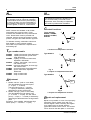
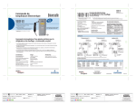
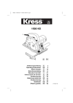
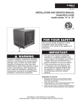
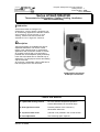
European Refrigeration Controls Catalogue Catalog Section 1 Product Bulletin A19A Issue 03/03/2003 PSC9705 Series A19A/A19B/A19D Thermostats for Refrigeration, Cooling, Heating, Ventilation and Air-conditioning Introduction These thermostats are designed for refrigeration, cooling, heating, ventilation and air-conditioning applications. Standard models are provided for remote sensing or room sensing. Models with manual reset are available for low or high limit functions. Description These thermostats are available with fixed or adjustable differential. The various control ranges cover a broad range of temperature applications with a minimum number of models. On request a built-in high or low limit stop is possible and can be adjusted quickly and easily in the field. All models have a universal way of adjustment. For this purpose a knob and sealing cap are enclosed. All A19 style 1 wholesaler code models have a bulb clamp plus screw also enclosed. A19A capillary thermostat A19B space thermostat Feature and Benefits Liquid filled sensing element No cross ambient temperature problems Contact differential over the whole range Dust tight Penn switch Prevents pollution of the contacts by electrostatic influences. Trip free manual reset Override is not possible in the control function Front adjustment Less mounting space required. © 2003 Johnson Controls Inc. Order No. PD-A19A-E Catalogue Section 1 A19A Issue 03/03/2003 2 Note Note These controls are designed for use only as operating controls. Where an operating control failure would result in personal injury or loss of property it is the responsibility of the installer to add devices or systems that protect against, or warn of, control failure. SPDT contacts are standard on all models. Instruments have compact sizes. Types A19ACC and A19ADC have a trip-free manual reset . Reset button must be pressed and released. Contact cannot be blocked in closed position. All types have VDE and SEV approval. To facilitate ordering, wholesaler codes have been added on some universal models. All models are provided with a separate knob and sealing cap. Type number matrix A19AAC A19AAF A19ABC A19ACC A19ADC A19BAC A19BBC A19DAC A19DAF capillary thermostat, fixed differential. capillary thermostat, special close fixed differential. capillary or immersion thermostat, adjustable differential. capillary thermostat, lock-out low with manual reset. immersion thermostat, lock-out high with manual reset. space thermostat, fixed differential. space thermostat, adjustable differential. strap-on thermostat. strap-on thermostat The standard screwdriver adjustment can be converted easily in the field to knob adjustment. Also concealing of adjustment and scale is possible after installation. Contact functions Types A19AAC, A19AAF, A19ABC, A19BAC, A19BBC, A19DAC 3 2 θ> 1 Fig. 1 1-2 closes on temperature increase Type A19ACC 2 3 θ< 1 Fig. 2 1-2 opens on temperature decrease Type A19ADC 2 3 Adjustment 1. Models “set low” (refer to cover label) The dial indicates the low switch point (1 - 2 open, 1 - 3 closed). The high switch point (1 - 2 closed, 1 - 3 open) is obtained by adding the differential to the low switch point. 2. Models “set high” (refer to cover label) The dial indicates the high switch point (1 - 2 closed, 1 - 3 open). The low switch point (1 - 2 open, 1 - 3 closed) is obtained by deducting the differential from the high switch point. Exception: Type A19ADC, dial indicates high switch point ( 1 - 3 closed, 1 - 2 open). Catalogue Section 1 θ> 1 Fig.3 1-2 opens on temperature increase Repair and replacement Repair is not possible. In case of an improperly functioning control, please check with your nearest supplier. When contacting the supplier for a replacement you should state the type/model number of the control. This number can be found on the data plate or cover label. © 2003 Johnson Controls Inc. Order No. PD-A19A-E A19A Issue 03/03/2003 3 Sensor styles ½" x 14 NPT 60 58.3 Fig. 7 Style 2 Fig. 4 Style 1a (drawn bulb) Fig.5 Style 1b swaged bulb, can be used with closed-tank connector FTG13A-600 Fig. 8 Style 20 ½ " x 14 NPT 33.3 60 Fig. 6 Style 4h Fig. 9 Style 3 (coil) Bulb size and finish, bulb wells Range (°C) Style 1b 3 1b 3 Bulb size (mm) 9.5 x 110 9.5 x 135 - -35 to +10 -35 to +10 -5 to +28 -5 to +28 Tin-plated Stainless Steel Tin-plated Stainless Steel WEL14A602R WEL14A603R - -35 to +40 -35 to +40 0 to 13 0 to 43 1 to 60 5 to 32 10 to 95 40 to 120 35 to 150 1b 3 1a 3 1b 1b 1a 1b 1a 9.5 x 110 9.3 x 80 9.5 x 115 9.5 x 155 7.4 x 75 9.5 x 100 5 x 265 Tin-plated Stainless Steel Stainless Steel Tin-plated - 90 to 290 1a 5 WEL14A602R WEL16A601R WEL14A602R No bulb well available WEL11A601R WEL14A602R No bulb well or closed tank connector possible No bulb well or closed tank connector possible © 2003 Johnson Controls Inc. Order No. PD-A19A-E x 155 Finish - Bulb well (optional) Catalogue Section 1 A19A Issue 03/03/2003 4 Type number selection table: Range ( °C) Diff. (K) Bulb style Setting (see page 2 adjustment) Cap. length Max. bulb temp. Wholesaler code Order number Type A19AAC Capillary thermostat, fixed differential -35 to +10 -5 to +28 -5 to +28 1 to 60 40 to 120 35 to 150 90 to 290 2.5 2 2 2 3.5 4 5.5 1b 1b 1b 1b 1b 1a 1a set set set set set set set low low low low high high high 2m 2m 5m 3m 2m 2m 2m 60 °C 60 °C 60 °C 85 °C 145 °C 180 °C 290 °C A19AAC-9102 A19AAC-9005 A19AAC-9124 A19AAC-9127 A19AAC-9009 A19AAC-9107 A19AAC-9108 Type A19ABC Capillary or immersion thermostat, adjustable differential -35 to +40 -35 to +40 -35 to +10 -5 to +28 1 to 60 1 to 60 10 to 95 40 to 120 2.8 to 8 2.8 to 8 2.8 to 11 2 to 8 2 to 8 2 to 8 3.5 to 13 3.5 to 13 1b 1b 1b 1b 1b 1b 1a 2 set set set set set set set set low low low low low low high high 40 to 120 3.5 to 13 4h set high 3.5 m 6.5 m 2m 2m 5m 3m 3.5 m - 60 °C 60 °C 60 °C 60 °C 85 °C 85 °C 115 °C 145 °C 2m 145 °C A19-A4 A19-A5 A19-A1 A19-A2 A19ABC-9037 A19ABC-9036 A19ABC-9103 A19ABC-9104 A19ABC-9117 A19ABC-9116 A19ABC-9106 A19ABC-9011 bulb well incl. A19ABC-9012 bulb well incl. A19-A3 Type A19ACC Capillary thermostat, lock-out low with manual reset -35 to +10 -35 to +10 N -35 to +10 N -35 to +10 N -5 to +28 -5 to +28 -5 to +28 6 M 6 M 6 M 6 M 4 M 4 M 4 M 1b 1b 1b 1b 1b 1b 1b set set set set set set set low low low low low low low 2m 3.5 m 5m 6.5 m 2m 5m 3m 60 °C 60 °C 60 °C 60 °C 60 °C 60 °C 60 °C A19ACC-9100 A19ACC-9105 A19ACC-9111 A19ACC-9116 A19ACC-9101 A19ACC-9103 A19ACC-9107 A19-F Type A19ADC immersion thermostat, lock-out high with manual reset 40 to 120 7O 2 set high - 145 °C A19ADC-9200 bulb well incl. Type A19AAF Capillary thermostat, close, fixed differential 0 to 10 0 to 10 5 to 32 1.5 1.5 0.75 1a 1a 1b set low set low set high 2m 2m 2m 80 °C 80 °C 60 °C A19AAF-9101 A19AAF-9102 A19AAF-9103 A19-M P M Indicates temperature increase above cut-out point to make reset possible. O Indicates temperature decrease below cutout point to make reset possible. N Low limit stop factory set +2.5 °C may be removed in the field. P Milk-cooler thermostat. Catalogue Section 1 © 2003 Johnson Controls Inc. Order No. PD-A19A-E A19A Issue 03/03/2003 5 Type number selection table: Range ( °C) Diff. (K) Bulb style Setting Cap. length (see page 2 adjustment) Max. bulb temp. Wholesaler code Order number Type A19BAC Space thermostat, fixed differential -35 to +10 -5 to +28 0 to 43 2.5 2 3 3 set low set low - 60 °C 60 °C A19-B1 A19-B2 A19BAC-9250 A19BAC-9251 2 3 set high - 60 °C A19-B3 A19BAC-9001 Type A19BBC Space thermostat, adjustable differential -35 to +40 2.8/8 3 set low - 60 °C A19-B4 A19BBC-9275 Type A19DAC, Strap-on thermostat, fixed differential 40 to 120 92 to 116 4.5 2 20 20 set high set high - 145°C 145°C A19DAC-9001 A19DAF-9001 Note: If what you need is not in the type number selection table, then please contact your representative. © 2003 Johnson Controls Inc. Order No. PD-A19A-E Catalogue Section 1 A19A Issue 9811 6 Accessories (optional) 1 2 3 C A B Order no. Dimension A Dimension B Dimension C Internal WEL11A601R 60 mm 118 mm 7.3 mm WEL14A602R 125 mm 171 mm 9.8 mm WEL14A603R 147 mm 193 mm 9.8 mm WEL16A601R 71 mm 117 mm 9.5 mm 1. Bushing 2. Set screw 3. Adapter, 1/2"-14 NPT Fig. 10 Bulb well (brass, copper pipe) 76 63 27 11.5 1/2"-14 NPT ø 5.5 (3x) Fig. 11 Duct flange to be used with closed-tank connector FTG13A-600R. Order number T-752-1001 Catalogue Section 1 1 2 3 1. 2. 3. 4. 5. 6. 4 3 5 6 Style 1b bulb support tube Packing nut Washer Packing Adapter, 1/2"-14 NPT Bulb Fig. 12 Closed-tank connector Order number FTG13A-600R © 2003 Johnson Controls Inc. Order No. PD-A19A-E A19A Issue 03/03/2003 7 Dimensions (mm) 21.5 13 1 2 19 28 19 32 55 40 3.6 7 13 125 75 16 6 3 1 2 3 4 4 46.5 Reset lever Knob packed separately with the control 22.3 mm dia. cable inlet hole for PG-16 Earth screw Fig. 13 © 2003 Johnson Controls Inc. Order No. PD-A19A-E Catalogue Section 1 A19A Issue 9811 8 Specifications CE Conformity Operating range Differential Differential adjustments Sensor styles Electrical ratings Ambient temp. limits Conduit opening Material Protection Class Shipping weight Dimensions According to low voltage directive and EMC directive -35 to +290 °C. See type number selection table. See type number selection table. Controls with adjustable differential (types A19ABC and A19BBC) have an adjustment lever under the cover. Styles 1a, 1b, 2, 3, 4h, and 20 (see drawings page 3) ~15(8) A, 230 V; except A19AAF and A19DAF: ~15(3) A 230 V, and A19ABC-9036/9037: ~15(5) A 230 V -35 to +55 °C 22.3 mm diam. hole for PG-16 connector Case 1.75 mm cold-rolled zinc plated steel Cover 1.5 mm ABS plastic IP30 Individual pack 0.4 kg Overpack 10 kg (24 pcs) (see dimension drawing) The performance specifications are nominal and conform to acceptable industry standards. For applications at conditions beyond these specifications, consult the local Johnson Controls office or representative. Johnson Controls shall not be liable for damages resulting from misapplication or misuse of its products. Johnson Controls International, Inc. Headquarters: European Headquarters: European Factories: Branch Offices: Milwaukee, WI, USA Westendhof 8, 45143 Essen, Germany Lomagna (Italy), Leeuwarden (The Netherlands) and Essen (Germany) Principal European Cities. This docum ent is subject to change Catalogue Section 1 Printed in Europe © 2003 Johnson Controls Inc. Order No. PD-A19A-E PSC9720 SHT067N600(003) Adjustment Instelling Ajuste Justering Seřízení Réglage Ajuste Justering Justering Einstellung Regolazione Säätö Pύθµιση ENGLISH ! Instruction sheet 1 2 3 4 5 A19 Specification Specificatie Especificação Beskrivelse Technická data Description Especificación Specifikationer Spesifikasjoner Spezifikation Specifiche Erittely Προδιαγραφέσ Setpoint dial Knob for adjustment (separate packed) Cap for concealed adjustment (separate packed) Differential lever (adjustable differential models only) Cover (not on models A19AGC, A19AGF and BGC models) These controls are designed for use only as operating controls. Where an operating control failure would result in personal injury or loss of property, it is the responsibility of the installer to add devices or systems that protect against, or warn of, control failure. Installation DO NOT TURN SEALED SCREWS 180° 2 1 2 3 4 °C SP 3 1 ! Disconnect from power supply before the cover is removed. ! For A19AGC, A19AGF and A19BGC Disconnect power supply before adjusting the control. Wiring All wiring should conform to local codes and must be carried out by authorized personnel only. When using multi stranded wire apply a cable ferrule to the cable end. 3 Set Low 1 3 2 5 1 Check out procedure Before leaving the installation observe at least three complete operating cycles to be sure that all components are functioning correctly. If not contact your supplier. 2 Set High 1 2 3 4 Temperatuur instellingsschijf Knop voor temperatuur afstelling (apart verpakt) Kap voor afdekking van temperatuurinstelling (apart verpakt) Differentie instellingshendel (alleen bij modellen met verstelbare differentie) 5 Deksel (niet op A19AGC, A19AGF en A19BGC modellen) De A19 is een thermostaat ontworpen voor het meten van temperaturen Volgens EN 60730 is het een, type 1 aktie, onafhankelijk te monteren apparaat, geschikt voor montage op een plat oppervlak en geschikt voor gebruik in een normaal vervuilde omgeving. De A19AGC, A19AGF en A19BGC modellen zijn in te bouwen apparaten. Deze apparaten zijn alleen ontworpen voor gebruik als regelaar. Als een foutieve werking van de regelaar persoonlijk letsel of schade kan veroorzaken, moet de installateur beveiliging of alarm apparatuur aansluiten die aangeeft dat de regelaar niet funktioneert. Montage NIET DRAAIEN AAN AFGELAKTE SCHROEVEN ! Schakel de voedingsspanning af voordat het deksel wordt verwijderd ! Voor A19AGC,A19AGF en A19BGC : Sluit de voedingsspanning af voordat de regelaar wordt afgesteld. Bedrading De installatie, de elektrische aansluiting en de instellingen dienen overeen te stemmen met de plaatselijke voorschriften en mogen enkel worden uitgevoerd door bevoegd personeel. Indien een draad met flexibele kern wordt toegepast dient het uiteinde van de draden te worden voorzien van een ader eindhuls. Controleprocedure Controleer, voordat u de installatie zelfstandig laat werken, gedurende ten minste drie complete werkcycli of alle onderdelen correct werken. Werkt de installatie niet correct, neem dan contact op met uw leverancier. 3 1 2 °C SP ≥ 6k (-35 to +10°C) ≥ 4k ( -5 to +10°C) Mounting Montage Montagem Montering Instalace Montage Montaje Montering Montering Montage Montaggio Kiinnitys Mοντάρισµα ESPAÑOL FRANÇAIS 2 1 3 ACC 1 ! 2 LISEZ ATTENTIVEMENT CES INSTRUCTIONS AVANT DE COMMENCER L’INSTALLATION ET CONSERVEZ- LES POUR VOUS Y REFERER ULTERIEUREMENT ! 3 °C SP 55 40 ≥ 7k ( +40 to 120°C) 3 1 2 ADC 1 Max. 2x Ø 3.5 mm °C SP 3 2 θ> AAC, AAF, ABC AGF, BAC, BBC 125 75 1 2 3 2 3 θ< θ> 1 ADC Raccordement Cableado Ledningar Kabling Verdrahtung Cablaggio Jodotus Kαλωδίωση 1. 2. 3. 4. Cadran de consigne Bouton de réglage (emballé séparément) Bouchon pour réglage caché (emballé séparément) Levier de différentiel (uniquement pour modèles avec différentiel réglable) 5. Couvercle (pas sur les modèles A19AGC, A19AGF ni BGC) Le modèle A19 est un régulateur de température destiné à détecter les températures 3 2 Wiring Bedrading Cablagem Elektrisk installation Zapojení 1 ACC 1 2 3 4 5 Cuadrante para fijar el punto de control Botón de ajuste (embalado por separado) Casquillo para ajuste oculto (embalado por separado) Palanca diferencial (sólo en modelos con diferencial ajustable) Cubierta (no en los modelos A19AGC, A19AGF y BGC) El A19 es un control de temperatura diseñado para detectar temperaturas. Según EN 60730, es un, acción tipo 1 control montado independientemente adecuado para montaje en superficie en una superficie plana y para uso en condiciones de contaminación normal. Los modelos A19AGC, A19AGF y A19BGC son controles incorporados Cet appareil est destiné à assurer des fonctions de régulation. Lorsque la panne ou le mauvais fonctionnement de ce dernier risque d'entraîner des dommages matériels ou corporels, il est de la responsabilité de l'installateur de prévoir des organes de sécurité indépendants afin de ne pas utiliser le régulateur en équipement de sécurité. Estos controles están diseñados para ser utilizados solamente como controles de funcionamiento. En los casos en que un fallo de control de funcionamiento pudiera producir daños personales o a propiedades, es responsabilidad del instalador añadir los dispositivos o sistemas que protejan o adviertan de los fallos de control. Installation NE PAS TOURNER LES VIS SCELLEES Instalación NO GIRE LOS TORNILLOS SELLADOS. ! Couper l’alimentation électrique avant d’enlever le couvercle. ! Desconectar la corriente antes de quitar la tapa. ! Pour A19AGC, A19AGF et A19BGC, coupez l’alimentation avant de régler les commandes. ! Para A19AGC, A19AGF y A19BGC, desconecte la fuente de alimentación antes de ajustar el control. Câblage Tous les raccordements doivent être conformes aux normes en vigueur et ne peuvent être réalisés que par du personnel autorisé. En cas d’utilisation de câble souple multi-brins, utiliser un embout à sertir. Cableado Todo el cableado debe cumplir las normativas locales y debe realizarse solamente por el personal autorizado. Cuando se utiliza cable flexible aplicar terminales en los extremos. Procédure de contrôle Après avoir terminé l’installation, observez au moins trois cycles complets de fonctionnement pour s’assurer que tous les composants fonctionnent correctement. Si cela n’est pas le cas, contactez votre fournisseur. Procedimiento de comprobación Antes de finalizar la instalación, observe por lo menos tres ciclos de operación completos para asegurarse que todos los componentes estén funcionando correctamente. Sino es así, póngase en contacto con su proveedor. ITALIANO DEUTSCH 2 rdfguhlj;ko b n b n , m/,. m fchfchhbkjlkjn 1 2 3 4 5 2 0.5 to 4 mm (20-12 AWG) Sollwertskalenscheibe Einstellknopf (separat verpackt) Aufsatz für verdeckte Einstellung (separat verpackt) Differentialhebel (Nur einstellbare Differentialmodelle) Deckel (Nicht bei Modellen A19AGC, A19AGF und A19BGC) Il dispositivo A19 è un regolatore della temperatura in grado di rilevare le temperature. Secondo le EN 60730 è un, azione tipo 1 Regolatore montato indipendentemente, adatto per montaggio su una superficie piatta e per uso in situazioni di normale inquinamento. I modelli A19AGC, A19AGF e A19BGC sono comandi incorporati. Diese Regler sind ausschließlich zur Verwendung als Bedienungselemente vorgesehen. In Situationen, in denen das Versagen eines Bedienungselements Personenschäden oder Sachverluste nach sich ziehen kann, ist der Installateur dafür verantwortlich, entsprechende Vorrichtungen oder Systeme einzubauen, die einem Regelversagen entgegenwirken oder die als entsprechende Frühwarnsysteme dienen. ! Vor dem Entfernen des Deckels Spannung abschalten. ! A19AGC, A19AGF und A19BGC: Von Stromversorgung trennen, bevor der Regler eingestellt wird. Überprüfung Vor dem Verlassen der Anlage sollten Sie diese mindestens drei Betriebszyklen beobachten und überprüfen, daß alle Komponenten ordnungsgemäß funktionieren. Sollte dies nicht der Fall, wenden Sie sich bitte an Ihren Händler. 9712EP Scala del valore di riferimento Manopola di regolazione (fornita a parte) Cappellotto per regolazione protetta (fornito a parte) Leva differenziale (solo modelli a differenziale variabile) Coperchio (eccetto modelli A19AGC, A19AGF e BGC) Dieses ist entsprechend EN 60730 ein, Wirkungsweise Typ 1, Unabhängig montiertes Regel- und Steuergerät Geeignet als Aufbaugerät, z. B. für Wandmontage und für Anwendung in Umgebungsbedingungen mit üblicher Verunreinigung. Bei den Modellen A19AGC, A19AGF und A19BGC handelt es sich um Einbauregler. Verdrahtung Alle Verdrahtungen müssen den am Einsatzort geltenden Vorschriften entsprechen und sind ausschließlich dazu befugten Personen vorbehalten.Bei Vewendung feindrätiger Leitungen sind Adernendhülsen zuverwenden. Litho in the Netherlands 1 2 3 4 5 GERE ATTENTAMENTE LE ISTRUZIONI PRIMA DELL’INSTALLAZIONE E lSERVARE PER FUTURE CONSULTAZIONI Der A19 ist ein Temperaturregler zum Fühlen von Temperaturen. Montage PLOMBIERSCHRAUBEN NICHT ANZIEHEN! 1 ! BITTE LESEN SIE DIESE ANWEISUNGEN VOR DER INSTALLATION SORGFÄLTIG DURCH UND BEWAHREN SIE SIE ZUR WEITEREN VERWENDUNG AUF. 3 (3x) M 4x6 LEA DETENIDAMENTE ESTA HOJA DE INSTRUCCIONES ANTES DE REALIZAR LA INSTALACION Y GUARDELA PARA FUTURAS CONSULTAS D’après la norme EN 60730 c’est un régulateur indépendant, action type 1, conçu pour un montage sur surface plane et utilisé dans des environnements normalement pollués. Les modèles A19AGC, A19AGF et A19BGC sont des commandes incorporées. ! 1 NEEM DEZE INSTRUCTIES GRONDIG DOOR ALVORENS U BEGINT MET HET INSTALLEREN EN BEWAAR ZE VOOR TOEKOMSTIG GEBRUIK The A19 is a temperature control designed to sense temperatures. According to EN 60730 it is a type 1 action, independently mounted control, suitable for surface mounting on a plane surface and for use in normal pollution situation. The A19AGC,A19AGF and A19BGC models are incorporate controls. T min.: - 35 °C T max.: + 55 °C NEDERLANDS ! READ THIS INSTRUCTION SHEET CAREFULLY BEFORE INSTALLING, RETAIN IT SAFELY FOR FUTURE REFERENCE. Questi dispositivi hanno esclusivamente la funzione di comandi. Se un comando può provocare danni alle persone o alle cose, è responsabilità dell’installatore aggiungere gli opportuni dispositivi o sistemi di protezione o di segnalazione dello stato di guasto del comando stesso. Installazione NON SBLOCCARE LE VITI SIGILLATE ! Staccare l’alimentazione prima di togliere il coperchio. ! Per A19AGC, A19AGF e A19BGC: togliere tensione prima di regolare il comando. Cablaggio Il cablaggio deve essere conforme alle normative locali ed essere eseguito esclusivamente da personale autorizzato. Quando si usa un cavo con filo a trefoli occorre applicare un capocorda alla fine di ogni filo. Messa in funzione Prima di concludere l’installazione, osservare almeno tre cicli operativi completi per accertare il corretto funzionamento di tutti i componenti. In caso di irregolarità, contattare il proprio fornitore. PORTUGUÊS ! 1 2 3 4 5 DANSK LEIA ATENTAMENTE ESTA FOLHA DE INSTRUÇÕES ANTES DE PROCEDER À INSTALAÇÃO E GUARDE-A PARA UTILIZAÇÃO FUTURA. Indicador do ponto de referência Botão para ajuste (embalado separadamente) Cobertura para ajuste oculto (embalado separadamente) Alavanca diferencial (somente modelos de diferencial ajustável) Tampa (não nos modelos A19AGC, A19AGF e BGC O A19 é um controlador de temperatura destinado à detecção de temperatura. Segundo EN 60730 é um, acção tipo 1, Controlador montado independentemente, apropriado para montagem de superfície sobre uma superfície plana e para a utilização em condições normais de poluição. Os modelos A19AGC, A19AGF e A19BGC são controladores incorporados. Estes controladores foram concebidos exclusivamente para a utilização como controladores operacionais. Quando uma falha do controlador operacional possa resultar em ferimentos físicos ou perda de propriedades, recai sobre o instalador a responsabilidade o acréscimo de dispositivos ou sistemas que protejam ou alertem contra uma falha do controlador. Instalação NÃO GIRE OS PARAFUSOS SELADOS. ! Antes de retirar a tampa, desligue a alimentação eléctrica. ! Para A19AGC, A19AGF e A19BGC, desligue a alimentação eléctrica antes de ajustar o controlador. Conexões Todas as conexões devem estar conforme os códigos locais e efectuadas somente por pessoal autorizado. Ao ser utilizado cabo multifilar, monte um adaptador de cabo na extremidade do cabo. ! 1 2 3 4 5 Drejeskive til indstillingsværdien Indstillingsknap (adskilt pakning) Kappe til afdækning af justeringen (adskilt pakning) Differential indretning (kun justerbare differentiale modeller) Skærm (ikke på modellerne A19AGC, A19AGF og BGC) Podle EN 60730 je jeho provoz typu 1, nezávisle instalovaný regulátor, vhodný pro montáž na rovný povrch a pro použití v podmínkách běžného znečištění. Modely A19AGC, A19AGF a A19BGC jsou vhodné jako vestavné zařízení. Disse regulatorer er kun beregnet til at blive brugt som driftsregulatorer. Hvis en fejl i en driftsregulator kan resultere i fare for personer eller materielle skader, er installatøren ansvarlig for, at der installeres anordninger eller systemer, som beskytter eller advarer mod fejl i regulatoren. Tyto regulátory jsou určeny pro použití pouze jako provozní. Pokud by jejich selhání způsobilo zranění osob nebo poškození majetku, je povinností osoby provádějící instalaci připojit zařízení nebo systémy, které ochraňují nebo varují před selháním regulátoru. Installation DREJ IKKE PÅ DE FASTGJORTE SKRUER ! Forsyningsspænding skal kobles fra før dæksel afmonteres. ! Ved A19AGC, A19AGF og A19BGC afbrydes strømtilførslen før betjeningen indstilles. Elektrisk installation Ledningsføring skal udføres i henhold til lokale forskrifter og må kun udføres af autoriseret personale. Ved anvendelse af flerleder kabel, skal der monteres kabelsko på endene. Test procedure Før installationen afsluttes. Observer mindst tre komplette betjenings cyklusser, for at være sikker på, at alle komponenter fungerer korrekt. Hvis det ikke er tilfældet, tag kontakt med Deres leverandør. NORSK ! 1. 2. 3. 4. 5. LES DENNE VEILEDNINGEN GRUNDIG FØR INSTALLERING, OG GJEM DEN FOR FREMTIDIG BRUK. Skive for settpunkt. Justeringsknapp (pakket separat) Hette for skjult justering (pakket separat) Differensialarm (kun modeller med justerbar differensial) Deksel (ikke modell A19AGC, A19AGF og BGC) A19 er en temperaturregulator for føling av temperaturer. A19 är en temperaturkontroll konstruerad för att avkänna temperaturer. I hänvisning till EN 60730 är det, typ 1 styrning, oberoende monterad styrning passar för suitable för ytmontering på en plan yta och för användning i normalt nedsmutsad miljö. Modellerna A19AGC, A19AGF och A19BGC inbegriper styrenheter. Denna styrenhet är utformad för att användas som opererande styrenhet och skall därför endast användas som sådan. Det är installatörens ansvar att förse installationen med enheter och/eller säkerhetssystem som förebygger att eventuell skada tillfogas personer eller egendom till följd av driftfel i styrenheten. Installation VRID EJ PÅ DE FÖRSEGLADE SKRUVARNA ! Koppla bort spänningen innan täcklocket tas bort. ! För A19AGC, A19AGF och A19BGC Koppla bort nätanslutningen innan justeringar till styrenheten utförs. Ledningar All kabeldragnig ska utföras enligt gällande bestämmelser och får endast utföras av behörig personal. När det används mångdledad kabel, sätt dit i en kabelsko i kabeländarna. Kontrollera proceduren Efter installationen bör man övervaka minst tre hela operationscyklar fungerar som de ska. Om detta inte är fallet, kontakta leverantören. Ifølge EN 60730 er det en, type 1 funksjon, uavhengig montert utstyr tilpasset for frontmontasje på en plan front og for bruk i normalt forurensede omgivelser. Modellene A19AGC, A19AGF og A19BGC er kombinerte kontroller. Disse regulatorene er kun konstruert for bruk som driftsregulatorer. Hvis en feil på en driftsregulatur kan føre til fare for personer eller materielle skader, er det installatørens ansvar å sørge for installering av anordninger eller systemer som beskytter mot, eller advarer om, feil på regulatoren. Montering IKKE VRI PÅ DE FORSEGLEDE SKRUENE ! Koble fra tilførselspenning før deksel demonteres. ! For A19AGC, A19AGF og A19BGC Frakoble strømforsyningen før kontrollen justeres. Kabling Kabling skal utføres i samsvar med lokale forskrifter og må bare utføres av autorisert personell. Ved bruk av fler-trådig kabel, bruk kabelsko på endene. Kontrollprosedyre Før installasjonen forlates, må man observere minst tre komplette driftssykluser, og være sikker på at alle komponenter funksjonerer riktig. Hvis ikke må leverandøren kontaktes. EΛΛHNIKA ! SUOMI ! 1 2 3 4 5 LUE TÄMÄ OHJELEHTINEN ENNEN ASENNUSTA HUOLELLISESTI JA SÄILYTÄ SE MYÖHEMMÄN TARPEEN VARALTA Asetusarvon valitsin Säätönuppi (pakattu erikseen) Kärkikappale piilosäätöä varten (pakattu erikseen) Erovipu (voidaan asentaa vain differentiaalimalleihin) Suojus (ei A19AGC, A19AGF, BGC malleissa) A19 on lämpötilan säädin, joka on tarkoitettu lämpötilan mittaamiseen. EN 60730- normin mukaan kyseessä on, tyyppiä 1 toiminta, itsenäisesti asennettava säädin, soveltuu asennettavaksi tasaiselle pinnalle ja voidaan käyttää normaalissa saastetilanteessa. Mallit A19AGC, A19AFG ja A19BGC ovat kiinteitä säätimiä. ∆IABAΣTE ΠPOΣEKTIKA AYTEΣ ΤIΣ O∆HΓIEΣ ΠPIN APXIΣETE THN EΓKATAΣTAΣH KAI ΦYΛAΞTE TIΣ ΓIA MEΛΛONTIKH XPHΣH 1 2 3 4 ∆ίσκοσ επιλογήσ τιµήσ αναφοράσ Kουµπί ρύθµισησ (χωριστά συσκευασµένο) Kάλυµµα για κρυφή ρύθµιση (χωριστά συσκευασµένο) MοχλÞσ διαφοράσ θερµοκρασίασ (µÞνο σε µοντέλα µε ρυθµιζÞµενη διαφορά θερµοκρασίασ) 5 Περίβληµα (δεν υπάρχει στα µοντέλα A19AGC, A19AGF και BGC) H συσκευή A19 είναι µονάδα ελέγχου θερµοκρασίασ σχεδιασµένη να µετρά θερµοκρασίεσ Σύµφωνα µε το πρÞτυπο EN 60730 είναι µονάδα ελέγχου δράσησ τύπου 1, ενσωµατούµενη, κατάλληλη για τοποθέτηση σε επίπεδη επιφάνεια και για χρήση σε κανονικέσ συνθήκεσ ρύπανσησ. Tα µοντέλα A19AGC, A19AGF και A19BGC είναι ενσωµατωµένεσ διατάξεισ ελέγχου. Nämä ohjausreleet on tarkoitettu vain laitteiston toiminnan ohjaukseen. Jos ohjaushäiriö voi johtaa henkilö- tai aineellisiin vahinkoihin, asentajan velvollisuutena on huolehtia tarvittavista lisälaitteista tai järjestelmistä, jotka suojaavat ihmisiä ja laitteistoa ohjaushäiriön seurauksilta tai varoittavat häiriöstä. Αυτοί οι µηχανισµοί ελέγχου έχουν σχεδιαστεί ώστε να χρησιµοποιηθούν αποκλειστικά ωσ ελεγκτέσ λειτουργίασ. Aποτελεί ευθύνη του τεχνικού εγκατάστασησ να προσθέσει µηχανισµούσ ή συστήµατα αποτροπήσ ή προειδοποίησησ βλαβών του ελεγκτή, ώστε να αποτραπεί το ενδεχÞµενο πρÞκλησησ σωµατικών βλαβών ή υλικών ζηµιών στην περίπτωση κάποιασ δυσλειτουργίασ του ελεγκτή. Asennus ÄLÄ VÄÄNNÄ SINETÖITYJÄ RUUVEJA Eγκατάσταση MHN ΣTPEΨETE TIΣ ΣΦPAΓIΣMENEΣ BI∆EΣ ! Katkaise virta ennen suojuksen poistamista. ! Säätimet A19AGC, A19AFG ja A19BGC: katkaise virta ennen säätimen asennusta. Kytkentä Johdotus on tehtävä paikallisten määräysten mukaisesti ja sen saa suorittaa vain ammattitaitoinen henkilö. Käytettäessä monisäikeistä johtoa kaapelin holkki tulee kiinnittää kaapelin päähän. Alkutarkastus Ennen kuin laitteisto jätetään toimimaan ilman valvontaa, sen toimintaa on tarkkailtava ainakin kolme täyden jakson ajan. Tällöin on varmistettava, että kaikki komponentit toimivat kunnolla. Jos laitteisto ei toimi asianmukaisesti, ota yhteys sen toimittajaan.. 2 Stupnice bodu nastavení Točítko pro nastavení (baleno samostatně) Krytka pro skryté nastavení (balena samostatně) Páčka nastavení diference (pouze příslušné modely) Kryt (není u modelů A19AGC, A19AGF a BGC) A19 je teplotní regulátor určený ke snímání teploty. LÄS NOGA DESSA INSTALLATIONSANVISNINGAR INNAN INSTALLATIONEN UTFÖRS OCH BEVARA DEM FÖR FRAMTIDA REFERENS. Vrid för inställningspunkt Justeringsratt (i separat förpackning) Lock till dold justering (i separat förpackning) Differentialspak (endas för modeller med justeringsbar differential) Skyddshölje (ej för modell A19AGC, A19AGF eller BGC-modeller) 1 2 3 4 5 Před instalací pozorně pročtěte tento Montážní návod a uložte jej na bezpečné místo pro případnou budoucí potřebu. Ifølge EN 60730 er det en, type 1 funktion, uafhængigt monteret udstyr tilpasset til frontmontage på en plan front og til anvendelse i normale omgivelser. Ved A19AGC, A19AGF og A19BGC modeller er betjeningen inkorporeret. SVENSKA 1. 2. 3. 4. 5. ! A19 er et temperatur kontrolapparat designet til føle temperaturerne. Procedimento de controlo Antes de abandonar a instalação, observe pelo menos três ciclos de funcionamento completos para assegurar-se de que todos os componentes funcionem correctamente. Do contrário, contacte o seu fornecedor. ! ČESKY LÆS DENNE VEJLEDNING GRUNDIGT FØR INSTALLATION OG GEM DEN TIL SENERE BRUG ! Aποσυνδέστε τη συσκευή απÞ το ρευµατολήπτη πριν αφαιρέσετε το κάλυµµα.. ! Για τισ συσκευέσ A19AGC, A19AGF και A19BGC, πριν ρυθµίσετε τη διάταξη ελέγχου, διακÞψτε την παροχή ρεύµατοσ. Kαλωδίωση Oλεσ οι καλωδιώσεισ θα πρέπει να συµµορφώνονται µε τουσ τοπικούσ κανονισµούσ και να πραγµατοποιούνται µÞνο απÞ εξουσιοδοτηµένο προσωπικÞ. Aν χρησιµοποιείτε πολύκλωνο καλώδιο, βάλτε ένα κατάλληλο συνδετήρα στο άκρο του καλωδίου. ∆ιαδικασία τελικού ελέγχου Πριν φύγετε απÞ το χώρο τησ εγκατάστασησ, παρατηρήστε τουλάχιστον τρεισ κύκλουσ λειτουργίασ για να βεβαιωθείτε Þτι Þλα τα τµήµατα λειτουργούν σωστά. Σε διαφορετική περίπτωση, καλέστε τον προµηθευτή του υλικού. H καθυστέρηση θα πρέπει να ελέγχεται µετά το τέλοσ τησ διαδικασίασ εγκατάστασησ αλλά και σε τακτά χρονικά διαστήµατα. Instalace Neotáčejte zapečetěnými šrouby. ! Před demontáí krytu odpojte přívod napájení. ! Před nastavením regulátorů A19AGC, A19AGF a BGC odpojte přívod napájení. Zapojení Veškeré zapojení musí odpovídat příslušným normám a musí být provedeno pouze odpovědnými osobami. Při použití vícepramenného vodiče nalisujte na jeho odizolovaný konec zakončovací dutinku. Kontrola Před tím, než opustíte instalované zařízení, zkontrolujte alespoň tři kompletní provozní cykly, abyste se ujistili, že všechny součásti pracují správně. V opačném případě se spojte se svým dodavatelem.