1
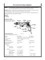
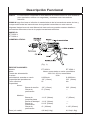
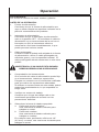
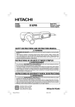
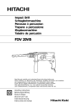
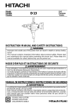
ET-3505-J 1/2-INCH AND
ET-3506-J 3/8-INCH DRILL
CAUTION
RISK OF INJURY!
READ MANUAL BEFORE OPERATING!
THIS MANUAL IS AN IMPORTANT PART OF THE DRILL
AND SHOULD REMAIN WITH THIS UNIT WHEN YOU SELL OR RENT IT.
1/2-Inch and 3/8-Inch Drill Operator's Manual
1
Introduction
Congratulations on the purchase of your new drill! You can be assured your drill was
constructed and designed with quality and performance in mind. Each component has
been rigorously tested to ensure the highest level of acceptance.
This operator's manual was compiled for your benefit. By reading and following the simple
safety, installation, operation, maintenance and troubleshooting steps described in this
manual, you will receive years of trouble-free operation from your new drill. The contents
of this manual are based on the latest product information available at the time of
publication. The manufacturer reserves the right to make changes in price, color, materials, equipment, specifications or models at any time without notice.
Once the unit has been removed from the box, immediately write in the serial number of your
unit in the space provided below.
SERIAL NUMBER_________________________________
Inspect for signs of obvious or concealed freight damage. If damage does exist, file a claim
with the transportation company immediately. Be sure that all damaged parts are replaced and
that the mechanical problems are corrected prior to operation of the unit. If you require service,
contact your Customer Service.
Mi-T-M® Corporation, 8650 Enterprise Drive, Peosta, IA 52068
1-877-JD-KLEEN / (1-877-535-5336) Fax 563-556-1235
Monday - Friday 8:00 a.m. - 5:00 p.m. CST
Please have the following information available for all service calls:
1.
Model Number
2.
Serial Number
3.
Date and Place of Purchase
WARNING
WEAR RESPIRATORY PROTECTION
Some dust created by power sanding, sawing, grinding, drilling and other construction
activities contain chemicals known to the State of California to cause cancer, birth
defects or other reproductive harm. Some examples of these chemicals are:
•
Lead from lead-base paints,
•
Crystalline Silica from bricks, cement and other masonry products, and
•
Arsenic and Chromium from chemically-treated lumber.
Your risk from these exposures varies, depending on how often you do this type of work.
To reduce your exposure to these chemicals, work in a well ventilated area and work
with approved safety equipment, such as those dust masks that are specially designed
to filter out microscopic particles.
2
1/2-Inch and 3/8-Inch Drill Operator's Manual
Table of Content
SAFETY .................................................................................................................. 4-8
GENERAL SAFETY RULES .................................................................. 4-8
FUNCTIONAL DESCRIPTION ...............................................................................
MODEL ...................................................................................................
NAME OF PARTS ..................................................................................
SPECIFICATIONS .................................................................................
9
9
9
9
OPERATION ...........................................................................................................
APPLICATIONS .....................................................................................
PRE-OPERATION .................................................................................
OPERATION ..........................................................................................
10-12
10
10-11
12
MAINTENANCE AND INSPECTION .....................................................................
MAINTENANCE AND INSPECTION .....................................................
SERVICE AND REPAIRS ......................................................................
MODIFICATIONS ...................................................................................
STANDARD ACCESSORIES ................................................................
13-14
13
13
13
14
NOTES ................................................................................................................... 15
FRENCH ................................................................................................................. 16-29
SPANISH ................................................................................................................ 30-43
1/2-Inch and 3/8-Inch Drill Operator's Manual
3
Safety
RECOGNIZE SAFETY INFORMATION
This is the safety alert symbol. When you see this symbol on
your tool or in this manual, be alert to the potential for
personal injury.
Follow recommended precautions and safe operating
practices.
UNDERSTAND SIGNAL WORDS
A "DANGER, WARNING or CAUTION" safety warning will be
surrounded by a "SAFETY ALERT BOX." This box is used to
designate and emphasize Safety Warnings that must be
followed when operating this tool.
Accompanying the Safety Warnings are "signal words" which
designate the degree or level of hazard seriousness. The
"signal words" used in this manual are as follows:
DANGER: Indicates an imminently hazardous situation
which, if not avoided, WILL result in death or
serious injury.
WARNING: Indicates a potentially hazardous situation
which, if not avoided, COULD result in death or
serious injury.
CAUTION: Indicates a potentially hazardous situation
which, if not avoided MAY result in minor or
moderate injury.
GENERAL SAFETY RULES
WARNING: Read and understand all
instructions.
Failure to follow all
instructions listed below, may
result in electric shock, fire and/
or serious personal injury.
SAVE THESE INSTRUCTIONS
4
1/2-Inch and 3/8-Inch Drill Operator's Manual
WARNING
KEEP YOUR WORK AREA CLEAN AND WELL
LIT. Cluttered benches and dark areas invite
accidents.
DO NOT OPERATE POWER TOOLS IN EXPLOSIVE ATMOSPHERES, SUCH AS IN THE PRESENCE OF FLAMMABLE LIQUIDS, GASES, OR
DUST. Power tools create sparks which may ignite
the dust of fumes.
KEEP BYSTANDERS CHILDREN, AND VISITORS
AWAY WHILE OPERATING A POWER TOOL.
Distractions can cause you to lose control.
ELECTRICAL SAFETY
DOUBLE INSULATED TOOLS ARE EQUIPPED
WITH A POLARIZED PLUG (ONE BLADE IS
WIDER THAN THE OTHER.) THIS PLUG WILL FIT
IN A POLARIZED OUTLET ONLY ONE WAY. IF
THE PLUG DOES NOT FIT FULLY IN THE
OUTLET, REVERSE THE PLUG. IF IT STILL
DOES NOT FIT, CONTACT A QUALIFIED
ELECTRICIAN TO INSTALL A POLARIZED
OUTLET. DO NOT CHANGE THE PLUG IN ANY
WAY. Double Insulation
eliminates the need for
the three wire grounded power cord and grounded
power supply system.
AVOID BODY CONTACT WITH GROUNDED
SURFACES SUCH AS PIPES, RADIATORS,
RANGES AND REFRIGERATORS. There is an
increased risk of electric shock if your body is
grounded.
DO NOT EXPOSE POWER TOOLS TO RAIN OR
WET CONDITIONS. Water entering a power tool
will increase the risk of electric shock.
DO NOT ABUSE THE CORD. NEVER USE THE
CORD TO CARRY THE TOOLS OR PULL THE
PLUG FROM A RECEPTACLE. KEEP CORD
AWAY FROM HEAT, OIL, SHARP EDGES OR
MOVING PARTS. REPLACE DAMAGED CORDS
IMMEDIATELY. Damaged cords increase the risk of
electric shock.
WHEN OPERATING A POWER TOOL OUTSIDE,
USE AN OUTDOOR EXTENSION CORD MARKED
“W-A” OR “W”. These cords are rated for outdoor
use and reduce the risk of electric shock.
1/2-Inch and 3/8-Inch Drill Operator's Manual
5
WARNING
PERSONAL SAFETY
STAY ALERT, WATCH WHAT YOU ARE DOING AND USE COMMON SENSE
WHEN OPERATING A POWER TOOL. DO NOT USE TOOL WHILE TIRED OR
UNDER THE INFLUENCE OF DRUGS, ALCOHOL, OR MEDICATION. A moment of
inattention while operating power tools may result in serious personal injury.
DRESS PROPERLY. DO NOT WEAR LOOSE CLOTHING OR JEWELRY. CONTAIN
LONG HAIR. KEEP YOUR HAIR, CLOTHING AND GLOVES AWAY FROM MOVING
PARTS. Loose clothes, jewelry, or long hair can be caught in moving parts.
Avoid accidental starting. Be sure switch is off before plugging in. Carrying tools
with your finger on the switch or plugging in tools that have the switch on invites
accidents.
Remove adjusting keys or wrenches before turning the tool on. A wrench or a key that
is left attached to a rotating part of the tool may result in personal injury.
DO NOT OVERREACH. KEEP PROPER FOOTING AND BALANCE AT ALL TIMES.
Proper footing and balance enables better control of the tool in unexpected situations.
USE SAFETY EQUIPMENT. ALWAYS WEAR PROTECTIVE GLASSES. Dust mask,
nonskid safety shoes, hard hat, or ear plugs must be used for appropriate conditions.
TOOL USE AND CARE
USE CLAMPS OR OTHER PRACTICAL WAY TO SECURE AND SUPPORT THE
WORKPIECE TO A STABLE PLATFORM. Holding the work by hand or against your
body is unstable and may lead to loss of control.
DO NOT FORCE TOOL. USE THE CORRECT TOOL FOR YOUR APPLICATION.
The correct tool will do the job better and safer at the rate for which it is designed.
DO NOT USE TOOL IF SWITCH DOES NOT TURN IT ON OR OFF. Any tool that
cannot be controlled with the switch is dangerous and must be repaired.
DISCONNECT THE PLUG FROM THE POWER SOURCE BEFORE MAKING ANY
ADJUSTMENTS, CHANGING ACCESSORIES, OR STORING THE TOOL. Such
preventive safety measures reduce the risk of starting the tool accidentally.
STORE IDLE TOOLS OUT OF REACH OF CHILDREN AND OTHER UNTRAINED
PERSONS. Tools are dangerous in the hands of untrained users.
MAINTAIN TOOLS WITH CARE. KEEP CUTTING TOOLS SHARP AND CLEAN.
Properly maintained tools, with sharp cutting edges are less likely to bind and are
easier to control.
CHECK FOR MISALIGNMENT OR BINDING OF MOVING PARTS, BREAKAGE OF
PARTS, AND ANY OTHER CONDITION THAT MAY AFFECT THE TOOL'S OPERATION. IF DAMAGED, HAVE THE TOOL SERVICED BY A JOHN DEERE AUTHORIZED SERVICE CENTER BEFORE USING. Many accidents are caused by poorly
maintained tools.
USE ONLY ACCESSORIES THAT ARE RECOMMENDED BY THE MANUFACTURER FOR YOUR MODEL. Accessories that may be suitable for one tool, may
become hazardous when used with another tool.
SPECIFIC SAFETY RULES AND SYMBOLS
1. HOLD TOOLS BY INSULATED GRIPPING SURFACES WHEN PERFORMING
AN OPERATION WHERE THE CUTTING TOOL MAY CONTACT HIDDEN
WIRING OR ITS OWN CORD. Contact with a “live” wire will make exposed metal
parts of the tool “live” and shock the operator.
2. ALWAYS wear ear plugs when using the tool for extended periods. Prolonged
exposure to high intensity noise can cause hearing loss.
3. NEVER touch the tool bit with bare hands after operation.
4. NEVER wear gloves made of material liable to roll up such as cotton, wool, cloth
or string, etc
6
1/2-Inch and 3/8-Inch Drill Operator's Manual
WARNING
SPECIFIC SAFETY RULES AND SYMBOLS (CONTINUED)
5.
For ET-3506-J: ALWAYS securely grip the Drill.
For ET-3505-J: ALWAYS attach the side handle
and securely grip the Drill.
6. NEVER touch moving parts.
NEVER place your hands, fingers or other body
parts near the tool’s moving parts.
7. NEVER operate without all guards in place.
NEVER operate this tool without all guards or safety features in place and in proper
working order. If maintenance or servicing requires the removal of a guard or safety
feature, be sure to replace the guard or safety feature before resuming operation of
the tool.
8. Use right tool.
Don’t force small tool or attachment to do the job of a heavy-duty tool.
Don’t use tool for purpose not intended —for example— don’t use circular saw for
cutting tree limbs or logs.
9. NEVER use a power tool for applications other than those specified.
NEVER use a power tool for applications other than those specified in the
Instruction Manual.
10. Handle tool correctly.
Operate the tool according to the instructions provided herein. Do not drop or throw
the tool. NEVER allow the tool to be operated by children, individuals unfamiliar
with its operation or unauthorized personnel.
11. Keep all screws, bolts and covers tightly in place.
Keep all screws, bolts, and plates tightly mounted. Check their condition
periodically.
12. Do not use power tools if the plastic housing or handle is cracked.
Cracks in the tool’s housing or handle can lead to electric shock. Such tools should
not be used until repaired.
13. Blades and accessories must be securely mounted to the tool.
Prevent potential injuries to youself or others. Blades, cutting implements and
accessories which have been mounted to the tool should be secure and tight.
14. Keep motor air vent clean.
The tool’s motor air vent must be kept clean so that air can freely flow at all times.
Check for dust build-up frequently.
15. Operate power tools at the rated voltage.
Operate the power tool at voltages specified on its nameplate.
If using the power tool at a higher voltage than the rated voltage, it will result in
abnormally fast motor revolution and may damage the unit and the motor may burn
out.
16. NEVER use a tool which is defective or operating abnormally.
If the tool appears to be operating unusually, making strange noises, or otherwise
appears defective, stop using it immediately and arrange for repairs by an
authorized JOHN DEERE DEALER.
17. NEVER leave tool running unattended. Turn power off.
Don’t leave tool until it comes to a complete stop.
18. Carefully handle power tools.
Should a power tool be dropped or struck against hard materials inadvertently, it
may be deformed, cracked, or damaged.
1/2-Inch and 3/8-Inch Drill Operator's Manual
7
WARNING
SPECIFIC SAFETY RULES AND SYMBOLS (CONTINUED)
19. DO NOT WIPE PLASTIC PARTS WITH SOLVENT.
Solvents such as gasoline, thinner benzine, carbon tetrachloride, and alcohol may
damage and crack plastic parts. Do not wipe them with such solvents.
Wipe plastic parts with a soft cloth lightly dampened with soapy water and dry
thoroughly.
20. ALWAYS wear eye protection that meets the requirement of the latest revision of
ANSI Standard Z87.1.
21. ALWAYS be careful with buried objects such as under
ground wiring. Touching active wiring or electric cable
with this tool, may cause an electric shock. Confirm if
there are any buried objects such as electric cable
within the wall, floor or ceiling where you are going
to operate here after.
22. Definitions for symbols used on this tool
Volts = V
Hertz = Hz
Amperes = A
No load speed = no
Watt = W
Class II Construction =
Revolutions per minute = ---/min
CAUTION
DOUBLE INSULATION FOR SAFER OPERATION
To ensure safer operation of this power tool, JOHN DEERE has adopted a double
insulation design. “Double insulation “ means that two physically separated insulation
systems have been used to insulate the electrically conductive materials connected to
the power supply from the outer frame handled by the operator. Therefore, either the
symbol “
” or the words “Double insulation” appear on the power tool or on the
nameplate.
Although this system has no external grounding, you must still follow the normal
electrical safety precautions given in this Instruction Manual, including not using the
power tool in wet environments.
To keep the double insulation system effective, follow these precautions:
a. Only JOHN DEERE AUTHORIZED DEALER should disassemble or assemble
this power tool, and only genuine JOHN DEERE replacement parts should be
installed.
b. Clean the exterior of the power tool only with a soft cloth moistened with soapy
water, and dry thoroughly.
Never use solvents, gasoline or thinners on plastic components; otherwise the plastic
may dissolve.
SERVICE
TOOL SERVICE MUST BE PERFORMED ONLY BY A JOHN DEERE AUTHORIZED
SERVICE CENTER. Service or maintenance performed by unqualified personnel could
result in a risk of injury.
WHEN SERVICING A TOOL, USE ONLY IDENTICAL REPLACEMENT PARTS.
FOLLOW INSTRUCTIONS IN THE MAINTENANCE SECTION OF THIS MANUAL.
Use of unauthorized parts or failure to follow Maintenance Instruction may create a risk
of electric shock or injury.
SAVE THESE INSTRUCTIONS AND MAKE THEM AVAILABLE TO
OTHER USERS AND OWNERS OF THIS TOOL!
8
1/2-Inch and 3/8-Inch Drill Operator's Manual
Functional Description
NOTE:
The information contained in this Instruction Manual is designed to assist
you in the safe operation and maintenance of the power tool.
NEVER operate, or attempt any maintenance on the tool unless you have first read
and understood all safety instructions contained in this manual.
Some illustrations in this Instruction Manual may show details or attachments that
differ from those on your own power tool.
MODEL:
ET-3505-J
ET-3506-J
NAME OF PARTS:
1/2-Inch Drill (ET-3505-J)
3/8-Inch Drill (ET-3506-J)
SPECIFICATIONS:
Drill ET-3505-J and ET-3506-J:
Model
Motor
Power Source
Current
No-Load Speed
Drill Chuck Capacity
Electric Brake
Capacity:
SteelTwist Bit
Hole Saw
WoodFlat Spade Bit
Auger Bit
Self Feed Bit
Hole Saw
Weight (without cord)
(Fig. 1)
ET-3505-J
ET-3506-J
Single Phase, Series Commutator Motor
Single Phase 120V AC 60 Hz
9.0A
0-850/min.
0-3000/min
1/2" (13mm)
3/8" (10mm)
Yes
No
1/2" (13mm)
2" (51mm)
3/8" (10mm)
—
1-1/2" (38mm)
1-1/4" (32mm)
2-1/8" (54mm)
4" (102mm)
4.6 lbs (2.1kg)
1" (25mm)
—
—
1-1/8" (29mm)
4.0 lbs (1.8kg)
1/2-Inch and 3/8-Inch Drill Operator's Manual
9
Operation
APPLICATIONS:
Boring holes in metal, wood and plastic.
PRE-OPERATION:
1. Power source:
Ensure that the power source to be utilized conforms
to the power source requirements specified on the
product nameplate.
2.
Power switch:
Ensure that the switch is in the OFF position. If the
plug is connected to a receptacle while the switch is
in the ON position, the power tool will start operating
immediately and can cause serious injury.
3.
Extension cord:
When the work area is far away from the power
source, use an extension cord of sufficient thickness
and rated capacity. The extension cord should be
kept as short as possible.
WARNING:
DAMAGED CORD MUST BE
REPLACED OR REPAIRED.
4.
Check the receptacle:
If the receptacle only loosely accepts the plug, the
receptacle must be repaired. Contact a licensed
electrician to make appropriate repairs.
If such a faulty receptacle is used, it may cause
overheating, resulting in a serious hazard.
5.
Check your work environment:
Confirm that the work site is placed under
appropriate conditions conforming to prescribed
precautions.
6.
Selecting the appropriate drill bit:
a. When boring metal or plastic, use an ordinary
metalworking drill bit.
b. When boring wood, use an ordinary woodwork
ing drill bit.
However, when drilling 1/4" (6.5 mm) or smaller
holes, use a metalworking drill bit.
10
1/2-Inch and 3/8-Inch Drill Operator's Manual
Operation
PRE-OPERATION (CONTINUED):
7.
Mounting and dismounting of the bit (Fig. 2)
a. Open the chuck jaws, and insert the bit
into the chuck.
b. Place the chuck wrench in each of the
three holes in the chuck, and turn it in the
clockwise direction (viewed from the front
side). Tighten securely.
c. To remove the bit, place the chuck
wrench into one of the holes in the chuck
and turn it in the counterclockwise
direction.
8.
Installing the side handle for ET-3505-J:
A Side handle is supplied with drill. It can be
installed on either side of the tool for right or
left handed use.
To install the side handle, thread it into the
socket on the desired side of the tool and
tighten it securely. (Fig. 3)
9.
Check the rotational direction (Fig. 4)
The bit rotates clockwise (viewed from the
rear side) by pushing the R-side of the push
button.
The L-side of the push button is pushed to
turn the bit counterclockwise. (The (L) and (R)
marks are provided on the body.)
(Fig. 2)
(Fig. 3)
(Fig. 4)
1/2-Inch and 3/8-Inch Drill Operator's Manual
11
Operation
OPERATION:
CAUTION:
TO PREVENT ACCIDENTS, MAKE SURE TO TURN THE SWITCH
OFF AND DISCONNECT THE PLUG FROM THE RECEPTACLE
WHEN THE DRILL BITS AND OTHER VARIOUS PARTS ARE
INSTALLED OR REMOVED. THE POWER SWITCH SHOULD
ALSO BE TURNED OFF DURING A WORK BREAK AND AFTER
WORK.
1.
Switch operation:
a. When the trigger switch is depressed, the tool rotates. When the trigger is
released, the tool stops.
b. The rotational speed of the drill can be controlled by varying the amount that
the Trigger switch is pulled. Speed is low when the trigger switch is pulled
slightly and increases as the trigger switch is pulled more.
c. Pulling the trigger and pushing the stopper, it keeps the switched-on condition
which is convenient for continuous running. When switching off, the stopper
can be disconnected by pulling the trigger again.
2.
Electric brake (ET-3505-J):
When releasing the trigger of the switch, the brake will be applied for immediate
stopping.
CAUTION:
AS THERE IS SOME REACTION WHEN THE BRAKE
FUNCTIONS, BE SURE TO HOLD THE DRILL SECURELY.
WHEN THE BRAKE BECOMES INEFFECTIVE, SEND THE TOOL
TO AN AUTHORIZED JOHN DEERE DEALER.
3.
12
Drilling:
a. When drilling, start the drill slowly, and gradually increasing speed as you drill.
b. Always apply pressure in a straight line with the bit. Use enough pressure to
keep drilling, but do not push hard enough to stall the motor or deflect the bit.
c. To minimize stalling or breaking through the material, reduce pressure on drill
and ease the bit through the last part of the hole.
d. If the drill stalls, release the trigger immediately, remove the bit from the work
and start again. Do not click the trigger on and off in an attempt to start a
stalled drill. This can damage the drill.
e. The larger the drill bit diameter, the larger the reactive force on your arm.
Be careful not to lose control of the drill because of this reactive force.
To maintain firm control, establish a good foothold, use side handle, hold the
drill tightly with both hands, and ensure that the drill is vertical to the material
being drilled.
1/2-Inch and 3/8-Inch Drill Operator's Manual
Maintenance and Inspection
MAINTENANCE AND INSPECTION:
WARNING:
BE SURE TO SWITCH POWER OFF AND DISCONNECT THE
PLUG FROM THE RECEPTACLE DURING MAINTENANCE AND
INSPECTION.
1.
Inspecting the drill bits:
Since use of a dull tool will cause motor malfunctioning and degraded efficiency,
replace the drill bit with a new one or resharpening without delay when abrasion is
noted.
2.
Inspecting the screws:
Regularly inspect all screws and ensure that they are fully tightened. Should any of
the screws be loosened, retighten them immediately.
WARNING:
USING THIS DRILL WITH LOOSENED SCREWS IS EXTREMELY
DANGEROUS.
3.
Keeping after use:
When not in use, the Power tool should be kept in a dry place out of the reach of
children.
4.
Inspecting the carbon brushes:
For your continued safety and electrical shock protection, carbon brush inspection
and replacement on this tool should ONLY be performed by an AUTHORIZED
JOHN DEERE DEALER.
5.
Maintenance of the motor:
The motor unit winding is the very “heart”’ of the power tool. Exercise due care to
ensure the winding does not become damaged and/or wet with oil or water.
SERVICE AND REPAIRS:
All quality power tools will eventually require servicing or replacement of parts because
of wear from normal use. To assure that only authorized replacement parts will be used,
all service and repairs must be performed by an AUTHORIZED JOHN DEERE DEALER,
ONLY.
MODIFICATIONS:
JOHN DEERE Power Tools are constantly being improved and modified to incorporate
the latest technological advancements.
Accordingly, some parts (i.e. code numbers and/or design) may be changed without prior
notice.
1/2-Inch and 3/8-Inch Drill Operator's Manual
13
Maintenance and Inspection
STANDARD ACCESSORIES:
WARNING: ALWAYS USE ONLY AUTHORIZED JOHN DEERE
REPLACEMENT PARTS AND ACCESSORIES. NEVER USE
REPLACEMENT PARTS OR ACCESSORIES WHICH ARE NO INTENDED
FOR USE WITH THIS TOOL. CONTACT JOHN DEERE IF YOU ARE NOT
SURE WHETHER IT IS SAFE TO USE A PARTICULAR REPLACEMENT
PART OR ACCESSORY WITH YOUR TOOL. THE USE OF ANY OTHER
ATTACHMENT OR ACCESSORY CAN BE DANGEROUS AND COULD
CAUSE INJURY OR MECHANICAL DAMAGE.
ET-3505-J:
1. Side Handle
2. Chuck Wrench
1
1
ET-3506-J:
1. Chuck Wrench
1
NOTE:
14
Accessories are subject to change without any obligation on the part of
JOHN DEERE.
1/2-Inch and 3/8-Inch Drill Operator's Manual
Notes
Manuel Opérateur
15
Introduction
Félicitations de l'achat de votre nouveau la clé à outil! Vous pouvez être assuré que votre
nouveau la outil a été construit avec le plus haut niveau de précision et de fiabilité. Chaque
composant a été rigoureusement testé par des techniciens pour assurer la qualité, la durabilité
et la performance de ce outil.
Ce manuel opérateur a été dressé pour que vous en retiriez le meilleur parti. Par la lecture
et l'application des mesures simples de sécurité, d'installation et d'opération, d'entretien et
de dépannage décrites dans ce manuel, votre nouveau outil. Fonctionnera sans faille
pendant de nombreuses années. Le contenu de ce manuel est basé sur la dernière
information disponible du produit au moment de la publication. Félicitations se réserve le
droit d'effectuer des changements de prix, de couleur, de matériaux, d'équipement, de
caractéristiques ou de modèles à tout moment sans communication préalable.
Une fois l'appareil déballé, écrivez immédiatement le numéro de série de votre appareil dans
l'espace çidessous.
NUMÉRO DE SÉRIE_________________________________
Assurez vous qu'il n'y a pas de signes de dommages évidents ou cachés suite au transport.
En cas de dommage, remplissez immédiatement une réclamation avec la compagnie de
transport. Assurez vous que toutes les pièces endommagées sont remplacees et les
problémes mécaniques et électriques corrigés avant l'utilisation de l'appareil. Si vous avez
besoin d'assistance, entrez en contact avec votre service clientèle.
Mi-T-M® Corporation, 8650 Enterprise Drive, Peosta, IA 52068-0050
Tél.: JD-KLEEN (1-877-535-5336) Fax 563-556-1235
du lundi au vendredi de 8h00 à 17h, CST (heure centrale)
Veuillez avoir les informations suivantes disponibles pour toute intervention:
1.
Numéro de modèle
2.
Numéro de série
3.
Date et lieu d'achat
ADVERTISSEMENT
LE PORT D’UNE PROTECTION RESPIRATOIRE EST RECOMMANDÉ
Certaines poussières produites par le sablage, le sciage, le broyage, le perçage, et
autres activités de construction contiennent des produits chimiques connus par l'Etat de
Californie pour cause de cancer, de défauts de naissance ou de problèmes de
reproduction. Des exemples de ces produits chimiques sont:
•
•
•
Du plomb provenant de peintures à base de plomb.
De la silice de Crystalline provenant de briques, de ciment et d’autres produits de
maçonnerie.
De l’arsenic et du chrome provenant de bois de charpente traité chimiquement.
Votre risque de ces contacts varie selon le temps passé à faire ce genre de travail.
Pour réduire votre exposition à ces produits chimiques, travailler dans un endroit bien
aéré et avec un équipement de sécurité approuvé tels que les masques de poussière
conçus spécialement pour filtrer les particules microscopiques.
16
Manuel Opérateur
Table Des Matieres
SÉCURITÉ .............................................................................................................. 18-23
SIGNIFICATION DES MOTS D’AVERTISSEMENT ............................. 18-23
DESCRIPTION FONCTIONNELLE .......................................................................
MAQUETTE ...........................................................................................
NOM DES PARTIES ..............................................................................
UTILISATIONS .......................................................................................
SPECIFICATIONS .................................................................................
24
24
24
24
24
UTILISATION .........................................................................................................
ACCESSOIRES STANDARD ................................................................
AVANT L'UTILISATION .........................................................................
UTILISATION .........................................................................................
25-27
25
25-26
27
ENTRETIEN ET INSPECTIONS ............................................................................
ENTRETIEN ET INSPECTIONS ...........................................................
ENTRETIEN ET RÉPARATION ............................................................
MODIFICATIONS ...................................................................................
ACCESSOIRES STANDARD ................................................................
28-29
28
28
28
29
Manuel Opérateur
17
Sécurité
RECONNAÎTRE LES SYMBOLES DE MISE EN
GARDE
Voici le symbole de mise en garde. Lorsqu'il apparaît sur la
outil ou dans la présente publication, c'est pour prévenir d'un
risque potentiel de blessure.
Respecter tous les conseil de sécurité ainsi que les
consignes générales de prévention des accidents.
COMPRENDRE LES TERMES DE MISE EN
GARDE
Les
avertissements
de
sécurité
"DANGER,
AVERTISSEMENT ou ATTENTION" seront entourés par
un "ENCADRE ALERTE SECURITE".Cet encadré est utilisé
pour indiquer et souligner les avertissements de sécurité qui
doivent être suivis en actionnant d'outils. En plus des
avertissements de sécurité, des "mots d'alerte" sont utilisés
pour indiquer le degré ou niveau de risque. Les "mots
d'alerte" utilisés dans ce manuel sont comme suit:
DANGER
AVERTISSEMENT
ATTENTION
DANGER: Indique une situation au danger
imminent qui, si elle n'est pas évitée,
ENTRAINERA la mort ou des blessures
graves.
AVERTISSEMENT: Indique une situation
potentiellement dangereuse qui, si elle
n'est pas évitée, POURRAIT entraîner la
mort ou des blessures graves.
ATTENTION: Indique une situation
potentiellement dangereuse, qui, si elle
n'est pas évitée, PEUT entraîner des
blessures mineures ou peu graves et des
dégats au compresseur.
REGLES GENERALE DE SECURITE
AVERTISSEMENT:
Lire et
coxmprendre toutes les instructions. Un
non respect de toutes les intrucitons
ci-dessous peut entraîner une
électrocution, un incedie et/ou de
sérieuses blessures personnelles.
CONSERVER CES INSTRUCTIONS
18
Manuel Opérateur
AVERTISSEMENT
GARDER LA ZONE DE TRAVAIL PROPRE ET BIEN
ÉCLAIRÉE. Les établis mal rangés et les zones sombres
invitent aux accidents.
NE PAS UTILISER LES OUTILS MOTORISÉS DANS
UNE ATMOSPHÈRE EXPLOSIVE, TELLE QU’EN
PRÉSENCE DE LIQUIDES INFLAMMABLES, DE GAZ
OU DE POUSSIÈRES. Les outils motorisés créent des
étincelles qui risquent d’enflammer la poussière ou les
vapeurs.
TENIR LES SPECTATEURS, LES ENFANTS ET LES
VISITEURS ÉLOIGNÉS, LORS DE L’UTILISATION DE
L’OUTIL MOTORISÉ. Une distraction peut faire perdre le
contrôle de la machine.
SÉCURITÉ ÉLECTRIQUE
LES OUTILS À DOUBLE ISOLATION SONT ÉQUIPÉS
D’UNE FICHE POLARISÉE (UNE LAME EST PLUS
LARGE QUE L’AUTRE). CETTE FICHE NE PÉNÉTRERA
DANS UNE PRISE SECTEUR POLARISÉE QUE DANS
UN SENS. SI LA FICHE NE RENTRE PAS
COMPLÈTEMENT DANS LA PRISE, LA RETOURNER.
SI ELLE NE RENTRE TOUJOURS PAS, CONTACTER
UN ÉLECTRICIEN QUALIFIÉ POUR INSTALLER UNE
PRISE POLARISÉE. NE PAS MODIFIER LA FICHE
D’AUCUNE FAÇON. La double isolation
élimine le
besoin d’un cordon d’alimentation à trois fils et d’un
système d’alimentation avec mises à la terre.
EVITER TOUT CONTACT CORPOREL AVEC LES
SURFACES MISES À LA TERRE TELLES QUE LES
CANALISATIONS, LES RADIATEURS, LES RÉCHAUDS
ET LES RÉFRIGÉRATEURS. Il y a un risque accru
d’électrocution si son corps est mis à la terre.
NE PAS EXPOSER LES OUTILS MOTORISÉS À LA
PLUIE OU À L’HUMIDITÉ. De l’eau pénétrant à l’intérieur
de l’outil motorisé augmente le risque d’électrocution.
NE PAS MALTRAITER LE CORDON D’ALIMENTATION.
NE JAMAIS UTILISER LE CORDON POUR PORTER
LES OUTILS OU TIRER SUR LA FICHE DU
RÉCEPTACLE. GARDER LE CORDON À L’ÉCART DE
LA CHALEUR, DE L’HUILE, DES ARÊTES COUPANTES
OU DES PIÈCES EN MOUVEMENT. REMPLACER LES
CORDONS ENDOMMAGÉS IMMÉDIATEMENT. Des
cordons endommagés augmentent le risque
d’électrocution.
LORS DE L’UTILISATION D’UN OUTIL MOTORISÉ,
UTILISER UN CORDON DE RALLONGE EXTÉRIEUR
MARQUÉ “W-A” OU “W”. Ces cordons sont prévus pour
une utilisation extérieure et réduisent les risques
d’électrocution.
Manuel Opérateur
19
AVERTISSEMENT
SÉCURITÉ PERSONNELLE
RESTER SUR SES GARDES, REGARDER CE QUE L’ON FAIT ET UTILISER SON
SENS COMMUN LORS DE L’UTILISATION D’UN OUTIL MOTORISÉ. NE PAS
UTILISER UN OUTIL EN ÉTAT DE FATIGUE OU SOUS L’INFLUENCE DE
DROGUES, D’ALCOOL OU DE MÉDICAMENTS. Un moment d’inattention lors de
l’utilisation de l’outil motorisé peut entraîner de sérieuses blessures personnelles.
S’HABILLER CORRECTEMENT. NE PAS PORTER DES VÊTEMENTS LARGES OU
DES BIJOUX. ATTACHER LES CHEVEUX LONGS. TENIR SES CHEVEUX,
VÊTEMENTS ET SES GANTS ÉLOIGNÉS DES PARTIES MOBILES. Les vêtements
larges, les bijoux et les cheveux longs peuvent se prendre dans les parties mobiles.
EVITER TOUT DÉMARRAGE ACCIDENTEL. S’ASSURER QUE LE
L’INTERRUPTEUR D’ALIMENTATION EST SUR LA POSITION D’ARRÊT AVANT
DE BRANCHER LA MACHINE. Transporter l’appareil avec les doigts sur l’interrupteur
d’alimentation ou brancher un outil avec l’interrupteur sur la position marche invite aux
accidents.
RETIRER LES CLEFS D’AJUSTEMENT OU LES COMMUTATEURS AVANT DE
METTRE L’OUTIL SOUS TENSION. Une clef qui est laissée attachée à une partie
tournante de l’outil peut provoquer une blessure personnelle.
NE PAS TROP PRÉSUMER DE SES FORCES. GARDER EN PERMANENCE UNE
POSITION ET UN ÉQUILIBRE CORRECT. Une position et un équilibre correct
permettent un meilleur contrôle de l’outil dans des situations inattendues.
UTILISER UN ÉQUIPEMENT DE SÉCURITÉ. TOUJOURS PORTER DES LUNETTES DE PROTECTION. Un masque à poussière, des chaussures de sécurité
antidérapantes, un chapeau dur et des bouchons d’oreille doivent être utilisés dans
les conditions appropriées.
UTILISATION DE L’OUTIL ET ENTRETIEN
UTILISER UN ÉTAU OU TOUTES AUTRES FAÇONS DE FIXER ET MAINTENIR LA
PIÈCE À USINER SUR UNE PLATE-FORME STABLE. Tenir la pièce avec la main
ou contre son corps est instable et peut conduire à une perte de contrôle de l’outil.
NE PAS FORCER SUR L’OUTIL. UTILISER L’OUTIL CORRECT POUR
L’APPLICATION SOUHAITÉE. L’outil correct réalisera un meilleur et plus sûr travail
dans le domaine pour lequel il a été conçu. RANGER LES OUTILS INUTILISÉS
HORS DE LA PORTÉE DES ENFANTS ET DES AUTRES PERSONNES
INEXPÉRIMENTÉES. Les outil qui ne peut pas être commandé avec un interrupteur
est dangereux et doit être réparé.
DÉCONNECTER LA FICHE DE LA SOURCE D’ALIMENTATION AVANT DE
RÉALISER TOUT AJUSTEMENT, CHANGEMENT D’ACCESSOIRES OU POUR
RANGER L’OUTIL. De telles mesures de sécurité réduisent le risque que l’outil ne
démarre accidentellement.
RANGER LES OUTILS INUTILISÉS HORS DE LA PORTÉE DES ENFANTS ET DES
AUTRES PERSONNES INEXPÉRIMENTÉES. Les outils sont dangereux dans les
mains de personnes inexpérimentées.
CONSERVER LES OUTILS AVEC SOIN. GARDER LES OUTILS DE COUPE
AIGUISÉS ET PROPRES. Des outils bien entretenus, avec des lames coupantes
aiguisées risquent moins de se gripper et sont plus faciles à contrôler.
VÉRIFIER LES DÉFAUTS D’ALIGNEMENT OU GRIPPAGE DES PARTIES MOBILES, LES RUPTURES DES PIÈCES ET TOUTES LES AUTRES CONDITIONS
QUI PEUVENT AFFECTER LE FONCTIONNEMENT DES OUTILS. EN CAS DE
DOMMAGE, FAIRE RÉPARER L’OUTIL PAR UN CENTRE DE SERVICE JOHN
DEERE AUTORISÉ AVANT DE L’UTILISER. Beaucoup d’accidents sont causés par
des outils mal entretenus.
Utiliser uniquement les accessoires recommandés par le fabricant pur le modèle
utilisé. Des accessoires qui peuvent convenir à un outil, peuvent devenir dangereux
lorsqu’ils sont utilisés avec un autre outil.
20
Manuel Opérateur
AVERTISSEMENT
REGLES DE SECURITE SPECIFIQUES ET SYMBOLES
1. TENIR LES OUTILS PAR LES SURFACES DE GRIPPAGE LORS
DE LA RÉALISATION D’OPÉRATION OÙ L’OUTIL DE COUPE
RISQUE D’ENTRER EN CONTACT AVEC DES CÂBLES CACHÉS
OU SON PROPRE CORDON. Un contact avec un fil “sous
tension” mettra les parties métalliques de l’outil
“sous tension” et électrocutera l’utilisateur.
2. TOUJOURS porter des bouchons d’oreille lors de
l’utilisation de l’outil pendant de longues périodes.
Une exposition prolongée à un son de forte intensité peut endommager l’ouïe de
l’utilisateur.
3. NE JAMAIS toucher la mèche avec des mains nues après l’utilisation.
4. NE JAMAIS porter de gants faits d’une matière qui risque de s’enrouler, comme du
coton, de la laine, de la toile ou de la ficelle, etc.
5. Modèle ET-3506-J: TOUJOURS tenir la perceuse fermement.
Modèle ET-3505-J: TOUJOURS fixer la poignée latérale et tenir la peroceuse
solidement.
6. NE JAMAIS toucher les parties mobiles. NE JAMAIS placer ses mains, ses doigts
ou toute autre partie de son corps près des parties mobiles de l’outil.
7. NE JAMAIS utiliser l’outil sans que tous les dispositifs de sécurité ne soient en
place.
NE JAMAIS faire fonctionner cet outil sans que tous les dispositifs et
caractéristiques de sécurité ne soient en place et en état de fonctionnement. Si un
entretien ou une réparation nécessite le retrait d’un dispositif ou d’une
caractéristique de sécurité, s’assurer de bien remettre en place le dispositif ou la
caractéristique de sécurité avant de recommencer à utiliser l’outil.
8. Utiliser l’outil correct. Ne pas forcer sur un petit outil ou accessoire pour faire le
travail d’un outil de grande puissance. Ne pas utiliser un outil pour un usage pour
lequel il n’a pas été prévu: par exemple, ne pas utiliser une scie circulaire pour
couper des branches d’arbre ou des bûches.
9. NE JAMAIS utiliser un outil motorisé pour des applications autres que celles
spécifiées. NE JAMAIS utiliser un outil motorisé pour des applications autres que
celles spécifiées dans le mode d’emploi.
10. Manipuler l’outil correctement. Utiliser l’outil de la façon indiquée dans ce mode
d’emploi. Ne pas laisser tomber ou lancer l’outil. NE JAMAIS permettre que l’outil
soit utilisé par des enfants, des personnes non familiarisées avec son
fonctionnement ou un personnel non autorisé.
11. Maintenir toutes les vis, tous les boulons et les couvercles fermement en place.
Maintenir toutes les vis, tous les boulons et les couvercles fermement montés.
Vérifier leurs conditions périodiquement.
12. Ne pas utiliser les outils motorisés si le revêtement de plastique ou la poignée est
fendu. Des fentes dans le revêtement ou la poignée peuvent entraîner une
électrocution. De tels outils ne doivent pas être utilisés avant d’être réparé.
13. Les lames et les accessoires doivent être fermement montés sur l’outil.
Eviter les blessures potentielles personnelles et aux autres. Les lames, les
instruments de coupe et les accessoires qui ont été montés sur l’outil doivent être
fixés et serrés fermement.réparer par un centre de service JOHN DEERE autorisé.
Manuel Opérateur
21
AVERTISSEMENT
14. Garder propres les évents d’air du moteur. Les évents d’air du moteur doivent être
maintenus propres de façon que l’air puisse circuler librement tout le temps.
Vérifier les accumulations de poussière fréquemment.
15. Utiliser l’outil motorisé à la tension nominale. Utiliser l’outil motorisé à la tension
spécifiée sur sa plaque signalétique. Si l’on utilise l’outil motorisé avec une
tension supérieure à la tension nominale, il en résultera une rotation
anormalement trop rapide du moteur et cela risque d’endommager l’outil et le
moteur risque de griller.
16. NE JAMAIS utiliser un outil défectueux ou qui fonctionne anormalement. Si l’outil
n’a pas l’air de fonctionner normalement, fait des bruits étranges ou sans cela
paraît défectueux, arrêter de l’utiliser immédiatement et le faire réparer par un
centre de service JOHN DEERE autorisé.
17. NE JAMAIS laisser fonctionner l’outil sans surveillance. Le mettre hors tension.
Ne pas abandonner l’outil avant qu’il ne soit complètement arrêté.
18. Manipuler l’outil motorisé avec précaution. Si un outil motorisé tombe ou frappe
un matériau dur accidentellement, il risque d’être déformé, fendu ou endommagé.
19. NE PAS ESSUYER LES PARTIES EN PLASTIQUE AVEC DU SOLVANT. Les
solvants comme l’essence, les diluants, la benzine, le tétrachlorure de carbone et
l’alcool peuvent endommager et fissurer les parties en plastique. Ne pas les
essuyer avec de tels solvants. Essuyer les parties en plastique avec un chiffon
doux légèrement imbibé d’une solution d’eau savonneuse et sécher
minutieusement.
20. TOUJOURS porter des lunettes de protection qui respectent les dernières
révisions du Standard ANSI Z87.1.
21. TOUJOURS vérifier s’il y a des objets encastrés
par exemple des fils électriques. Le fait de toucher
avec l’outil un fil ou un câble électrique sous tension
encastré dans le mur risque de provoquer une
décharge électrique. Vérifier s’il y des objets
encastrés, par exemple un câble électrique, dans
le mur, le plancher ou le plafond avant d’y commencer le travail.
22. Définitions pour les symboles utilisés sur cet outil
V
volts
Hz hertz
A
ampères
no vitesse sans charge
W watt
Construction de classe II
---/min
tours par minute
22
Manuel Opérateur
ATTENTION
DOUBLE ISOLATION POUR UN FONCTIONNEMENT PLUS SUR
Pour assurer un fonctionnement plus sûr de cet outil motorisé, JOHN DEERE a adopté
une conception à double insolation. “Double isolation” signifie que deux systèmes
d’isolation physiquement séparés ont été utilisés pour isoler les matériaux conducteurs
d’électricité connectés à l’outil motorisé à partir du cadre extérieur manipulé par
l’utilisateur. C’est pourquoi, le symbole “ ” ou les mots “Double insulation” (double
isolation) apparaissent sur l’outil motorisé ou sur la plaque signalétique.
Bien que ce système n’ait pas de mise à terre extérieure, il est quand même nécessaire
de suivre les précautions de sécurité électrique données dans ce mode d’emploi, ycompris de ne pas utiliser l’outil motorisé dans un environnement humide.
Pour garder le système de double isolation effectif, suivre ces précautions:
a. Seuls les CENTRES DE SERVICE AUTORISES JOHN DEERE peuvent
démonter et remonter cet outil motorisé et uniquement des pièces de
rechange JOHN DEERE garanties d’origine doivent être utilisées.
b. Nettoyer l’extérieur de l’outil motorisé uniquement avec un chiffon doux
légèrement imbibé d’une solution savonneuse et essuyer minutieusement.
Ne jamais utiliser des solvants, de l’essence ou des diluants sur les parties en plastique;
sinon le plastique risquerait de se dissoudre.
RÉPARATION
LA RÉPARATION DE L’OUTIL NE DOIT ÊTRE RÉALISÉE QUE PAR UN CENTRE DE
SERVICE JOHN DEERE AUTORISÉ. Une réparation ou un entretien réalisé par un
personnel non qualifié peut entraîner des risques de blessures.
LORS DE LA RÉPARATION D’UN OUTIL, UTILISER UNIQUEMENT DES PIÈCES DE
RECHANGE IDENTIQUES. SUIVRE LES INSTRUCTIONS DE LA SECTION
D’ENTRETIEN DE CE MODE D’EMPLOI. L’utilisation de pièces non autorisées ou un
non respect des instructions d’entretien peut créer un risque d’électrocution ou de
blessures.
CONSERVER CES INSTRUCTIONS ET LES METTRE A
LA DISPOSITION DES AUTRES UTILISATEURS ET
PROPRIETAIRES DE CET OUTIL!
Manuel Opérateur
23
Description Fonctionnelle
NOTE:
Les informations contenues dans ce mode d’emploi sont conçues pour
assister l’utilisateur dans une utilisation sans danger et un entretien de l’outil
motorisé.
NE JAMAIS utiliser ni entreprendre une révision de l’outil sans avoir d’abord lu et
compris toutes les instructions de sécurité contenues dans ce manuel.
Certaines illustrations dans ce mode d’emploi peuvent montrer des détails ou des
accessoires différents de ceux de l’outil motorisé utilisé.
MAQUETTE::
ET-3505-J
ET-3506-J
NOM DES PARTIES:
(Fig. 1)
SPECIFICATIONS:
Modèle
Moteur
Source d’alimentation
Courant
Vitesse sans charge
Capacité de mèche
Frein électrique
Capacité
Acier
Foret hélicoïdal
Scie circulaire
Bois
Foret à lame plate
Mèche creuse
Foret à avance
automatique
Scie circulaire
Poids (sans fil)
24
ET-3505-J
ET-3506-J
Moteur série monophasé à collecteur
Secteur, 120V 60 Hz, monophasé
9,0A
0-850/min.
0-3000/min.
1/2" (13mm)
3/8" (10mm)
Oui
Non
1/2" (13mm)
2" (51mm)
3/8" (10mm)
—
1-1/2" (38mm)
1-1/4" (32mm)
2-1/8" (54mm)
1" (25mm)
—
—
4" (102mm)
4,6 lbs (2,1kg)
1-1/8" (29mm)
4,0 lbs (1,8kg)
Manuel Opérateur
Utilisation
APPLICATIONS:
Perçage de trous dans métal, bois et matières plastiques.
AVANT L’UTILISATION:
1. Source d’alimentation:
S’assurer que la source d’alimentation qui doit être
utilisée est conforme à la source d’alimentation
requise spécifiée sur la plaque signalétique du
produit.
2.
Interrupteur d’alimentation:
S’assurer que l’interrupteur est sur la position OFF
(arrêt). Si la fiche est connectée sur une prise alors
que l’interrupteur est sur la position ON (marche),
l’outil motorisé démarrera immédiatement risquant
de causer de sérieuses blessures.
3.
Cordon prolongateur:
Quand la zone de travail est éloignée de la source
d’alimentation, utiliser un cordon prolongateur
d’épaisseur et de capacité nominale suffisante. Le
cordon prolongateur doit être aussi court que
possible.
AVERTISSEMENT: TOUT CORDON
ENDOMMAGÉ DEVRA ÊTRE
REMPLACÉ OU RÉPARÉ.
4.
Vérifier la prise:
Si la prise reçoit la fiche avec beaucoup de jeu, elle
doit être réparée. Contacter un électricien licencié
pour réaliser les réparations nécessaires.
Si une telle prise défectueuse est utilisée, elle peut
causer une surchauffe entraînant des dangers
sérieux.
5.
Vérifier l’environnement de travail:
Vérifier que l’état de l’aire de travail est conforme
aux précautions.
6.
Choix du foret de perçage correct:
a. Pour perçage dans métal ou plastique
Utiliser un foret de perçage ordinaire pour
métal.
b. Pour perçage dans bois
Utiliser un foret de perçage ordinaire pour bois.
Toutefois, pour percer des trous de 1/4"
(6,5 mm) ou plus petits, utiliser un foret de
perçage pour métal.
Manuel Opérateur
25
Utilisation
AVANT L’UTILISATION:
7.
Montage et démontage de la mèche (Fig. 2):
a. Ouvrir les mâchoires du mandrin et
insérer la mèche dans le mandrin.
b. Mettre la clavette à mandrin dans chacun
des trois trous du mandrin, et la tourner
dans le sens des aiguilles d’une montre
(vue depuis l’avant). Serrer à fond.
c. Pour retirer la mèche, mettre la clavette
à mandrin dans l’un des trous du
mandrin et la tourner dans le sens
inverse des aiguilles d’une montre.
8.
Installation de la poignée latérale Modèle
ET-3505-J:
Une poignée latérale est fournie avec la
perceuse.
Elle se monte sur le côté gauche ou sur le
côté droit de l’outil, selon que l’on est gaucher
ou droitier.
Pour monter la poignée latérale, la faire
passer dans la douille sur le côté voulu de
l’outil et la serrer à fond. (Fig. 3).
9.
Vérification du sens de rotation (Fig. 4):
La mèche tourne dans le sens des aiguilles
d’une montre (vue de l’arrière) quand on
appuie sur le côté R du bouton-poussoir.
Appuyer sur le côté L du bouton-poussoir pour
la faire tourner dans le sens inverse des
aiguilles d’une montre.
(Il y a des repères (L) (gauche) et (R) (droite)
sur le corps de l’outil.)
(Fig. 2)
(Fig. 3)
(Fig. 4)
26
Manuel Opérateur
Utilisation
UTILISATION
ATTENTION: POUR ÉVITER TOUT RISQUE D’ACCIDENT, BIEN COUPER LE
CONTACT ET DÉBRANCHER LA FICHE DE LA PRISE SECTEUR LORS DE
L’INSTALLATION OU DU RETRAIT DES MÈCHES ET DES AUTRES
PIÈCES. IL FAUDRA ÉGALEMENT COUPER LE CONTACT LORS D’UNE
INTERRUPTION DE TRAVAIL ET LORSQUE LE TRAVAIL EST TERMINÉ.
1.
Fonctionnement de l’interrupteur:
a. Quand on tire sur la gâchette, l’outil se met à tourner. Quand on relâche la
gâchette, l’outil s’arrête.
b. Il est possible de régler la vitesse de rotation de la perceuse en faisant varier
la pression sur la gâchette. La vitesse est lente quand on tire légèrement sur
la gâchette, et elle augmente quand on tire davantage sur la gâchette.
c. Si l’on tire sur la gâchette et qu’on appuie sur la butée, l’outil continue à
tourner tout seul, ce qui est pratique pour un travail continu. Pour arrêter
l’outil, déconnecter la butée en tirant à nouveau sur la gâchette.
2.
Frein électrique (modèle ET-3505-J):
Quand on relâche la gâchette de l’interrupteur, le frein entre en service pour arrêter
immédiatement l’outil.
ATTENTION : DU FAIT QU’IL SE PRODUIT UNE CERTAINE RÉACTION
LORSQUE LE FREIN ENTRE EN SERVICE, BIEN TENIR LA PERCEUSE
FERMEMENT.
SI LE FREIN NE FONCTIONNE PLUS, ENVOYER L’OUTIL À UN SERVICE
APRES-VENTE JOHN DEERE AGREE.
3.
Perçage:
a. Pour percer des trous, démarrer la perceuse lentement, et augmenter
progressivement la vitesse à mesure que l’on perce.
b. Toujours appuyer sur la mèche en ligne droite. Appuyer suffisamment pour
que la perceuse perce, mais pas trop car cela pourrait caler le moteur ou
tordre la mèche.
c. Pour minimiser le calage ou la rupture de la mèche dans la pièce, réduire la
pression sur la perceuse et dégager la mèche lorsqu’on arrive vers la fin du
trou.
d. Si la perceuse cale, relâcher immédiatement la gâchette, sortir la mèche de la
pièce et recommencer. Ne pas appuyer de façon répétée sur la gâchette pour
redémarrer une perceuse qui a calé. Cela pourrait endommager la perceuse.
e. Plus le diamètre de la mèche est grand, plus la force de réaction sur le bras
est forte. Faire attention à ne pas perdre le contrôle de la perceuse à cause
de cette force de réaction. Pour garder un bon contrôle de l’outil, se tenir bien
en équilibre, utiliser la poignée latérale, tenir la perceuse fermement des deux
mains, et veiller à ce que la mèche soit perpendiculaire à la pièce dans
laquelle on effectue le perçage.
Manuel Opérateur
27
Entretien et Inspection
ENTRETIEN ET INSPECTION:
AVERTISSEMENT: S’ASSURER DE METTRE L’INTERRUPTEUR
D’ALIMENTATION SUR LA POSITION OFF ET DE
DÉCONNECTER LA FICHE DE LA PRISE SECTEUR AVANT
L’ENTRETIEN ET L’INSPECTION DE LA MEULEUSE.
1.
Vérification de la mèche:
L’utilisation continue d’une mèche usée et ou endommagée réduira l’efficacité de
perçage et peut gravement surcharger le moteur de la perceuse. Vérifiez
fréquemment la méche et remplacez la dès que nécessaire.
2.
Inspection des vis:
Inspecter régulièrement toutes les vis et s’assurer qu’elles sont serrées à fond. Si
l’une des vis était desserrée, la resserrer immédiatement.
AVERTISSEMENT: IL SERAIT EXTRÊMEMENT DANGEREUX D’UTILISER LA
PERCEUSE AVEC DES VIS DESSERRÉES.
3.
Après usage:
Lorsqu’on ne se sert pas de l’outil électrique, le ranger dans un lieu sec et hors de
portée des enfants.
4.
Inspection des balais en carbone:
Pour assurer à tout moment la sécurité et la protection contre les chocs électrique,
confier l’inspection et le remplacement des balais en carbone de l’outil
EXCLUSIVEMENT à un centre de service après-vente agréé par JOHN DEERE.
5.
Entretien du moteur:
Le bobinage de l’ensemble moteur est le ”cœur" même de l’outil électro-portatif.
Veiller soigneusement à ce que ce bobinage ne soit pas endommagé et/ou mouillé
par de l’huille ou de l’eau.
ENTRETIEN ET RÉPARATION:
Tous les outils motorisés de qualité auront éventuellement besoin d’une réparation ou du
remplacement d’une pièce à cause de l’usure normale de l’outil. Pour assurer que seules
des pièces de rechange autorisées seront utilisées, tous les entretiens et les réparations
doivent être effectués uniquement par UN CENTRE DE SERVICE JOHN DEERE
AUTORISE.
MODIFICATIONS:
Les outils électriques JOHN DEERE sont constamment améliorés et modifiés afin
d’incorporer les tous derniers progrès technologiques.
En conséquence, il est possible que certaines pièces (c.-à-d. no. de code et/ou dessin)
soient modifiées sans avis préalable.
28
Manuel Opérateur
Entretien et Inspection
ACCESSOIRES STANDARD:
AVERTISSEMENT: TOUJOURS UTILISER UNIQUEMENT DES PIÈCES DE
RECHANGE ET DES ACCESSOIRES JOHN DEERE. NE JAMAIS
UTILISER DE PIÈCE DE RECHANGE OU D'ACCESSOIRES QUI NE
SONT PAS PRÉVUS POUR ÊTRE UTILISÉ AVEC CET OUTIL. EN CAS
DE DOUTE, CONTRACTER JOHN DEERE POUR SAVOIR SI UNE PIÈCE
DE RECHANGE OU UN ACCESSOIRE PARTICULIER PEUVENT ÊTRE
UTILISÉS EN TOUTE SÉCURITÉ AVEC VOTRE OUTIL. L'UTILISATION
DE TOUT AUTRE ATTACHEMENT OU ACCESSOIRE PEUT ÊTRE
DANGEREUX ET PEUT CAUSER DES BLESSURES OU DES
DOMMAGES MÉCNAIQUES.
ET-3505-J
1. Poignée lateral
2. Clef pour mandrin
1
1
ET-3506-J
1. Clef pour mandrin
1
NOTE:
Les accessoires sont sujets á changement sans obligation de la part de
JOHN DEERE.
Manuel Opérateur
29
Introduccion
¡Felicitaciones por la compra de su nueva herramienta! Puede estar seguro que de
herramienta fue construida con el nivel más alto de precisión y exactitud. Cada
componente ha sido probado rigurosamente por técnicos para asegurar la calidad, la
resistencia y el rendimiento de esta unidad.
Este manual del operador fue compilado para su beneficio. Leyendo y siguiendo los pasos
simples de seguridad, instalación, operación, mantenimiento y localización de fallas
descritos en este manual ayudará a prolongar aun más la operación libre de fallas que
usted puede esperar de su nueva herramienta. El contenido de este manual está basado
en la información actualizada disponible al momento de la publicación. Fabricante se
reserva el derecho de efectuar cambios en precio, color, materiales, equipo,
especificaciones o modelos en cualquier momento sin previo aviso.
Escriba el número de serie de su unidad en el espacio provisto abajo, una vez que la
unidad haya sido desempacada.
NUMERO DE SERIE___________________________
Inspeccione por daño el contenido de la caja. Si algo parece dañado, NO LA DEVUELVA
AL LUGAR DE COMPRA. Llame a su representante de servicio al cliente.
Mi-T-M® Corporation, 8650 Enterprise Drive, Peosta, IA 52068
Telefono: 1-877-JD-KLEEN
Telefone gratis en los EE. UU.: 877-535-5336 / Fax 563-556-1235
Lunes - Viernes 8:00 a.m. - 5:00 p.m. CST
Por favor tenga disponible la información siguiente para todas las llamadas de servicio:
1. Número de modelo
2. Número de serie
3. Fecha y lugar de compra
ADVERTENCIA
USE PROTECCIÓN RESPIRATORIA
Alogunos polvos creados por el lijado mecámico, el aserrado, el esmerilado, el
taladrado y otras actividades de construcción contienen sustancias químicas conocidas
por le Estado de California como agentes cancerígenos, defectos congénitos y otros
daños reproductores. Algunos ejemplos de estas sustancias químicas son:
- El plomo de las pinturas a base de plomo,
- El sílice cristalino de los ladrillos y cemento y otros productos de mampostería, y
- El arsénico y el cromo de la madera tratada químicamente.
El riesgo resultante de la exposición varía según la frecuencia con que se realiza este
tipo de trabajo. Para reducir la exposicíon a esta sustancias químicas: trabaje en un
lugar bien ventilado y realice el trabajo utilizando el equipamiento apropiado, tal como
las máscares para el polvo especialmente diseñados para eliminar las partículas
minúsculas.
30
Manual del Operador
Tabla de Materias
SEGURIDAD .......................................................................................................... 32-37
INSTRUCCIONES IMPORTANTES DE SEGURIDAD ......................... 32-37
DESCRIPCIÓN FUNCIONAL ................................................................................
MODELO ................................................................................................
NOMENCLATURA .................................................................................
APLICACIONES .....................................................................................
ESPECIFICACIONES ............................................................................
38
38
38
38
38
OPERACIÓN ..........................................................................................................
APLICACIONES .....................................................................................
ANTES DE LA OPERACIÓN .................................................................
OPERACIÓN ..........................................................................................
39-41
39
39-40
41
MAINTENIMIENTO E INSPECCIÓN .....................................................................
MAINTENIMIENTO E INSPECCIÓN .....................................................
MANTENIMIENTO Y REPARACIÓN ....................................................
MODIFICACIONES ................................................................................
ACCESORIOS ESTÁNDAR ..................................................................
42-43
42
42
42
43
Manual del Operador
31
Seguridad
INFORMATION DE SÉCURITÉ
RECONOCER
El símbolo indicado a “Símbolo de Alerta de Seguridad”. Este
símbolo se usa para alertarlo acerca de artículos o
procedimientos que podrían ser peligrosos para usted u otras
personas usando este equipo.
PALABRAS DE ALERTA QUE ENTIENDO
Estos párrafos están rodeados por una “CASILLA DE
ALERTA DE SEGURIDAD”. Esta casilla se usa para
designar y enfatizar las Advertencias de Seguridad que
deben seguirse al operar esta herramienta.
PELIGRO
ADVERTENCIA
PRECAUCION
Acompañando a las Advertencias de Seguridad están las
“palabras de alerta” que designan el grado o nivel de
seriedad de riesgo. Las “palabras de alerta” usadas en este
manual son las siguientes:
PELIGRO:
Indica una situación inminente riesgosa la cual, si no se evita,
RESULTARA en la muerte o en lesiones graves.
ADVERTENCIA:
Indica una situación potencialmente riesgosa la cual, si no se
evita, PODRIA resultar en la muerte o en lesiones graves.
PRECAUCION:
Indica una situación potencialmente riesgosa la cual, si no se
evita PUEDE resultar en lesiones menores o moderadas.
NORMAS GENERALES DE SEGURIDAD
ADVERTENCIA: Lea y entienda todas las
instrucciones. Si no sigue las
instrucciones indicadas a continuación,
pueden producirse descargas eléctricas,
ìncendios, y/o lesiones serias.
GUARDE ESTAS INSTRUCCIONES
32
Manual del Operador
ADVERTENCIA
MANTENGA EL ÁREA DE TRABAJO LIMPIA Y BIEN
ILUMINADA. Los bancos de trabajo desordenados y las
áreas obscuras pueden conducir a accidentes.
NO UTILICE LA HERRAMIENTA EN ATMÓSFERAS
EXPLOSIVAS, COMO EN PRESENCIA DE LÍQUIDOS
INFLAMABLES, GASES, O POLVO. La herramienta
eléctrica crea chispas que pueden incendiar polvo o
gases.
MANTENGA ALEJADAS A OTRAS PERSONAS, NIÑOS
O VISITANTES, CUANDO UTILICE LA HERRAMIENTA
ELÉCTRICA. Las distracciones pueden hacer que pierda
el control de la herramienta.
SEGURIDAD ELÉCTRICA
LAS HERRAMIENTAS ELÉCTRICAS CON
AISLAMIENTO DOBLE POSEEN UN ENCHUFE
POLARIZADO (UNA CUCHILLA ES MÁS ANCHA QUE
LA OTRA.) ESTE ENCHUFE ENCAJARÁ EN UN
TOMACORRIENTE POLARIZADO DE UNA SOLA
FORMA. SI EL ENCHUFE NO ENTRA
COMPLETAMENTE EN EL TOMACORRIENTE,
INVIERTA SU SENTIDO DE INSERCIÓN. SI SIGUE SIN
ENTRAR, PÓNGASE EN CONTACTO CON UN
ELECTRICISTA CUALIFICADO PARA QUE LE
INSTALE UN TOMACORRIENTE POLARIZADO. NO
CAMBIE NUNCA EL ENCHUFE. El aislamiento doble
elimina la necesidad de un cable de alimentación de tres
conductores, uno para puesta a tierra, y del sistema de
alimentación con puesta a tierra.
EVITE EL CONTACTO CON SUPERFICIES CON
PUESTA A TIERRA, TALES COMO TUBOS,
RADIADORES, HORNOS, Y REFRIGERADORES. Si
toca tierra, existe el peligro de que reciba una descarga
eléctrica.
NO EXPONGA LA HERRAMIENTA ELÉCTRICA A LA
LLUVIA NI A LA HUMEDAD. La entrada de agua en la
herramienta eléctrica aumentará el riesgos de descargas
eléctricas.
NO MALTRATE EL CABLE DE ALIMENTACIÓN. NO
UTILICE NUNCA EL CABLE DE ALIMENTACIÓN PARA
TRANSPORTAR LA HERRAMIENTA NI PARA
DESCONECTARLA DEL TOMACORRIENTE.
MANTENGA EL CABLE ALEJADO DEL CALOR,
ACEITE, BORDES CORTANTES, O PARTES MÓVILES.
REEMPLACE INMEDIATAMENTE CUALQUIER CABLE
DAÑADO. Un cable dañado puede ser la causa de
descargas eléctricas.
CUANDO UTILICE LA HERRAMIENTA ELÉCTRICA EN
EXTERIORES, UTILICE UN CABLE PROLONGADOR
MARCADO CON “W-A” O “W”. Estos cables han sido
diseñados para utilizarse en exteriores y reducir el riesgo
de descargas eléctricas.
Manual del Operador
33
ADVERTENCIA
SEGURIDAD PERSONAL
ESTÉ SIEMPRE ALERTA Y UTILICE EL SENTIDO COMÚN CUANDO UTILICE LA
HERRAMIENTA ELÉCTRICA. NO UTILICE LA HERRAMIENTA CUANDO ESTÉ
CANSADO O BAJO LA INFLUENCIA DE MEDICAMENTOS NI DE ALCOHOL. Un
descuido al utilizar la herramienta eléctrica puede resultar en una lesión seria.
VÍSTASE ADECUADAMENTE. NO UTILICE ROPA FLOJA NI JOYAS. SI TIENE
PELO LARGO, RECÓJASELO. MANTENGA SU PELO, ROPA, Y GUANTES
ALEJADOS DE LAS PARTES MÓVILES. La ropa floja, las joyas, o el pelo largo
pueden engancharse en las partes móviles.
EVITE LA PUESTA EN MARCHA ACCIDENTAL. CERCIÓRESE DE QUE LA
ALIMENTACIÓN DE LA HERRAMIENTA ELÉCTRICA ESTÉ DESCONECTADA
ANTES DE ENCHUFARLA EN UNA TOMA DE LA RED. Si lleva la herramienta
eléctrica con el dedo colocado en el interruptor, o si la enchufa con dicho interruptor
cerrado, es posible que se produzcan accidentes.
QUITE LAS LLAVES DE AJUSTE Y ABRA LOS INTERRUPTORES ANTES DE
PONER EN FUNCIONAMIENTO LA HERRAMIENTA. Una llave dejada en una parte
móvil de la herramienta podría resultar en lesiones.
NO SOBREPASE SU ALCANCE. MANTENGA EN TODO MOMENTO UN BUEN
EQUILIBRIO. El conservar en todo momento el equilibrio le permitirá controlar mejor
la herramienta en situaciones inesperadas.
UTILICE EQUIPOS DE SEGURIDAD. PÓNGASE SIEMPRE GAFAS
PROTECTORAS. Para conseguir las condiciones apropiadas, utilice una mascarilla
contra el polvo, zapatos no resbaladizos, un casco duro, y tapones para los oídos.
UTILIZACIÓN Y CUIDADOS DE LA HERRAMIENTA
UTILICE ABRAZADERAS U OTRA FORMA PRÁCTICA DE ASEGURAR Y SUJETAR
LA PIEZA DE TRABAJO SOBRE UNA PLATAFORMA ESTABLE. La sujeción de la
pieza de trabajo con la mano o contra su cuerpo puede ser inestable y conducir a la
pérdida del control.
NO FUERCE LA HERRAMIENTA. UTILICE LA HERRAMIENTA CORRECTA PARA
SU APLICACIÓN. Con la herramienta correcta realizará mejor el trabajo y ésta será
más segura para la velocidad para la que ha sido diseñada.
NO UTILICE LA HERRAMIENTA SI EL INTERRUPTOR DE ALIMENTACIÓN DE LA
MISMA NO FUNCIONA. Cualquier herramienta que no pueda controlarse con el
interruptor de alimentación puede resultar peligrosa, y deberá repararse.
DESCONECTE EL ENCHUFE DEL CABLE DE ALIMENTACIÓN ANTES DE
REALIZAR CUALQUIER AJUSTE, CAMBIAR ACCESORIOS, O GUARDAR LA
HERRAMIENTA. Tales medidas preventivas de seguridad reducirán el riesgo de que
la herramienta se ponga en funcionamiento accidentalmente.
GUARDE LAS HERRAMIENTAS QUE NO VAYA A UTILIZAR FUERA DEL
ALCANCE DE NIÑOS Y DE OTRAS PERSONAS NO ENTRENADAS. Las
herramientas son peligrosas en manos de personas inexpertas.
REALICE EL MANTENIMIENTO CUIDADOSO DE LAS HERRAMIENTAS.
MANTENGA LAS HERRAMIENTAS AFILADAS Y LIMPIAS. Las herramientas
adecuadamente mantenidas, con los bordes cortantes afilados, serán más fáciles de
utilizar y controlar.
COMPRUEBE QUE LAS PIEZAS MÓVILES NO ESTÉN DESALINEADAS NI
ATASCADAS, QUE NO HAYAN PIEZAS ROTAS, NI OTRA CONDICIÓN QUE
PUEDA AFECTAR LA OPERACIÓN DE LAS HERRAMIENTAS. EN CASO DE QUE
UNA HERRAMIENTA ESTÉ AVERIADA, HÁGALA REPARAR EN UN CENTRO DE
SERVICIO AUTORIZADO JOHN DEERE ANTES DE UTILIZARLA. MUCHOS DE
LOS ACCIDENTES SE DEBEN A HERRAMIENTAS MAL CUIDADAS.
UTILICE SOLAMENTE LOS ACCESORIOS RECOMENDADOS POR EL
FABRICANTE PARA SU MODELO. Los accesorios adecuados para usar con una
herramienta pueden ser peligrosos cuando se utilicen con otra.
34
Manual del Operador
ADVERTENCIA
NORMAS Y SÍMBOLOS ESPECÍFICOS DE SEGURIDAD
1. SUJETE LAS HERRAMIENTAS POR LAS SUPERFICIES DE
EMPUÑADURA AISLADAS CUANDO REALICE UNA OPERACIÓN
EN LA QUE LA HERRAMIENTA DE CORTE PUEDA ENTRAR EN
CONTACTO CON CABLES OCULTOS O CON SU PROPIO CABLE
DE ALIMENTACIÓN. El contacto con un conductor
“activo” “activará” las partes metálicas de la
herramienta y el operador recibirá una descarga eléctrica.
2. SIEMPRE utilice tapones para los oídos cuando tenga que utilizar la herramienta
durante mucho tiempo. La exposición prolongada a ruido de gran intensidad puede
causar la sordera.
3. NO toque NUNCA una broca de la herramienta con las manos desnucas después
de la operación.
4. NO utilice NUNCA guantes hechos de material que pueda quedar pillado en la
herramienta, como algodón, lana, paño, cuerda, etc.
5. Para ET-3506-J: SIEMPRE sujete el taladro firmemente.
Para ET-3505-J: Fije SIEMPRE la empuñadunral lateral del taladro y sujétela con
seguridad.
6. NO toque NUNCA las piezas móviles. No coloque nunca sus manos, dedos, ni
demás partes del cuerpo cerca de las piezas móviles de la herramienta.
7. NO utilice NUNCA la herramienta sin los protectores colocados en su lugar. NO
utilice NUNCA esta herramienta sin los protectores de seguridad correctamente
instalados. Si el trabajo de mantenimiento o de reparación requiere el desmontaje
de un protector de seguridad, cerciórese de volver a instalarlo antes de utilizar la
herramienta.
8. Utilice la herramienta correcta. No fuerce herramientas ni accesorios pequeños
para realizar un trabajo pesado. No utilice las herramientas para fines no
proyectados, por ejemplo, no utilice esta amoladora angular para cortar madera.
9. NO utilice NUNCA una herramienta eléctrica para aplicaciones que no sean las
especificadas. NO utilice NUNCA una herramienta eléctrica para aplicaciones no
especificadas en este Manual de instrucciones.
10. Maneje correctamente la herramienta. Maneje la herramienta de acuerdo con las
instrucciones ofrecidas aquí. No deje caer ni tire la herramienta. NO permita
NUNCA que los niños ni otras personas no autorizadas ni familiarizadas con la
operación de la herramienta utilicen ésta.
11. Mantenga todos los tornillos, pernos, y cubiertas firmemente fijados en su lugar.
Mantenga todos los tornillos, pernos, y cubiertas firmemente montados.
Compruebe periódicamente su condición.
12. No utilice herramientas eléctricas si la carcasa o la empuñadura de plástico está
rajada. Las rajas en la carcasa o en la empuñadura de plástico pueden conducir a
descargas eléctricas. Tales herramientas no deberán utilizarse mientras no se
hayan reparado.
13. Las cuchillas y los accesorios deberán montarse con seguridad en la herramienta.
Evite lesiones personales y de otras personas. Las cuchillas, los accesorios de
corte, y demás accesorios montados en la herramienta deberán fijarse con
seguridad.
Manual del Operador
35
ADVERTENCIA
NORMAS Y SÍMBOLOS ESPECÍFICOS DE SEGURIDAD
14. Mantenga limpio el conducto de ventilación del motor. El conducto de ventilación
del motor limpio para que el aire pueda circular libremente en todo momento.
Compruebe frecuentemente y limpie el polvo acumulado.
15. Utilice las herramientas eléctricas con la tensión de alimentación nominal.
Utilice las herramientas eléctricas con las tensiones indicadas en sus placas de
características. La utilización e una herramienta eléctrica con una tensión
superior a la nominal podría resultar en revoluciones anormalmente altas del
motor, en el daño de la herramienta, y en la quemadura del motor.
16. NO utilice NUNCA una herramienta defectuosa o que funcione anormalmente.
Si la herramienta parece que funciona anormalmente, produciendo ruidos
extraños, etc., deje inmediatamente de utilizarla y solicite su arreglo a un centro
de reparaciones autorizado por JOHN DEERE.
17. NO deje NUNCA la herramienta en funcionamiento desatendida. Desconecte su
alimentación. No deje sola la herramientas hasta mientras no se haya parado
completamente.
18. Maneje con cuidado las herramientas eléctricas. Si una herramienta eléctrica se
ha caído o ha chocado inadvertidamente contra materiales duros, es posible que
se haya deformado, rajado, o dañado.
19. NO LIMPIE LAS PARTES DE PLÁSTICO CON DISOLVENTE. Los disolventes,
como gasolina, diluidor de pintura, bencina, tetracloruro de carbono, y alcohol
pueden dañar o rajar las partes de plástico. No las limpie con tales disolventes.
Limpie las partes de plástico con un paño suave ligeramente humedecido en
agua jabonosa y después séquelas bien.
20. SIEMPRE utilice gafas protectoras que cumplan con los requerimientos de la
última revisión de la norma ANSI Z87.1.
21. Tenga cuidado SIEMPRE con los objetos que
puedan estar enterrados o emparedados, tales
como cables eléctricos. Si tocase un cable activo
con esta herramienta, podría recibir una descarga
eléctrica. Confirme que no haya ningún objeto
enterrado o emparedado, como cables electricos,
en el suelo, el techo, o en las paredes en los que vaya a trabajar.
22. Definiciones para los símbolos utilizados en esta herramienta:
V
voltios
Hz hertzios
A
amperios
no velocidad sin carga
W vatios
Construcción de clase II
---/min revoluciones por minuto
36
Manual del Operador
PRECAUCIÓN
AISLAMIENTO DOBLE PARA OFRECER UNA OPERACIÓN MÁS SEGURA
Para garantizar una operación más segura de esta herramienta eléctrica, JOHN DEERE
ha adoptado un diseño de aislamiento doble. “Aislamiento doble” significa que se han
utilizado dos sistemas de aislamiento físicamente separados para aislar los materiales
eléctricamente conductores conectados a la fuente de alimentación del bastidor exterior
manejado por el operador. Por lo tanto, en la herramienta eléctrica o en su placa de
características aparecen el símbolo “ ” o las palabras “Double insulation” (aislamiento
doble).
Aunque este sistema no posee puesta a tierra externa, usted deberá seguir las
precauciones sobre seguridad eléctrica ofrecidas en este Manual de instrucciones,
incluyendo la no utilización de la herramienta eléctrica en ambientes húmedos.
para mantener efectivo el sistema de aislamiento doble, tenga en cuenta las
precauciones siguientes:
a. Esta herramienta eléctrica solamente deberá desensamblar y ensamblarla un
CENTRO DE REPARACIONES AUTORIZADO POR JOHN DEERE, y
solamente deberán utilizarse con ella piezas de reemplazo genuinas de JOHN
DEERE.
b. Limpie el exterior de la herramienta eléctrica solamente con un paño suave
humedecido en agua jabonosa, y después séquela bien.
No utilice disolventes, gasolina, ni diluidor de pintura para limpiar las partes de plástico,
ya que podría disolverlas.
SERVICIO DE REPARACIÓN
-El servicio de reparación de la herramienta deberá realizarlo sólo un centro de servicio
autorizado JOHN DEERE. El servicio de mantenimiento o reparación realizado por
persona no cualificado podría resultar en el riesgo de lesiones.
-Para el servicio de mantenimiento o reparación de una herramienta, utilice solamente
piezas de repuesto idénticas. Siga las instrucciones de la sección de mantenimiento de
este manual. La utilización de piezas no autorizadas, o el no seguir las indicaciones del
Manual de instrucciones puede crear el riesgo de descargas eléctricas u otras lesiones.
GUARDE ESTE MANUAL DE INSTRUCCIONES DONDE PUEDAN
LEERLO OTRAS PERSONAS QUE VAYAN A
UTILIZAR ESTA HERRAMIENTA!
Manual del Operador
37
Descripción Funcional
NOTA:
La información contenida en este Manual de instrucciones ha sido diseñada
para ayudarle a utilizar con seguridad y mantener esta herramienta
eléctrica.
NUNCA haga funcionar ni efectúe el mantenimiento de la herramienta antes de leer y
comprender todas las instrucciones de seguridad contenidas en este manual.
Algunas ilustraciones de este Manual de Instrucciones pueden mostrar detalles o
accesorios diferentes a los de la propia herramienta eléctrica.
MODELO:
ET-3505-J
ET-3506-J
NOMENCLATURA:
(Fig. 1)
ESPECIFICACIONES:
Modelo
Motor
Fuente de alimentación
Currient
Velocidad de marcha en vacío
Capacidad del portabrocas
Freno eléctrico
Capacidad:
AceroBroca de torsión
Sierra de
perforación
ET-3505-J
ET-3506-J
Motor conmutador en serie monofásico
120V CA, 60 Hz, monofásica
9,0A
0-850/min.
0-3000/min.
1/2" (13mm)
3/8" (10mm)
Sí
No
1/2" (13mm)
2" (51mm)
3/8" (10mm)
—
1-1/2" (38mm)
1" (25mm)
1-1/4" (32mm)
2-1/8" (54mm)
—
—
4" (102mm)
1-1/8" (29mm)
MaderaBroca de
horquilla plana
Broca de berbiquí
Broca de
autoavance
Sierra de
perforación
Peso (sin cable)
38
4,6 lbs(2,1kg)
4,0 lbs(1,8kg)
Manual del Operador
Operación
APLICACIONES:
Por acción de orificios en metal, madera y plástico.
ANTES DE LA OPERACIÓN:
1. Fuente de alimentación:
Cerciórese de que la fuente de alimentación que
vaya a utilizar cumpla los requisitos indicados en la
placa de características del producto.
2.
Interruptor de alimentación:
Cerciórese de que el interruptor de alimentación
esté en la posición OFF. Si enchufase el cable de
alimentación en un tomacorriente de la red con el
interruptor en ON, la herramienta eléctrica
comenzaría a funcionar inmediatamente, lo que
podría provocar lesiones serias.
3.
Cable prolongador:
Cuando el área de trabajo esté alejada de la fuente
de alimentación, utilice un cable prolongador de
suficiente grosor y con la capacidad nominal. El
cable prolongador deberá mantenerse lo más corto
posible.
ADVERTENCIA: SI UN CABLE ESTA DAÑADO
DEBERÁ REEMPLAZAR O REPARARSE.
4.
Comprobación del tomacorriente:
Si el enchufe del cable de alimentación queda flojo
en el tomacorriente, habrá que reparar éste.
Póngase en contacto con un electricista cualificado
para que realice las reparaciones adecuadas.
Si utilizase un tomacorriente en este estado, podría
producirse recalentamiento, lo que supondría un
riesgo serio.
5.
Verifique su entorno de trabajo:
Condirme que el lugar de trabajo esté en las
condiciones apropiadas de acuerdo con las
precauciones descritas.
6.
Seleccionar la broca de taladro apropiada:
a. Perforando metal o plástico:
Usar una broca de taladro ordinaria para
trabajos en metal.
b. Perfornado madera:
Usar una broca de taladro ordinaria para
trabajos en madera.
En cualquier caso, perforando orificios de 1/4"
(6,5 mm), o menos, usar una broca de taladro para
trabajos en metal.
Manual del Operador
39
Operación
ANTES DE LA OPERACIÓN:
7.
Montaje y desmontaje de la broca
(Fig. 2):
a. Abra las mordazas del portabrocas e
inserte la broca en el portabrocas.
b. Coloque la llave del portabrocas en cada
uno de los tres orificios del portabrocas,
y gírela en el sentido de las agujas del
reloj (visto desde el lado delantero).
Apriete firmemente.
c. Para sacar la broca, coloque la llave del
portabrocas en uno de los orificios del
portabrocas y gírela en el sentido
contrario a las agujas del reloj.
8.
Instalación del asa lateral para ET-3505-J:
Se suministra un asa lateral junto con el
taladro.
La instalación puede efectuarse sobre uno u
otro lado de la herramienta, según que el
usuario sea diestro o zurdo.
Para instalar el asa lateral, enrósquelo en el
casquillo del lado deseado de la herramienta
y apriételo firmemente. (Fig. 3)
9.
Verifique la dirección de rotación (Fig. 4).
La broca gira en el sentido de las agujas del
reloj (visto desde el lado trasero) empujando
el lado R del botón.
Si empuja el lado L del botón, la broca girará
en sentido contrario a las agujas del reloj.
(Las marcas (L) y (R) están provistas en el
cuerpo).
(Fig. 2)
(Fig. 3)
(Fig. 4)
40
Manual del Operador
Operación
OPERACIÓN:
PRECAUCIÓN: PARA EVITAR ACCIDENTES, CERCIÓRESE DE
DESCONECTAR LA ALIMENTACIÓN Y EL ENCHUFE DEL
TOMACORRIENTE ANTES DE INSTALAR O DESMONTAR
BROCAS U OTRAS PARTES. LA ALIMENTACIÓN TAMBIÉN
DEBERÁ DESCONECTARSE DURANTE UN DESCANSO EN EL
TRABAJO, O DESPUÉS DE ÉSTE.
1.
Operación del interruptor:
a. La herramienta gira al presionar el interruptor de gatillo. Al soltar el gatillo, la
herramienta se detiene.
b. La velocidad de rotación del taladro puede controlarse variando la fuerza de
apriete del interruptor de gatillo. Apretando ligeramente el interruptor de gatillo
la velocidad es lenta, pero aumenta mientras más se lo aprieta.
c. Tire del gatillo y empuje el tope para mantener activada la alimentación, lo
cual es conveniente para un funcionamiento continuo. Cuando se lo
desconecta, el tope puede quitarse tirando del gatillo otra vez.
2.
Freno eléctrico (ET-3505-J):
Al soltar el gatillo del interruptor, el freno será aplicado para una detención
inmediata.
PRECAUCIÓN: DEBIDO A LA REACCIÓN GENERADA AL FUNCIONAR EL
FRENO, ASEGÚRESE DE SOSTENER EL TALADRO
FIRMEMENTE.
CUANDO EL FRENO SE VUELVE INEFICAZ, ENVÍE LA
HERRAMIENTA A UN CENTRO DE SERVICIO AUTORIZADO
JOHN DEERE.
3.
Taladrado:
a. Para taladrar, inicie el taladro lentamente, y aumente gradualmente la
velocidad.
b. Siempre aplique presión en línea recta a la broca. Aplique una presión
suficiente para seguir taladrando, pero no empuje con una fuerza tal que
pueda provocar el calado del motor o la desviación de la broca.
c. Para reducir al mínimo el calado o la rotura a través del material, disminuya la
presión aplicada al taladro y mueva la broca a través de la última parte del
orificio.
d. Si el taladro se atasca, suelte inmediatamente el gatillo, saque la broca de la
pieza de trabajo y empiece otra vez. No haga clic en el gatillo para conectarlo
y desconectarlo con la intención de poner en marcha el taladro atascado,
pues se podrá dañar el taladro.
e. Cuanto mayor sea el diámetro de la broca de taladro, mayor será la fuerza de
reacción sobre su brazo. Asegúrese de no perder el control del taladro debido
a esta fuerza de fricción. Para mantener un control firme, haga pie firme,
utilice el asa lateral, sujete el taladro firmemente con ambas manos, y
asegúrese de mantener el taladro vertical con respecto al material que se
está taladrando.
Manual del Operador
41
Mantenimiento e Inspección
MANTENIMIENTO E INSPECCIÓN:
ADVERTENCIA: ANTES DE REALIZAR EL MANTENIMIENTO O LA
INSPECCIÓN DE LA AMOLADORA, CERCIÓRESE DE
DESCONECTAR LA ALIMENTACIÓN Y DE DESENCHUFAR EL
CABLE DE ALIMENTACIÓN DEL TOMACORRIENTE.
1.
Inspección de la broca de taladro:
El uso continuado de una broca de taladreficiencia de taladrar y puede sobrecargar
seriamente el motor del taladro. Inspeccionar entonces la broca de taladrar con
frecuencia y colocarla como se necesita.
2.
Inspección de los tornillos:
Inspeccione regularmente todos los tornillos y asegúrese de que estén
completamente apretados. Si hay algún tornillo flojo, apriételo inmediatamente.
ADVERTENCIA: LA UTILIZACIÓN DE ESTE TALADRO CON TORNILLOS
FLOJOS ES EXTREMADAMENTE PELIGROSO.
3.
Mantenimiento después de la utilización:
Cuando no vaya a utilizar la herramienta eléctrica, ésta deberá mantenerse en un
lugar seco fuera del alcance de los niños.
4.
Inspección de las escobillas:
Por motivos de seguridad contra descargas eléctricas, la inspección y el reemplazo
de las escobillas deberán realizarse SOLAMENTE en un CENTRO DE SERVICIO
AUTORIZADO POR JOHN DEERE.
5.
Mantenimiento d motor:
La unidad de devanado del motor es el verdadero “corazón” del herramientas
eléctricas. Prestar el mayor cuidado a asegurarse de que el devando no se dañe y/
o se humedezca con aceite o agua.
MANTENIMIENTO Y REPARACIÓN:
Todas las herramientas eléctricas de calidad requieren de vez en cuando el servicio de
mantenimiento o el reemplazo de piezas debido al desgaste producido durante la
utilización normal. Para asegurarse de que solamente se utilicen piezas de reemplazo
autorizadas, todos los servicios de mantenimiento y reparación deberán realizarse
SOLAMENTE EN UN CENTRO DE REPARACIONES AUTORIZADO POR JOHN
DEERE.
MODIFICACIONES:
JOHN DEERE Power Tools introduce constantemente mejoras y modificaciones para
incorporar los últimos avances tecnológicos.
Por consiguiente, algunas partes (por ejemplo, números de códigos y/o diseño) pueden
ser modificadas sin previo aviso.
42
Manual del Operador
Mantenimiento e Inspección
ACCESORIOS ESTÁNDAR:
ADVERTENCIA: UTILICE ÚNICAMENTE REPUESTOS Y ACCESORIOS
AUTORIZADOS POR JOHN DEERE. NO UTILICE NUNCA REPUESTOS
O ACCESORIOS NO PREVISTOS PARA USAR CON ESTA
HERRAMIENTA. SI TIENE DUDAS EN CUANTO A LA SEGURIDAD DE
USAR DETERMINADO REPUESTO O ACCESORIO JUNTO CON SU
HERRMAIENTA, PÓNGASE EN CONTACTO CON JOHN DEERE. LA
UTILIZACIÓN DE OTROS ACCESORIOS PUEDE RESULTAR
PELIGROSA Y CAUSAR LESIONES O DAÑOS MECÁNICOS.
ET-3505-J:
1. Asa lateral
2. Velvedor de mandril
1
1
ET-3506-J:
1. Velvedor de mandril
1
NOTA:
Las especificaciones están sujetas a cambio sin ninguna obligación por
parte de JOHN DEERE.
Manual del Operador
43
#37-0693-090403
44
©
Copyright 2003. John Deere
Manufactured for
Deeredel
& Company,
Manual
Operador
Moline, Illinois 61265
Drill Operator's Manual
110 Code No. C99111061 N