1
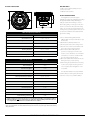
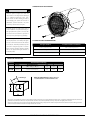
owner’s manual
MX10IB3
Marine Subwoofer
Thank you for choosing a JL Audio Marine Subwoofer.
With proper installation, your new speaker
will deliver years of listening pleasure.
We strongly recommend that you have your subwoofer installed
by your authorized JL Audio dealer. The installation
professionals employed by your dealer have the necessary tools and experience to
properly install this product. If you prefer to perform
your own installation, please read this instruction manual
completely before beginning the process.
PHYSICAL SPECIFICATIONS
A
INCLUDED PARTS
• Six #8 x 1 3/8-inch (35 mm) phillips pan-head
stainless-steel screws
• Six #8 stainless-steel washers
E
C
D
B
Subwoofer Physical Specifications
Nominal Diameter:
10 in. / 250 mm
Overall Diameter (A):
10.75 in. / 273 mm
Mounting Hole Diameter (B):
8.875 in. / 225 mm
Bolt Hole Circle (C):
9.706 in. / 247 mm
Motor Overmold Outer Diameter (D):
5.29 in. / 134 mm
Mounting Depth (E):
5.12 in. / 130 mm
Net Weight:
6.5 lbs. / 2.94 Kg
Driver Displacement:
0.04 ft3 / 1.13 litres
Subwoofer Parameters
MX10IB3
Free Air Resonance (Fs):
41.84 Hz
Electrical “Q” (Qes):
0.806
Mechanical “Q” (Qms):
11.751
Total Speaker “Q” (Qts):
0.754
Equivalent Compliance (Vas):
One-way, Linear Excursion (Xmax)*:
Efficiency (1W/1m)**:
Effective Piston Area (Sd):
DC Resistance (Re):
Nominal Impedance:
Infinite Baffle Use:
Enclosure Use:
Power Handling (continuous):
INSTALLATION PROCEDURE
The diagram above shows the typical
installation procedure into a fiberglass panel using
the supplied hardware. Always follow proper
safety procedures when working on a vessel.
Before cutting, drilling or inserting any screw, check
clearances on both sides of the planned mounting
surface. Also check for any potential obstacles, such
as wiring harnesses, fuel lines, hydraulic lines, etc. Use
eye-protection at all times and a dust mask and
gloves when cutting.
1.29 ft3 / 36.53 litres
0.42 in. / 10.7 mm
1) Choose a flat mounting surface that has
sufficient depth and air space behind it to accept
the subwoofer.
2) Cut a 8.875-inch (225 mm) diameter hole.
3) Run the speaker cable to the mounting location.
4) Place the woofer in the hole and mark the screw
hole locations using a sharp, pointed tool.
5) Remove the woofer and drill a pilot hole
(see chart on next page) in each of the screw
locations. It is also advisable to use a hand-driven
countersink tool on each hole to further inhibit
gel-coat cracking of fiberglass panels.
6) Connect the speaker wires and place the woofer,
with its grille in place, into the opening
7) While holding the speaker firmly in its mounting
location, evenly snug the mounting screws in a
criss-cross pattern, then hand tighten in a crisscross pattern.
Non-standard installations may require different
hardware. Always use marine-grade, stainless-steel
fasteners to ensure a secure, reliable installation.
87.23 dB SPL
50.68 in² / 0.0327 m²
3.957 ohm
4 ohm
Yes
Yes (Sealed Only)
175W
* Xmax specifications are derived via one-way voice coil overhang method with no correction factors applied.
** Efficiency (1W/1m) is not an accurate indicator of a subwoofer’s output capability and should not be used
as a comparison to other subwoofers to determine which one is “louder” !
We recommend the use of this speaker in a bi-amplified system using high-quality satellite speakers and amplifiers.
We do not recommend the use of this subwoofer with a passive crossover (coil), as this type of device will adversely
affect performance.
2
All specifications are subject to change without notice.
JL AUDIO MX10IB3
SUBWOOFER INSTALLATION DIAGRAM
!!
!!
CAUTION
While this speaker is designed to be water and
spray resistant, it is not designed to be submerged
or to withstand high-pressure water spray.
Please exercise care when washing your boat to
avoid damaging your speaker. Do not install on
submersibles, personal watercraft or any other
vessel likely to be under water at any time.
Prolonged exposure to sound pressure levels in
excess of 100dB can cause permanent hearing loss.
This high-performance speaker can exceed this
level. Please exercise restraint in its operation in
order to preserve your ability to enjoy its fidelity.
When installing a subwoofer in your vessel, it is
extremely important to secure it firmly. This applies
#8 SCREW: PILOT HOLE RECOMMENDATIONS
not only to the woofer itself, but also the structure
Fiberglass Thickness
Recommended Pilot Hole Drill Size
0.125 in. (3.18 mm) or less
7/64 in. (2.78 mm) pilot hole
foam core / fiberglass sandwich
7/64 in. (2.78 mm) pilot hole
larger than 0.125 in. (3.18 mm)
1/8 in. (3.18 mm) pilot hole
it is mounted to. If not firmly attached, the speaker
can become a dangerous projectile in a collision.
Please review the mounting information carefully
and use the supplied marine-grade hardware to
mount this product.
ENCLOSURE SPECIFICATIONS
Subwoofer
MX10IB3
Recommended Sealed Design
Volume
(net int.)
External Dimensions
(Width x Height x Depth)
F3
(Hz)
Fc
(Hz)
Qtc
2.0ft
56.6 litres
18 in. x 18 in. x 14.5 in.
457 mm x 457 x 368 mm
42.9
53.66
0.967
3
Sealed Design
NOTE: The MX10IB3 Marine Subwoofer is not
recommended for use in Ported Enclosures.
The enclosure recommendations listed are external dimensions which assume the use of 3/4” (19mm) thick material. If you are using 5/8” (16mm) thick material, subtract 1/4”
(6.5mm) from each dimension. Do not use any material with a thickness of less than 5/8” (16mm) as this may compromise the rigidity of the enclosure.
All enclosure volumes listed are net internal volumes! Box volume displacement, port displacement and brace displacement must be added to obtain the final gross internal
volume. All enclosure dimensions listed have already taken this into account.
JL AUDIO MX10IB3
All specifications are subject to change without notice.
3
RECOMMENDED CONTINUOUS (RMS) POWER RANGE FOR ONE SUBWOOFER DRIVER:
MEDIUM GRAY (MINIMUM):
From a reliability standpoint, this zone
represents a very comfortable operating power
range for each driver. This level of power will not
stress the woofer but will not extract all of its
performance potential, either.
Use of less than the minimum power level
will not damage the woofer, but may result in
unsatisfactory performance.
LIGHT GRAY (OPTIMUM):
This zone represents the best compromise
between long-term reliability, high-output and
low-distortion performance. This power level is
lower than the woofer’s continuous power rating
(as published in its specifications), but you will still
be taking advantage of the woofer’s, low-distortion
performance range without undue risk of failure.
DARK GRAY (MAXIMUM):
Slightly more SPL will be gained by pushing the
power into this zone, but typically not more than
2dB, compared to the light gray zone. The subwoofer
driver is designed to operate safely up to this power
range, but not beyond. Operate with caution.
BLACK (WARRANTY VOID):
We do not recommend operating woofers at
this level of power. In this zone, there is a very
high probability that the driver will fail due to
excessive heat and/or mechanical stress.
Subwoofer drivers operated at these levels of
power are NOT covered under warranty.
When designing systems with our drivers, it is very important to achieve a good power match between the subwoofer amplifier and the subwoofer driver's capabilities. The power levels listed in the above
chart represent continuous (RMS) amplifier power per woofer and assume that the user will regularly make full use of that power without drastically overdriving the amplifier(s). Make sure you factor system
impedance and the total number of subwoofers into your calculations. Adhering to these power recommendations will result in systems that are both reliable and enjoyable.
JL AUDIO LIMITED WARRANTY (USA)
Marine Subwoofer Components
JL AUDIO warrants this speaker to be free of defects in materials and
workmanship for a period of two (2) years from the original date of purchase.
Damage caused by the following is not covered under warranty: accident,
misuse, abuse, product modification or neglect, failure to follow installation
instructions, unauthorized repair attempts, misrepresentations by the seller. This
warranty does not cover incidental or consequential damages and does not cover
the cost of removing or reinstalling the unit(s). Cosmetic damage due to accident
or normal wear and tear is not covered under warranty.
This warranty is not transferable and applies only to the original
purchaser of the product from an authorized JL AUDIO dealer. Warranty is
voided if the factory-applied product serial number is removed or defaced.
Should service be necessary under this warranty for any reason due to
manufacturing defect or malfunction, JL AUDIO will, at its discretion, repair or
replace the defective product with new or remanufactured product at no charge.
Any applicable implied warranties are limited in duration to the period of
the express warranty as provided herein beginning with the date of the original
purchase at retail, and no warranties, whether express or implied, shall apply to this
product thereafter. Some states do not allow limitations on implied warranties,
therefore these exclusions may not apply to you. This warranty gives you specific
legal rights, and you may also have other rights which vary from state to state.
If you need service on your JL AUDIO product:
All warranty returns should be sent to JL AUDIO freight prepaid through an
authorized JL AUDIO dealer and must be accompanied by proof of purchase
(a copy of the original sales receipt.) Direct returns from consumers or nonauthorized dealers will be refused unless specifically authorized by JL AUDIO with
a valid return authorization number. Warranty expiration on products returned
without proof of purchase will be determined from the manufacturing date code.
Coverage may be invalidated as this date is previous to purchase date. Return only
defective components. Non-defective items received will be returned freightcollect. Customer is responsible for shipping charges and insurance in sending the
product to JL AUDIO. Freight damage on returns is not covered under warranty.
Always include proof of purchase (sales receipt).
For Service Information in the U.S.A. please call:
JL Audio customer service: (954) 443-1100 during normal business hours (Eastern Time)
JL Audio, Inc
10369 North Commerce Parkway, Miramar, FL 33025
International Warranties:
Products purchased outside the United States of America are covered only by that country’s distributor and not by JL Audio, Inc.
Printed in U.S.A.
JLMX10IB3-0310-SKU#011016