1
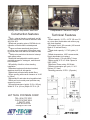
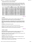
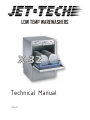
LOW TEMP WAREWASHERS
X-32
Technical Manual
2003 02
Welcome to JET TECH
“creating endless possibilities!”
This manual was created specifically for you, the enduser. We have included information to help troubleshoot
problems and facilitate resolving those problems.
General information pertaining to our range of warewashers will be covered in this section.
Specific information on our current models are
available upon request; model by model.
If you find any discrepancy or can't find certain
information, please contact us. We will be glad to be
of assistance.
JET-TECH SYSTEMS
5771 Ferrier street
Montreal, Quebec H4P 1N3
Tel.: 888-275-4538 (888-ASK-4-JET)
; 514-737-9701
Fax: 514-342-3854
e-mail: [email protected]
2
Warranty
MANUFACTURERS LIMITED WARRANTY
Jet Tech Systems Corporation (Jet Tech) hereby warrants all new warewashers bearing the name “JET TECH” and installed
within the continental United States of America or Canada to be free from defects in material and workmanship, under
normal and regular usage and operation, for a period of one (1) year following the date of original installation, (unless
specified otherwise) but in no event can exceed eighteen (18) months from the date of shipment from the factory.
If a defect in material(s) or workmanship is detected; or found to exist within the stated period above, Jet Tech, at its sole
discretion, shall either repair or replace any original equipment manufacturers part which has proven to fail within the
machine; providing that the equipment has not been altered or tampered with in any manner, has been installed correctly as
per the owners manual, and maintained and operated in complete accordance with this manual.
The labor cost to repair or replace any part proven to be defective, as per above clause(s), shall be covered by Jet Tech
Systems, within the continental United States of America or Canada; provided that: prior authorization for this labor was
approved by Jet-Tech Systems, the service work was performed by an authorized Jet Tech service agency; and that this
agency installed an original and genuine Jet Tech part in the machine. Any repair work performed by a non-authorized
service depot remains the sole responsibility of the user, and Jet Tech Systems will not be held responsible. The installation
of any generic part will not be valid; and therefore voids this warranty. All authorized labor coverage shall be limited to
regular hourly rates only. Any supplemental hourly rates or charges, such as weekends or emergency premiums remain the
responsibility of the user.
Jet Tech Systems Corp. (Jet Tech) hereby states that: warranty travel time shall be limited to, and without exception, a roundtrip total of two (2) hours OR mileage up to a maximum of one hundred (100) miles round-trip. Any charges exceeding those
stated herein must have prior authorization by the factory.
Exceptions to above warranty are: (A) Damages resulting from shipping, handling or abuse. (B) Incorrect installation and/or
connections. (C) Adjustments or calibration of any parts. (D) Faults due to lack of regular maintenance or cleaning of any
internal part(s). (E) Replacement of any wearable items such as: glasswasher curtains, or peristaltic squeeze tubing or
gaskets. (F) Excessive lime, mineral, alkali or hard water conditions (In excess of 6 grain) and (G) Poor results due to: use of
an incorrect type of detergent (for non-commercial type applications), and excessive or inadequate water temperature(s) or
pressure conditions or incorrect use. (H) Labour and mileage coverage does not apply upon condition of sale.
JET TECH SYSTEMS CORPORATION STATES THAT THERE ARE NO OTHER WARRANTIES, EXPRESSED OR
IMPLIED, THAT ARE NOT SET FORTH HEREIN, JET TECH SYSTEMS CORPORATION SHALL ASSUME NO
OTHER RESPONSIBILITY, EITHER DIRECT OR NON-DIRECT, OR BE LIABLE FOR ANY OTHER OR
ADDITIONAL LOSS OR DAMAGE WHETHER BEING DIRECT OR CONSEQUENTIAL, AS A RESULT OF ITS
EQUIPMENT.
Warranty:
One year parts & labor (Continental USA and Canada).
Exceptions: Model “F14” - 90 days labor & One year parts.
The manufacturer reserves the rights to alter design and specifications without notice.
3
Independent Chemical Pumps
Sanitary inner “deep-drawn” wash tank
Construction features
Technical Features
mBody , external housing, wash tank, and all
cm)
mRack capacity: 19.75" x 19.75" (50 cm x 50
cm) (one open combination rack and on peg
dish rack supplied)
mComplete cycle: 160 seconds (145 second
Wash & 15 second Rinse)
mWash tank capacity; 3.17 US gallon (12
liters)
mWash temperature; 140F recommended,
Supply dependant (no heaters)
mPower supply: 110 volts 60Hz 7 Amps
mMotor pump; 0.75 H.P. With Clipson at
320F (160C)
mMaximum Power rating; 550 Watts
mWater consumption per cycle; 1.5 U.S.
Gallons (5.7 liters)
mworking pressure; 25 P.S.I. (Dynamic)
chassis components in brushed stainless steel
AISI 304 18/8
mReduced operating noise of 58 DbA due to
utilization of double-wall insulated panels
mUpper and lower wash and rinse jets on
revolving arms constructed of fiberglass; easy
to remove and clean without the need for tools
mSafety micro-switch on the door to interrupt
wash pump action
mIndividual and adjustable variable speed
peristaltic pumps for: detergent, sanitizer and
rinse-additive.
mPossibility of built-in or free standing
installation
mStandard equipment includes insulated,
stainless steel top & side panels
mWash tank protected with double filters.
mDoor opening with overall clearance of 14.25
in (36cm)
mAutomatic fill and water level regulation tank
mSlide-out front control panel provides easy
access for service.
mOverall dimensions: height: 33.5 in. (85 cm)
Width 23.75 in. (60 cm) Depth: 23.75 in. (60
JET TECH SYSTEMS CORP.
TEL: (514) 737 9701
FAX (514) 342 3854
1 888 275 4538
WWW.JET-TECH.COM
[email protected]
4
DRAIN
The X‐32 is equipped with an automatic drain pump that will pump the drain
water to a maximum height of 36" (0.9 meter). A 1" ID flexible drain hose is
included to facilitate maintenance and servicing of the machine. It is important
not to reduce the size of this hose. The drain should have a loop at the back of
the dishwasher as per illustration below. The loop should be 36 inches (36”)
above the floor and drop down into a drain pipe with an air gap. These
instructions must be followed for proper dishwasher operation. It is normal for
some water to remain in the wash tank after draining.
WATER INLET
A 3/4” NPT coupling is required with a maximum of 20 p.s.i. dynamic pressure,
and a minimum of 18 p.s.i. . A water pressure regulator is required. The water
pressure should be 20 p.s.i. Incoming water temperature must be 140º F ( 60º
C). An easily accessible shut‐off valve is recommended ‐‐‐ making installation,
service and repairs easier.
Flexible hoses must be used to make installation, servicing and maintenance
easier.
Make sure that the water is free from calcium and hard water deposits. Water
with a mineral contain of 6 grains or higher must have an on‐line water filtering
system or some other type of water softening system. Build‐up of calcium and
lime deposits in the washer may occur and servicing will be required on
a more frequent basis which will not be covered by the warranty.
ELECTRICAL
Unit must be connected with a 110 volts 60Hz line. The terminal block will
receive L1, N and Ground wire. Unit must be well grounded. Breaker rating
should be 15 amps.
Getting Started
Immediately upon receipt of your new X-32 dishwasher, inspect the dishwasher for any obvious
signs of damage. If you do find any traces of damage, contact the transport company that
brought the dishwasher to your place at once.
A damage claim must be made immediately with the carrier.
Please assure that the following items are included with your X-32 dishwasher.
! (1) 20 x 20 open rack
! (1) 20 x 20 peg rack for dishes
!4 adjusting feet
!1 operators manual
5
Chemical hook-up
This unit is equipped with three (3) chemical pumps. Each will
inject a different liquid product at a specific time during the
wash cycle. The chemical pumps have sufficient length of
tubing hose that can be inserted in gallon containers near the
dishwasher.
The chemical pumps have colored tubing for ease of
identification. The colors are as follow;
Red for Detergent
Clear for Sanitizer
Blue for Rinse-additive
To prime the pumps; you must complete two full wash cycles.
You can adjust the amount injected by turning the white screw on the
chemical pump.
Installation Check List
- Is the dishwasher connected electrically?
- Is the breaker turned on?
- Is there water connected to the dishwasher?
- Is the water valve opened?
- Are the chemicals properly set?
Starting the dishwasher the first time
When starting the dishwasher for the first time, you will notice that the only chemical that gets
drawn in is the detergent. The other chemicals will get drawn only during the wash cycle.
For more information go to Operation section.
7
Operation
1.
When you start the power (GREEN PUSH-BUTTON) TL the machine automatically
starts to fill the water until the correct water level is reached. During the fill,
the solenoid valve EC and the detergent dosing pump MPD are operating.
2.
By pushing the (BLACK ROUND) push-button TC, the programmed washing cycle starts. The
length of the times are shown in the schematic electrical diagram:
3.
2.1
From 0" to 30" the machine is washing and only the wash pump is operating.
2.2
From 30" to 50" while the wash pump is working; also the sanitizer dosing pump MPSA
is operating to fill the dishwasher with chemical sanitizer.
2.3
From 50" to 60" the machine is washing and only the wash pump MPL is operating.
The wash pump stops to operate when the timer has reached 60" of time.
2.4
From 60" to 63" is the dripping time; and in this phase only the timer still works.
2.5
From 63" to 83" the solenoid valve ER and the rinse chemical pump MPB are
operating. MPB is delivering the right quantity of rinse aid product. The quantity can be
pre-determined with the adjustment of the pump. At the same time , 63" to 83", the drain
pump MPS is operating. At this time the cycle has ended and the drain pump only is
operating from 83" to 99" ; and automatically the dishwasher is ready to start again.
The black (SQUARE) push-button has a double function:
.
First function: to give the possibility to make a pre-wash or a continuous wash for as
long as you want. - in pushing the black button the wash pump MPL works. To stop
the wash pump you must have the black push-button in OFF position.
.
Second function: is for de-lime. The operator must put the de-liming chemical product in
the water in the wash tank of X-32 and then push the black button. When the de-lime
push-button is in the ON position the wash pump MPL is working: FOR NORMAL
WASHING CYCLE THE PUSH-BUTTON FOR DE-LIME MUST BE IN THE OFF
POSITION. If during the wash cycle the de-lime button is pushed in, the wash cycle will
stop and will only start again when the button is depressed, this from the position
reached at the moment that the de-lime button has been pushed.
4.
The white (SQUARE) push-button is for the total drain of the tank when the operator has
finished the washing operations
1 - Drain Button
2 - Extended / delime button
3 - Power switch
4 - Indicator light (power)
5 - Thermometer gauge
6 - Wash cycle, Start button
7 - Indicator light (wash cycle)
8
Electrical Schematics
DPS - Drain pump By-pass switch
MPS - Drain Pump
TL - Main Power switch
PS1, PS2 - Pressure switches
ER - Rinse solenoid valve
EC - Fill solenoid valve
MPD - Detergent pump
MPB - Rinse additive pump
MPSA - Sanitizer pump
MP - Door switch
TLS - Deliming option switch
CRP - Contact from relay
MT - Timer motor
M1, M2, M3, M4, M5 - Timer
contact
LC - Light, Timer cycle
MPL - Wash pump
BR - Relay coil
TC - Start switch
CR - Contactor relay swicth
LL - Light, Main power
BRP - Relay coil
9