1
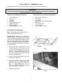
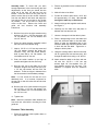
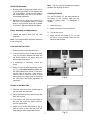
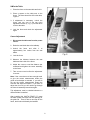
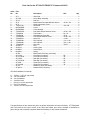
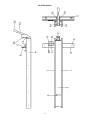
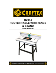
OWNER’S MANUAL
XACTA FENCE II™ Commercial 30/50
JET EQUIPMENT & TOOLS, INC.
A WMH Company
www.jettools.com
P.O. BOX 1349
Auburn, WA 98071-1349
e-mail [email protected]
253-351-6000
Fax 253-939-8001
M-708950X 3/01
Important Information
2-YEAR
JET offers a two-year limited
warranty on this product
LIMITED WARRANTY
REPLACEMENT PARTS
Replacement parts for this tool are available directly form JET Equipment & Tools.
To place an order, call 1-800-274-6848. Please have the following information ready:
1. Visa, MasterCard, or Discover Card number
2. Expiration date
3. Part number listed within this manual
4. Shipping address other than a Post Office box.
REPLACEMENT PART WARRANTY
JET Equipment & Tools makes every effort to assure that parts meet high quality and durability
standards and warrants to the original retail consumer/purchaser of our parts that each such part(s) to be
free from defects in materials and workmanship for a period of thirty (30) days from the date of purchase.
PROOF OF PURCHASE
Please retain your dated sales receipt as proof of purchase to validate the warranty period.
LIMITED TOOL AND EQUIPMENT WARRANTY
JET makes every effort to assure that its products meet high quality and durability standards and warrants to the
original retail consumer/purchaser of our products that each product be free from defects in materials and
workmanship as follows: 2 YEAR LIMITED WARRANTY ON THIS JET PRODUCT. Warranty does not apply to
defects due directly or indirectly to misuse, abuse, negligence or accidents, repairs or alterations outside our
facilities or to a lack of maintenance. JET LIMITS ALL IMPLIED WARRANTIES TO THE PERIOD SPECIFIED
ABOVE FROM THE DATE THE PRODUCT WAS PURCHASED AT RETAIL. EXCEPT AS STATED HEREIN, ANY
IMPLIED WARRANTIES OR MECHANTABILITY AND FITNESS ARE EXCLUDED. SOME STATES DO NOT
ALLOW LIMITATIONS ON HOW LONG THE IMPLIED WARRANTY LASTS, SO THE ABOVE LIMITATION MAY
NOT APPLY TO YOU. JET SHALL IN NO EVENT BE LIABLE FOR DEATH, INJURIES TO PERSONS OR
PROPERY OR FOR INCIDENTAL, CONTINGENT, SPECIAL OR CONSEQUENTIAL DAMAGES ARISING FROM
THE USE OF OUR PRODUCTS. SOME STATES DO NOT ALLOW THE EXCLUSION OR LIMITATION OF
INCIDENTAL OR CONSEQUENTIAL DAMAGES, SO THE ABOVE LIMITATION OR EXCLUSION MAY NOT
APPLY TO YOU. To take advantage of this warranty, the product or part must be returned for examination,
postage prepaid, to an authorized service station designated by our Auburn office. Proof of purchase date and an
explanation of the complaint must accompany the merchandise. If our inspection discloses a defect, JET will either
repair or replace the product or refund the purchase price, if we cannot readily and quickly provide a repair or
replacement, if you are willing to accept such refund. JET will return repaired product or replacement at JET’s
expense, but if it is determined there is no defect, or that the defect resulted from causes not within the scope of
JET’s warranty, then the user must bear the cost of storing and returning the product. This warranty gives you
specific legal rights, and you have other rights, which vary, from state to state.
JET Equipment & Tools • P.O. Box 1349, Auburn, WA 98071-1349 • (253) 351-6000
2
XACTA FENCE II™ COMMERCIAL 30/50
Note: This manual also runs through the steps of installing the rails, and extension table.
WARNING
Disconnect the table saw from the power source before attempting any assembly or adjustment!
Failure to comply may cause serious injury!
Contents of the Shipping Containers
Tools Required for Assembly & Adjustment
1
1
1
1
3
1
1
1
1
1
1
1
1
1
2
1
XACTA FENCE II™
Front Rail
Rear Rail
Guide Rail
Black Plastic End Caps
Hardware Package
Owner’s Manual
Warranty Registration Card
Front and Rear Rail Assembly
Note: The hardware should be packed in the
guide rail along with the end caps.
Assembly Note: Depending on the size of the
extension table you are using, you may need to
remove the right side extension wing. You need
to have four bolts attaching the extension table
to the front and rear rails. Use a JET extension
table or one designed and built by the operator.
If you are planning to build a table, see Figure 1
for the dimensions.
1. Bolt the front rail to the table (not to the
extension wing at this time) with two 1/4”-20
x 1-1/4” hex cap screws, four 1/4” flat
washers, two 1/4” lock washers and two 1/4”
hex nuts. Tighten just enough to hold the
rail next to the table but keep loose enough
to allow height adjustment.
2. Setting the combination square at 9/16” will
clear the miter gauge slot.
3. Place the combination square on the table
and adjust the rail to approximately 9/16”
below the table surface, see Figure 2.
Note: It is more important to have the
front rail parallel to the table top than
exactly 9/16” below the table top.
4. Tighten hex cap screws.
3
#3 Cross Point Screwdriver
7/16” Wrench
1/2" Wrench
Combination Square & Straight Edge
Electric Drill
1/4”, 3/16” Drill Bits
4”-6” C-Clamps
1/4”, 3/16” Allen Wrenches
2. Place a leg bracket into the outboard end of
the table.
Assembly Note: To insure that you have
enough adjustment in the cursor during the final
adjustments, at this time you should bolt the
guide rail to the front rail with two hex cap
screws. Place the fence on the guide rail so
that the cursor lines up at four inches. Measure
from the saw blade to the fence and adjust the
front rail so that you are as close to four inches
as possible. You do not have to adjust the
cursor at this time. Remove the fence and
guide rail and continue with assembly
instructions.
3. Mark all holes to be drilled.
4. Pre-drill all marked holes with a 3/16” drill
bit approximately 1/2” deep. Do not drill
through the table top or table frame!
5. Attach both legs with supplied wood screws,
see Figure 3.
6. Carefully turn the table over and place in
between the front and rear rail.
5. Bolt the front rail to the right extension wing
with one 1/4”-20 x 1-1/4” hex cap screw, two
1/4” flat washer, one 1/4” lock washer, and
one 1/4” hex nut.
7. Use two c-clamps to hold the table in place.
8. Place a straight edge on the saw table and
level the extension table to the saw table.
Raise or lower the adjustable feet on the
extension table legs until the extension table
is level with the saw table. Tighten the cclamps to hold in place.
6. Place the switch bracket assembly behind
the hole in the left extension wing.
7. Insert a 1/4”-20 x 1-1/4” hex cap screw and
1/4" flat washer through the guide rail,
extension wing, and the switch bracket.
Hold in place with a 1/4" flat washer, 1/4"
lock washer and 1/4" hex nut.
9. Using the existing holes in the front and rear
rail as a guide (two front and two rear), drill
through the table frame using a 1/4” drill bit.
8. Push the switch bracket up as high as
possible and tighten the hex nut firmly.
10. Attach extension table to the front and rear
rail with four 1/4”-20 x 1-1/4” hex cap
screws, eight 1/4” flat washers, four 1/4”
lock washers, and four 1/4” hex nuts. This
hardware is supplied with the extension
table.
9. Bolt the rear rail to the table (not to the
extension wings at this time) with two 5/16”
x 1/2” hex cap screws, and two 5/16” flat
washers. These are larger in diameter than
the other screws in the hardware package.
Note: It is not critical for the rear rail to be
absolutely level. It is, however, important for
the rear rail to clear the miter slots and be level
as possible.
10. Bolt the rear rail to each extension wing with
two 1/4”-20 x 1-1/4” hex cap screws, four
1/4” flat washers, two 1/4” lock washers, and
two 1/4” hex nuts.
11. Tighten nuts.
Note: Mount the extension table between the
front and rear rails before mounting the front
guide rail.
Extension Table Assembly
1. Place the extension table upside down on
top of the table saw.
4
Guide Rail Assembly
Note: You may need to re-adjust the clamping
pressure after aligning the fence.
1. Bolt the guide rail to the front rail with 1/4-20
x 3/4” hex cap screws 1/4" flat washers and
1/4" lock washers. Center the bolt heads in
the slotted holes of the rail so you will have
some lateral adjustment.
Clamping Pressure
The XACTA FENCE II™ has been adjusted at
the factory to lock securely when the lock
handle is pushed down.
If adjustment is
needed:
2. Measure from the front of the guide rail to
the front of the tablesaw table in a couple
spots to verify that the guide rail is parallel
to the table. Adjust as needed and tighten.
1. Unlock the fence.
2. Remove the fence from the guide rail.
Fence Assembly and Adjustments
3. Turn the fence over.
1. Thread the handle knob into the cam
assembly.
4. Adjust the two set screws (A, Fig. 5) until
the fence is held securely when the lock
handle is pushed down.
Note: Fence adjustments should be performed
in the order given.
Level with the Saw Table
1. Place the fence on the table and lock it.
2. View the fence from the left side of the saw.
Look for the space between the table and
the fence bottom to be equal along the
entire length of the fence.
3. If adjustment is necessary, unlock the
fence.
4. Raise or lower two nylon adjustment screws
(A, Fig. 4) the same number of turns until
the space between the bottom of the fence
and the table is the same. Care must be
taken to raise or lower the fence on each
side equally or the fence may not be 90° to
the table after the height adjustment is
performed.
Parallel to the Miter Slot
1. Place the fence next to the outside edge of
the right miter slot and lock it.
2. The fence should be even with the miter slot
from front to back.
3. If the fence is not even along the length of
the miter slot, unlock the fence, remove it
and turn upside down.
4. Adjust one of the two set screws (A, Fig. 5)
until the fence is even with the miter slot
edge along its entire length when locked.
5
90°° to the Table
1. Place the fence on the saw table and lock it.
2. Place a square on the table next to the
fence. The fence should be 90° to the table,
Figure 6.
3. If adjustment is necessary, unlock the
fence, and turn one of the two nylon
adjustment screws (A, Fig. 7) until the fence
is 90° to the table.
4. Lock the fence and check the adjustment
again.
Cursor Adjustment
1. Disconnect the table saw from the power
source.
2. Raise the saw blade above the tabletop.
3. Unlock the fence and slide it to
approximately four inches from the saw
blade.
4. Lock the fence.
5. Measure the distance between the saw
blade and the inside of the fence.
6. Adjust the cursor to read the distance just
measured and tighten the cursor assembly
to the fence.
7. Take a test cut and confirm the adjustment
is correct.
Note: If the cursor does not have enough travel
to give the correct measurement loosen the
guide rail and adjust as needed. If you still do
not get the correct measurement loosen the
front rail and adjust as needed. If you have to
adjust the front rail you will need to go through
the front rail assembly instructions again.
This adjustment must be checked whenever a
different blade is installed.
After installing the XACTA FENCE II™ press
the black plastic end caps into the openings of
the guide rail. There is also an end cap for the
fence, but this should already be installed.
6
Parts List for the JET XACTA FENCE II™Commercial 30/50
Index Part
No.
No.
Description
Size
Qty.
1..........XF-1................................. Side Plate...................................................... ................................... 2
2..........XF2-2W ........................... Fence Body Assembly ................................... ................................... 1
3..........XF2-3............................... Pad Set ......................................................... ................................... 1
4..........XF-4................................. Brass Plated Pan Head Machine Screw......... 10-32 x 3/4 ............... 12
5..........XF-5................................. Nylon Adjustment Screw................................ ................................... 2
8..........TS-0271031 ..................... Set Screw...................................................... 3/8 x 3/8 ..................... 2
9..........800708950D..................... Cursor ........................................................... ................................... 1
9A........800708950C..................... Cursor Bracket .............................................. ................................... 1
10 ........TS-081D022..................... Pan Head Phillips Machine Screw ................. 10-32 x 3/8 ................. 2
11 ........TS-069204 ....................... Flat Washer................................................... No. 10......................... 4
12 ........TS-056008 ....................... Hex Machine Screw Nut ................................ 10-32 .......................... 2
............TS-081D021..................... Flat Phillips Machine Screw........................... 10-32 x 3/8 ................. 2
13 ........TS-0640071 ..................... Nyloc Nut ...................................................... 1/4-20 ......................... 1
14 ........TS-0050081 ..................... Hex Cap Bolt ................................................. 1/4 x 1-3/4 .................. 1
15 ........TS-0060081 ..................... Hex Cap Bolt ................................................. 3/8 x 1-3/4 .................. 1
16 ........TS-0640091 ..................... Nyoc Nut ....................................................... 3/8-16 ......................... 1
18 ........3215301........................... Foot............................................................... ................................... 1
19 ........3076232........................... Locking Cam ................................................. ................................... 1
20 ........6430055........................... Knob w/Stud .................................................. ................................... 1
21 ........6813092........................... Spring............................................................ ................................... 1
............XF-EC.............................. Black Plastic End Cap (not shown) ................ ................................... 3
............XF2-21W ......................... Front Rail (not shown) ................................... 50”.............................. 1
............XF2-21-30W .................... Front Rail (not shown) ................................... 30”.............................. 1
............XF2-22W ......................... Rear Rail (not shown) .................................... 50”.............................. 1
............XF2-22-30W .................... Rear Rail (not shown) .................................... 30”.............................. 1
............XF-23W ........................... Guide Rail (not shown) .................................. 50”.............................. 1
............XF-23-30W ...................... Guide Rail (not shown) .................................. 30”.............................. 1
............XF-24............................... Measuring Tape (not shown).......................... ................................... 1
............XF-HK-N .......................... Hardware Kit (not shown)............................... ................................... 1
XF-HK-N Hardware Kit contents:
6..... 1/4-20 x 1-1/4” hex cap screws
12 ... 1/4” lock washers
22 ... 1/4” flat washers
6..... 1/4-20 hex nuts
1
5/16-18 x 1/2 hex cap screws
2..... 5/16” Flat Washers
6..... 1/4-20 x 3/4” hex cap screws
The specifications in this manual are given as general information and are not binding. JET Equipment
and Tools reserves the right to effect, at any time and without prior notice, changes or alterations to
parts, fittings, and accessory equipment deemed necessary for any reason whatsoever.
7
Parts Breakdown
8