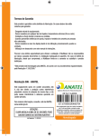
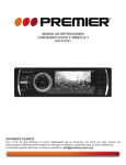
1
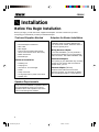
®
How to Install the CR560X AM/FM
Stereo Radio/Cassette Tape Player
Install
half-sleeve
(page 5)
1
4
Final
Installation
(page 10)
2
AS/P
S
BAN
D
VOL
CD
+
SEL
VOL
-
LOUD
MUT
E
MON
O
1
2
SCAN
DISP
3
4
5
STER
Install wiring
(pages 6 and 7)
Installation
Contents
Installation ................................... 2
Before You Begin Installation ........ 2
Tools and Supplies Needed ........... 2
Speaker Requirements .................. 2
Adapters for Easier
Installation ..................................... 2
• Connections ............................... 3
• Crimp Connections .................... 3
• Upgrading your System ............. 3
Disconnect Battery ........................ 4
Remove Old Radio ........................ 4
Install Half-sleeve .......................... 5
EO
6
FM
Wiring ............................................. 5
1
CH
REL
BAS
®
CR56
0X
3
Connect and
test radio
(pages 8 and 9)
Welcome!
What you're holding in your hands is no ordinary owner's
manual. We've tried to make the instructions in this book
clear and easy to follow.
For your Jensen stereo to work right, it must be installed
correctly. This manual will show you how to install your new
stereo like a pro. It's a good idea to read all of these
instructions before you begin the installation. Most
installations are straightforward and can be handled by a
do-it-yourselfer with the right tools, patience, and the ability
to follow instructions. But, do-it-yourself installation isn't for
everyone. If you still don't feel confident after reading this
book, consider turning the installation job over to someone
better suited to it.
Warranty Service
If your Jensen stereo should ever require service, you will
need to have the original dated receipt. If you ever need to
return the unit for any reason, always include the receipt
with the product.
• Fuse Adapters ........................... 5
• Cars with a Single
Speaker Wire ............................. 5
Wiring with a Wiring Adapter ......... 6
Connect Wires ............................... 6
Install Wiring Inside the Car .......... 6
Wiring Diagram–Advanced
Installation ..................................... 7
Testing .......................................... 8
Reconnect Battery ......................... 8
Test Power Wiring .......................... 8
Test Antenna Connection .............. 8
Test Memory Wiring ....................... 8
Set the Clock ................................. 8
Test Speaker Connections ............ 9
Final Installation ........................... 10
Final Installation–ISO-DIN ........... 10
Troubleshooting ....................... 11
Removing Radio from Dash ........ 11
• Securing Wires ........................ 11
Specifications
and Warranty ........................ 12
Technical Assistance
For technical assistance with the installation of the
CR560X, call 1-800-323-0221.
5588 CR560X_EIN.p65
1
2/29/00, 10:46 PM
®
CR560X
Installation
Before You Begin Installation
Before you begin, you will need tools, supplies and adapters. It is best to make sure you have
everything you need before you take your dashboard apart.
Tools and Supplies Needed
Basic Installation:
•
•
•
•
Flat and Phillips screwdrivers
Wire cutter
Wire stripper
Tools to remove existing radio (screwdriver, socket wrench set or other tools)
• Radio removal tool
• Electrical tape
Advanced Installation:
•
•
•
•
•
•
•
Soldering iron
Crimping tool
Volt meter or 12 volt test light
Solder
Crimp connectors
14-18 gauge wire for power connections
Speaker wire
Adapters for Easier Installation
Electrical and dashboard adapters make
installation easier. Purchase adapters from
your local Jensen retailer, electronics store or
car stereo specialty store.
Wiring Harness Adapter
For a basic installation, you can purchase a
wiring harness adapter for your car's existing
radio connectors. This makes installation easy.
Dashboard Adapters
The opening in your dashboard may not match
the size of your Jensen radio. Purchase an
adapter kit for your car.
Antenna Adapter (GM cars)
1990 and newer GM cars have a small
antenna connector. You will need an adapter
when installing this radio in a newer GM car.
Speaker Requirements
Only connect the CR560X to speakers rated in
the load impedance range of 4 to 8 ohms.
Speakers with a load impedance less than 4
ohms could damage the CR560X.
2
5588 CR560X_EIN.p65
2
2/29/00, 10:46 PM
®
CR560X
Professional Tip
Professional Tip
Connections
Crimp Connections
Good wire connections are very important for
best sound and long-term reliability. Here are
two methods:
Purchase crimp connectors and crimping
tool. Connectors are color coded. This
Jensen radio uses RED connectors (18-20
gauge wire).
1. Strip 1/4 inch (6mm) of insulation from
both wires.
2. Insert into connector.
3. Crimp tightly.
You can make permanent splices (using
butt connectors) or select connectors that
can be removed and reinstalled.
Splice
1. Strip 1/2 inch (12 mm) of insulation from
both wires.
2. Wrap wires together
3. Fold wires over
4. Stretch electrical tape tightly over splice.
Splice
1
Strip Wire
1/2" (12mm)
1
Solder
Rosin core
solder
2
Heat
wires
not
solder
3
2
3
Strip Wire
1/4' (6mm)
Soldering
iron
4
Solder
Solder is the best way to connect wires, but it
takes skill and practice. Splice the wires (as
shown above). Before taping, heat the wires
(not the solder). When the wires are hot
enough, touch the solder to the splice. The
solder will flow over the wires. Stretch
electrical tape tightly over splice.
Important:
Be very careful when soldering wires in your
car. Cover nearby carpeting and seats to
prevent damage from hot solder.
Professional Tip
Upgrading Your System
International Jensen makes a wide range of
car stereo products that will make your car
system sound better, great or INCREDIBLE!
Better Sound
Install a Jensen tape deck or CD player like
you’re doing now. High power units can
make your existing speakers sound better
and play louder.
Great Sound
Replace your existing speakers with Jensen
speakers. Many of our speakers will fit into
your car without cutting or drilling. You can
also add an amplified graphic equalizer to
tailor the sound to your liking.
INCREDIBLE Sound
Jensen offers a full line of amplifiers, highpower speakers and subwoofers that can
turn your car into audio dynamite. You can
go loud, louder and loudest by selecting
Jensen components from your retailer.
3
5588 CR560X_EIN.p65
3
2/29/00, 10:46 PM
®
CR560X
Disconnect Battery
Before you begin, always
disconnect the battery
negative terminal.
–
+
Remove Old Radio
Your original car radio is installed in one of four ways, depending on the car.
Bracket Mounted
Removal Tool
1. Remove dashboard faceplate
2. Unscrew brackets
3. Disconnect wiring harness and
remove radio
Some cars use a special removal tool
to release the radio.
1. Insert the tool(s)
2. Pull out the radio
3. Disconnect wiring harness and remove radio
EJ
®
4x25W
JensenAuto Revers
Plus
Tuner e
MUTE
SEEK
BBE
LD
LOC
AM
PM
A•PS
EJ
®
4x25W
JensenAuto Revers
Plus
Tuner e
MUTE
EN
OP
SEEK
BBE
LD
LOC
AM
PM
A•PS
CH
EN
OP
Replacing an Aftermarket Radio
ISO-DIN
Use a screwdriver to bend tabs completely out
of the way. Pull sleeve from dashboard. The
sleeve should fit tightly and may be damaged
unless you remove it carefully.
1. Remove trim to expose DIN chassis.
2. Remove the ISO-DIN frame from the
dashboard.
3. Unscrew screws from the sides.
4. Disconnect wiring harness and remove
radio.
1
Bend
Tabs
Flat
2
3
2
Pull Sleeve Out
Caution: Edges are
sharp. Use a rag
or wear a glove.
1
COMPACT
EJECT
DIGITAL
AUDIO
RGCD
400
8 X OVERS
AMPLIN
G..
CD
.4X
15 WATTS
PWR
BASS
BAND
MO/ST
DISP
CD
LO/DX
INT
VOL
SEL
VOL
RPT
RDM
4
5588 CR560X_EIN.p65
4
2/29/00, 10:46 PM
®
CR560X
Install Half-sleeve
Not needed for ISO-DIN (Japanese vehicle) installation.
3
Support Strap
(supplied)
Half-sleeve
(supplied)
1
Adapter
(optional)
1. Install adapter if necessary. Install halfsleeve into adapter from front of dash. It
will be a tight fit.
2
2. Bend over tabs where possible to secure
half-sleeve to adapter or inside of dash.
3. Install strap to strut under dash. Secure
strap to an existing screw.
Wiring
Important
If wiring connections are made wrong, the
unit will not operate properly and it could be
damaged. Follow the installation instructions
carefully, or have the installation handled by
an experienced technician.
Professional Tip
Fuse Adapters
No convenient power wire? Install a fuse
adapter having a spade connector.
Fuse
Fuse
Adaptor
Crimp on a matching connector and attach:
• Yellow wire–Fuse marked MAIN, BAT
or PWR
• Red wire–Fuse marked ACCY
(accessory), or RADIO
5
5588 CR560X_EIN.p65
5
2/29/00, 10:46 PM
®
CR560X
Wiring with a Wiring Adapter
This is the easiest wiring method, because it replaces your existing radio. You will have to buy a wire
harness adapter from your dealer, a car stereo installation shop or electronics store. If you use a wiring
adapter, you can connect all wires to the radio before you even start to take your old radio out.
Connect Wires
Install Wiring Inside the Car
Splice, crimp or solder the wires from the
Jensen connector to the wiring adapter. Match
the wires according to the chart (below) and
the wiring adapter instructions.
Splices
You can make all
these connections
without even being
in the car.
1. Connect wiring adapter to the car's
existing wiring harness.
2. Connect antenna extender cable to car
antenna lead.
3. Slide radio part way into half-sleeve.
1 Car Wiring
Harness
3
Antenna
Extender
Cable
2
Car
Antenna
Lead
Wiring Adapter
(attach to car wiring harness)
Wiring Color Codes
Function
LF– Speaker
LF+ Speaker
LR– Speaker
LR+ Speaker
RF– Speaker
RF+ Speaker
RR– Speaker
RR+ Speaker
Power Antenna
Ground
Ignition
Battery
Go to Testing on page 8.
Color
white/black
white
green/black
green
gray/black
gray
violet/black
violet
dark blue
black
red
yellow
6
5588 CR560X_EIN.p65
6
2/29/00, 10:46 PM
®
CR560X
Wiring Diagram–Advanced Installation
If you are installing new speakers or amplifiers or replacing an aftermarket installation, use this diagram.
Back of Radio
Antenna
Jack
RCA-to-RCA cables
Amplifier wiring
(not supplied)
(See amplifier instructions)
Red
AMP
White
Power Antenna
Connect to power antenna or amplifier. If not used, tape bare end of
wire.
Dark Blue
Turn on for amps
AMP
Filter
Box
Ground
Connect to ground terminal or clean,
unpainted metal part of chassis.
Black
+
LF
LF—
white/black
Yellow
In-line
Fuse
(.5 amp)
Red
RF—
gray/black
LR—
green/black
RR—
violet/black
green
LR+
violet
RR+
Accessory
Connect to existing radio wire or
radio fuse.
The radio will not work if this wire
is not connected.
RF
Fuses
gray
RF+
white
LF+
LR
In-line
Fuse
(5 amp)
Memory
Connect to battery or 12 volt power
– source that is always live.
The radio will not store time or
station presets if this wire is not
connected.
RR
When replacing a fuse, make sure new fuse
is correct type and amperage. Using an
incorrect fuse could damage radio. The
CR560X uses two fuses with in-line
fuse holders as part of rear wiring harness:
• 5 amp fast blow AGC (yellow wire).
• .5 amp fast blow AGC (red wire).
Go to Testing on page 8.
7
5588 CR560X_EIN.p65
7
2/29/00, 10:46 PM
®
CR560X
✓ Testing
Before you finish the installation, you should do the following tests to make sure the wiring is correct
and everything is operating properly.
Reconnect Battery
When wiring is complete,
reconnect the battery
negative terminal.
Test Memory Wiring
1
—
1. With the radio playing, hold
button 1 for two seconds.
CH 1 will appear on the
display. You just stored the
current station in memory.
2. Turn the key off, then turn
the key on again.
3. The radio should resume
playing at the same station
and volume. If not, make
sure the yellow wire is
connected properly.
1
+
2
Test Power Wiring
1. Turn ignition switch on. Press the
(Power) button to turn the radio on. The
display should light and show the radio
display. If not, check the electrical
connection at the yellow and red wires.
2. If equipped, the power antenna should
also operate. If not, check electrical
connections to the dark blue wire.
Set the Clock
Press DISP button to display the clock.
DISP
1
Test Antenna Connection
1
or
2
VOL +
1. Hold a tuning button
for more than two
seconds. The radio
should tune to a
nearby station. If
not, check antenna
connection.
2. Press + to increase
volume until you
can hear the radio
playing.
1. Press DISP button for
three seconds until
display flashes.
2. Press
to change
minutes,
to change
hours.
2
M
H
8
5588 CR560X_EIN.p65
8
2/29/00, 10:46 PM
®
CR560X
Test Speaker Connections
These tests make sure the speakers are connected right. If speakers don’t play at all, both wires
may not be connected. If the wrong speaker plays (you hear front speakers when you expect rear
speakers) make sure you connected the wires right.
Balance
1
2
3
SEL
SEL
SEL
SEL
VOL +
SEL
SEL
SEL
SEL
4
VOL –
Fader
1. Press SEL four times.
2. Hold the + button until
the display shows
BA.r 10.
Only the right speakers
should be playing.
If not, check the wiring.
Make sure you connected
the wires just like the chart
on page 6.
3. Press SEL four times
again.
4. Hold the – button until
the display shows
BA.L 10.
Only the left speakers
should be playing.
If not, check the wiring.
Make sure you connected
the wires just like the chart
on page 6.
5
6
7
8
SEL
SEL
SEL
SEL
SEL
VOL +
SEL
SEL
SEL
SEL
SEL
VOL –
5. Press SEL five times.
6. Hold the + button until
the display shows
FA.F 10.
Only the front speakers
should be playing.
If not, check the wiring.
Make sure you connected
the wires just like the chart
on page 6.
7. Press SEL five times
again.
8. Hold the – button until
the display shows
FA.r 10.
Only the rear speakers
should be playing.
If not, check the wiring.
Make sure you connected
the wires just like the chart
on page 6.
Once everything is operating correctly, perform Final Installation on page 10.
9
5588 CR560X_EIN.p65
9
2/29/00, 10:46 PM
®
CR560X
Final Installation
1.
2.
3.
4.
Slide radio chassis into half-sleeve
Secure to strap using nut
Install faceplate by fitting left edge into position then pushing right edge closed.
Reinstall any items you removed from the dashboard.
2
Nut
(supplied)
1
3
AS/P
S
BAN
D
VOL
CD
+
LOUD
MUT
E
SEL
VOL
MON
O
-
1
2
SCAN
3
DISP
4
STER
5
EO
6
FM
1
CH
REL
BAS
®
CR56
0X
Final Installation–ISO-DIN
1.
2.
3.
4.
5.
Remove trim ring from front of radio. Trim ring is not needed for this type of installation.
Mount factory brackets on new radio using existing screws from old radio.
Slide radio and frame into dash opening and secure.
Install dash panels previously removed.
Install faceplate by fitting left
edge into position then
pushing right
edge closed.
3
1
4
2
5
AS/P
S
BAN
D
VOL
CD
+
SEL
VOL
-
LOUD
MUT
E
MON
O
1
2
SCAN
DISP
3
4
5
STER
EO
6
FM
1
CH
REL
BAS
®
CR56
0X
10
5588 CR560X_EIN.p65
10
2/29/00, 10:46 PM
®
CR560X
Troubleshooting
Problem
Cause
Corrective Action
Does not operate (radio
does not light)
No power to red wire (12V with
key on)
Check connection
Check vehicle fuse
Inline fuse blown
Replace fuse
No speakers operate
(radio lights normally)
Speaker wires not connected
Connect speaker wires
Not all speakers operate
Incorrect splices or connections
Check all splices and connections
Speaker wires shorting to chassis
ground or to each other
Check splices, insulate all bare wires
Power wire shorting to ground
Insulate wire
Speaker wires shorting to ground
Insulate wire
Incorrect fuse
Install fuse of correct rating
Blows fuses
Can’t find cause of problem
Call Jensen Technical Assistance
(1-800-323-0221)
Removing Radio from Dash
Professional Tip
Securing Wires
Be proud of your installation! Use wire ties to
bundle wires together when possible. (But
never bundle speaker wires and power wires
together!)
PWR
AMS
BAN
D
VOL
CD
+
SEL
VOL
-
SCA
N
LOU
D
MUT
E
MON
O
1
2
DISP
3
4
5
STER
EO
6
FM
1
CH
BAS
REL
®
CR560X
Removal
Key
Secure loose wires to the car to make sure
they don’t rub or rattle.
1. Remove faceplate.
2. Remove trim ring by gently pulling up on
the middle of the trimming to release the
plastic snaps.
3. Insert removal keys between radio and
dash trim to depress locking springs. Pull
radio out of dash.
11
5588 CR560X_EIN.p65
11
2/29/00, 10:46 PM
Specifications
FM Tuner
Tuning range ............................................................................................................................ 87.5 MHz-107.9 MHz
FM mono sensitivity ......................................................................................................................................... 12 dBf
50 dB quieting sensitivity (stereo) .................................................................................................................... 16 dBf
Stereo separation @ 1 kHz .............................................................................................................................. 40 dB
AM Tuner
Tuning range ................................................................................................................................. 530 kHz-1710 kHz
Amplifier
Total system power ........................................................................................................................... 100 Watts peak
Power output ................................................................................................................................. front: 2 x 25 Watts
rear: 2 x 25 Watt
Tape
Frequency response ............................................................................................................................. 50 Hz-14KHz
Wow & flutter ............................................................................................................................................... .15% JIS
Channel separation ...............................................................................................................................35db@1 KHZ
Signal to noise ratio (a-weighted) ...................................................................................................................... 55db
General
Power supply ................................................................................................................ 11-16 VDC, negative ground
Speaker output impedance ......................................................................................................................... 4-8 Ohms
Fuses .................................................................................................................. fast blow AGC (.5 amp and 5 amp)
Specifications subject to change without notice.
Limited One Year Warranty–USA and Canada
Length of Warranty. This warranty from Recoton Mobile
Electronics shall be in effect for a period of one year from
the date of the first consumer purchase.
If shipment of the product is required, it should be packed
securely. The original dated bill of sale must always be
included with the product as proof of warranty coverage.
Persons Protected. This warranty will be enforceable by
the original owner and any subsequent owners during the
warranty period so long as proof of date of purchase from
an authorized Jensen dealer is presented whenever
warranty service is required.
What We Will Pay For. We will pay for all labor and
material expenses required to repair the product, but you
must pay any labor costs for the removal and/or installation
of the product. If the product is shipped for warranty
service, you must prepay the initial shipping charges, but
Jensen will pay the return shipping charges if the product is
returned to an address inside the USA or Canada.
What is Covered. Except as otherwise specified below, this
warranty covers all defects in material and workmanship in
this product. The following are not covered: damage
resulting from accident, misuse, abuse, neglect, product
modification, improper installation, incorrect line voltage,
unauthorized repair or failure to follow instructions supplied
with the product; damage occurring during shipment (claims
must be presented to the carrier); elimination of car static
or other electrical interferences; any product purchased
outside USA or Canada, or on which the serial number
has been defaced, modified or removed.
How You Can Get Service.
U.S. Purchasers. Please telephone Jensen at
1-800-323-4815. We will either inform you of the name
and address of an authorized Jensen repair station which
will service the product or will advise you to send the
product to a factory service center.
Canadian Purchasers. The product should be returned
to the Jensen dealer from whom it was purchased and
such dealer either will service or arrange for service of
the product.
Limitation of Implied or Statutory Warranties and
Conditions. All implied or statutory warranties and conditions, including warranties or conditions of merchantability,
fitness for particular purposes and non-infringement, are
limited in duration to the length of this warranty.
Exclusion of Certain Damages. Jensen’s liability is limited
to the repair or replacement, at our option, of any defective
product and shall not include incidental or consequential
economic damages of any kind.
Some states and/or provinces do not allow limitations on
how long an implied warranty lasts and/or do not allow the
exclusion or limitation of incidental or consequential
damages, so the above limitations and exclusions may not
apply to you.
This warranty gives you specific legal rights, and you may
also have other rights which vary from state to state and
province to province.
®
Recoton Mobile Electronics
A Division of Recoton Audio Corporation
A RECOTON® COMPANY
1090 Emma Oaks Trail
Lake Mary, Florida 32746
©2000 Recoton Audio Corporation
5588 CR560X_EIN.p65
12
2/29/00, 10:46 PM