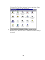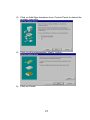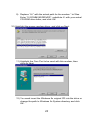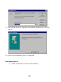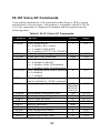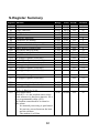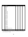
1
Communicator V.90 Internal 56Kbps Faxmodem with VoiceMail and Caller ID User Manual version3.00 Copyright © 2000 Jaton Corporation, USA UNITED STATES - FEDERAL COMMUNICATIONS COMMISSION CONSUMER INFORMATION AND REQUIREMENTS Part 15-Radio Interference This equipment has been test and found to comply with the limits for a Class B digital device, pursuant to Part 15 of FCC rules. These limits are design to provide reasonable protection against harmful interference in a residential installation. This equipment generates, uses, and can radiate radio frequency energy if is not installed and used in accordance with the instructions. It is may causes harmful interference to radio communications. However, there is no guarantee that interference will not occur in a particular installation. If this equipment does cause harmful interference to radio or television reception, please turning the it off is determination. The user encouraged to try to correct the interference by one or more of the following measures: 1. 2. 3. 4. Reorient the receiving antenna Increase the separation between the equipment and the receiver Connect the equipment into an outlet on a circuit different from that to which the receiver is connected Consult with the dealer or an experienced radio or television technician for help. Notice 1: The changes or modifications not expressly approved by the party responsible for compliance could void the user's authority to operate the equipment Notice 2: Shielded interface cables and AC. power cord, if any, must be used in order to comply with emission limits Part 68 --Telephone Connection This equipment complies with Part 68 of the FCC Rules. Inside this equipment was a label that contains, among other things, the FCC Registration Number and Ringer Equipment Number (REN) for this equipment. You must, upon request, provide this information to your telephone company. The REN is useful to determine the quantity of devices you may connect to your telephone line and still have all those devices ring when your telephone number might call. In most, but not all areas, the sum of the REN's of all devices you may connect to one line should not exceed five (.5.0). To be certain of the number of devices you may connect to your line, as determined by the REN. You should contact your local telephone company to determine the maximum REN for your calling area. If your equipment cause harm to another telephone equipment, the Telephone Company may discontinue your service temporarily. If possible, they will notify you in advance. Instead of advance notification is not possible and you will be notify as soon as possible. You will be inform of your right to file a complaint with the FCC. Your telephone company may make changes in its facilities, equipment, operations or procedures that would affect the proper functioning of your equipment. You will be notify in advance to give you an opportunity to maintain uninterrupted telephone service. ii If you experience trouble with this telephone equipment, please contact Technical Support of your OEM supplier. The telephone company may ask that you disconnect this equipment from the network until the problem has been correct or until you are sure that the equipment is not malfunctioning. This equipment might not be use on coin service provided by the telephone company. Connection to party lines is subject to state tariffs. Statement of Fax Branding The Telephone Consumer Protection Act of 1991 makes it unlawful statement which for all people. Every one who uses a computer or other electronic device to send any message via a telephone fax machine, must be clearly contains a margin at the top or bottom of each transmitted page. The first page of the transmission, the date and time it sent and an identification of the huskiness or other entity. CANADA-DEPARTMENT OF COMMUNICATIONS NOTICE Telephone Connection The Canadian Department of Communications label identifies certified equipment. This certification means that the equipment meets certain telecommunications network protective, operational and safety requirements. The department does not guarantee the equipment will operate to the user's satisfaction. Before installing this equipment, users should assure that it is permissible to be connect to the facilities of the local telecommunications company. The equipment must also be install using an acceptable method of connection. In some cases, the company's inside wiring associated with a single line individual service may be extend by means of a certified connector assembly (telephone extension cord). The customer should be aware that compliance with the above conditions may not prevent degradation of service in some situations. Repairs to certified equipment should be handle with by an authorized Canadian maintenance facility designated by the supplier. Any repairs or alterations made by the user to this equipment or equipment malfunctions, may give the telecommunications company cause to request the user to disconnect the equipment. The user should assure for their own protection. That the electrical ground connections of the power utility, telephone lines and internal metallic water pipe systems, if present, are connected together This precaution may be particularly important in rural areas. CAUTION: Users should not attempt to make such connections themselves, but should contact the appropriate electric inspection authority, or electrician, as appropriate. The Load Number 2 assigned to each terminal device connotes the percentage of the total load to be connect to a telephone loop that is use by the device, to prevent overloading. The termination on a iii loop may consist of any combination of devices subject only to the requirement that the total of the Load Numbers of all the devices does not exceed 100. iv NOTICE: The information in this document is subject to change in order to improve reliability, design, or function without subsequent notice and does not represent a commitment on the part of this company. The information in this manual is believe to be accurate. However, we assume no responsibilities for any inaccuracies that may be contain in this manual. In no event will we be liable for direct, indirect, special, incidental, or consequential damages arising out of the use. The inability is use to the product or documentation, even if advised of the possibility of such damages. No part of this reference manual may be reproduced or transmitted in any form or by any means without the subsequent written permission. This product is not designed for use in life critical situations. This product component or support assistance by manufacturer is within a period time only. Life support devices or systems are define as devices that are Intended for surgical implant into the body. For support or sustaining life and whose failure to perform with the instructions provided by the manufacturer, might result in injury to the user. June, 1999 Rev.A TRADEMARK ACKNOWLEDGMENTS Microsoft and Microsoft Windows are register trademarks of Microsoft Corp. All other product names or trademarks are property of their respective owners. Copyright protection claimed includes all forms and matters of copyrightable material and information. Now allowed by statutory or judicious law or hereinafter granted, including without limitation, material generated from the software programs that are display on the screen such as icons, screen display looks, etc. Reproduction or disassembly of embedded computer programs or algorithms prohibited. v Table of Contents CHAPTER 1 INTRODUCTION................................................................8 FEATURES ..................................................................................................8 SPECIFICATIONS..........................................................................................9 SYSTEM REQUIREMENTS ............................................................................10 MODES OF OPERATIONS ............................................................................10 CHECK LIST:.............................................................................................13 CUSTOMER SUPPORT .................................................................................13 CHAPTER 2 HARDWARE ......................................................................14 BOARD LAYOUT .......................................................................................14 MODEM INTERFACES.................................................................................15 HARDWARE INSTALLATION STEPS: ............................................................16 CHAPTER 3 SOFTWARE .......................................................................18 SOFTWARE INSTALLATION ........................................................................33 CHAPTER 4 TROUBLE SHOOTING....................................................35 MODEM BASIC ..........................................................................................35 TECHNICAL TIPS .......................................................................................39 PROBLEMS AND SOLUTIONS: ......................................................................40 CHAPTER 5 AT COMMANDS...............................................................44 OVERVIEW ...............................................................................................44 AT COMMANDS........................................................................................45 V.42/V.42BIS MNP AT COMMANDS .........................................................55 DATA ERROR CORRECTION AND COMPRESSION ..........................................55 FAX CLASS 1 AT COMMANDS ...................................................................57 IS-101 VOICE AT COMMANDS ..................................................................59 V.80 VIDEOCONFERENCING MODE COMMANDS .........................................61 S-REGISTER SUMMARY .............................................................................62 LIMITED WARRANTY. ............................................................................65 OTHER LIMITS. .........................................................................................65 EXCLUSIVE OBLIGATION. ..........................................................................65 OTHER STATEMENTS. ...............................................................................66 vi TERMS AND CONDITIONS. ......................................................................... 66 SERVICES AGREEMENT:............................................................................. 66 ENTIRE OBLIGATION. ............................................................................... 67 REDUCING WARRANTY CLAIM REJECTIONS. ................................... 67 vii CHAPTER 1 INTRODUCTION Congratulations on you purchase The Communicator V.90 to manage your desktop multimedia demands and communication needs. The Communicator V.90 transforms your computer into a fax machine, a data terminal, an Internet connection, a voice mail system, and a speakerphone. The 56kbps Fax/Data/Voice modem supports industry-standard feature for data, fax, and voice applications, plus advanced features such as 56kbps Internet download with V.90 ITU-T,full duplex speakerphone, and caller ID. This hardware reference manual contains all the information you need to install and configure with your Communicator V.90 card. You should still retain this manual for future reference. Features • V.90 ITU-T standard modulation • V.34, V.32 bis, V.32, V.22 bis, V.22A/B, V.23, V.21, Bell 212A, Bell 103 Data Modem • V.42 LAPM, MNP 2-4, and MNP 10 error correction • V.42 bis and MNP 5 data compression • V.17 Fax Modem send and receive rates up to 14,400 bps • V.80 Videoconference synchronous access modes support host based communication protocols, e.g. H.324 Videoconferencing • IS 101 Standard Voice Modem • Voice compression: ADPCM, linear, and CL1 • Full Duplex Speakerphone (INTEL / AMBIENT MD5662 only) • Caller ID and distinctive ring detect • NVRAM directory and stored profiles • Built-in DTE interface parallel 16550A UART compatible 8 • Integrated data communication, Fax, Voice software • Plug and Play or Jumper Select Configuration Specifications Modem Communication: Data Communication Standards Modulation: V.90, V.34, V.32bis, V.32 V.23, V.22bis, V.22, V.21 and Bell 212A & 103 Data Rates: 57.3K, 56K, 54.7K, 53.3K, 52K, 50.7K, 49.3K, 48K, 33.6K, 31.2K, 28.8K, 26.4K, 24K, 21.6K, 19.2K, 16.8K, 14.4K, 12K, 9600, 7200, 4800, 2400, 1200 and 300 bps Integrity: Compression: Commands: V.42 LAPM, MNP 2-4, and MNP 10 error correction V.42 bis or MNP Class 5 AT & V.25bis AT Voice Fax Standards Modulation: Data Rate: Format: Handshake: Commands: ITU-T V.17, V.29, V.27 ter, and V.21 channel 2 14,400, 12,000, 9600, 7200, 4800, 2400, 300 bps ITU-T T.4 Group 3 Fax ITU-T T.30 Group 3 Fax EIA/TIA-578 data/fax Class 1 Voice Standards Commands: Voice Sample Rate: Voice Compression: EIA/TIA IS-101 4800, 7200, 8000, 9600, 11025 samples per second ADPCM, linear, CL1 Physical/Electrical/Environmental Dimensions: Cables: 3.5" x 6.2" ( 14 cm x 15.7 cm ) 6’ Phone cord with RJ11 jack 9 Connectors: Speaker Interface: Humidity: Temperature: Humidity: Transmit Level: Receive Level: 2 RJ11 jacks for telephone and PSTN line connections Minimum load 8 Ohm, Maximum load 100 Ohm 20-90% (non-condensing) 0° to 70° C (32° to 158° F) 20-90% (non-condensing) -10 dBm ±1 dB dial-up; Programmable. -9 to -43 dBm. DCD is deactivated below -48dBm. System requirements • x86 Compatible PC with one free 16-bit ISA Expansion Slot • Quad speed or faster CD-ROM drive • Hard Disk Drive with 10MB or more available free space • Microphone, speakers or headset (for audio application) Modes of Operations The Communicator V.90 provide the complete modem functions for the following modes: Group 3 fax, data, voice, V.42/MNP 2-4, and V.42 bis/MNP 5 (Microcom Networking Protocol Class 5). Each mode has its own unique AT command set. Additionally, the modem provides special modes of operation for power management. DATA MODE In the data mode, the modem allows data to be received at speed up to 56 kbps. Taking advantage of the PSTN, which is primarily digital except for the central office local loop, this modem is ideal for remote access applications such as Internet Service Provider, On-line service, or corporate site. As a client modem, data can be sent at speed up to 31.2 kbps. As a V.34 data modem, the modem operates at line speeds up to 33.6 kbps. Error correction and data compression maximize data transfer integrity and boost average data throughput up to 115.2 kbps. 10 It implements all data rates and modulation schemes for IT-U (formally CCITT) standards V.34, V.32bis, V.32, V.22bis, V.22, V.21, Bell 212A, and Bell 103. The INTEL / AMBIENT MD5662 implements a standard data mode AT command set. This is compatible with any communication application software that supports the Hayes AT command set. V.42/MNP 2-4 AND V.42 BIS/MNP 5 MODES The modem supports error correction(V.42/MNP 2-4) and data compression (V.42 bis/MNP 5). Error correction ensures error-free data transfer. Data compression substantially increases the modem data throughput over the basic data rate. Depending on the data stream, MNP 5 may provide up to 2to-1 compression. Alternately, CCITT V.42 bis may provide up to 4:1 compression. FAX MODE In the fax mode, the modem operate at up to 14,400 bps (transmit and receive) and implement all the data rates and modulation schemes for CCITT standards V.17, V.29, V.27ter, and V.21 channel 2. The Cirrus/Ambient chipset implement a standard fax command set compatible with any communication application software that supports EIA/TIA-578 Fax Class 1 standards. VOICE/AUDIO MODE In voice/audio mode, enhanced 2-bit or 4-bit per sample ADPCM coding and decoding at 7200Hz sample rate allows efficient digital storage of voice/audio. This mode supports digital telephone answering machine, voice annotation, and audio recording and playback application. TELEPHONE-EMULATION MODE This mode allows a microphone-speaker and modem to be used as a complete telephone. In Telephone emulation mode, the received data from the microphone interface is looped back to the SAFE analog transmit pins. In voice mode, the message record and playback abilities are accessed by the extended AT command set. 11 VIDEOCONFERENCING (V.80) SUPPORT The Communicator V.90 supports IT-U V.80 recommendations. This feature ensures compatibility with host-based H.324 videoconferencing application software. The INTEL / AMBIENT MD56xx chipsets support both transparent and framed submodes of the V.80 synchronous access mode. POWER MANAGEMENT MODES The Cirrus/Ambient chipset provide sleep mode to reduce power consumption when the modem inactive. In operational mode, the modem chipset is fully powered and is either communicating with the host and/or another modem or is performing internal processing. The modem is considered to be in an inactive state when: 1. No internal processing is being performed. 2. No activity occurs between the host and the modem within a specific time. 3. The modem is on-hook. The mode exits sleep mode whenever the host writes the modem or when a ring signal is detected. CALLER ID Caller ID is a service that allows the called party know the caller’s telephone number before the call is answered. The information transmitted to the called party via Caller ID includes the call date, the call time, and the call number. This service is not available everywhere due to Central Office telephone equipment limitations and legal prohibition in some locations. Subscription for this service is usually available at a small monthly fee. For more information on how to use this feature, please refer to the communication software user’s guide. 12 Check List: Your package includes the following items: • The Communicator V.90 Faxmodem • Software & Document CD • Quick Start Guide (printed) • Telephone Cable with RJ11 Jack Customer Support If you have any questions regarding this product, please refer to this User’s Manual and README files on the Software and Documentation CD-ROM first. Updated drivers and utilities are available through Jaton BBS and Web site. Telephone: (408) 934-9369, 9-5 PST Mon.-Fri. Fax: (408) 942-6699 24 hour BBS: (408) 263-8529, 8-N-1. Internet: http://www.jaton.com E-mail: modemsupport @ jaton.com 13 CHAPTER 2 HARDWARE Read all the instructions carefully before you start. !! WARNING !! Discharge static electricity by touching the GROUND such as metal part of your case connected with good power ground before you handle the electronic circuit boards. The manufacturer assumes no liability for any damage, caused directly or indirectly, by improper installation of any components by unauthorized service personnel. If you do not feel comfortable performing the installation, consult with a qualified computer technician. Board Layout SPEAKER EPH (Optional) MICROPHONE LINE PHONE 1 3 5 7 PORT IRQ COM 1 COM 2 COM 3 COM 4 4 3 4 3 PNP 9 11 13 15 17 19 21 23 25 27 JUMPER ON 5 1 3 1 7 7 5 3 9 Thru 27 11 9 11 9 Jumper On Jumper Off Fig. 1 Board Layout Copyright ©1997 Jaton Corporation , USA. 14 HARDWARE JUMPER SETTING: Your modem can be set to either Plug and Play or manual operation. It is recommended to use PnP if you have Windows®9x Plug and Play Operating System. Otherwise, use jumpers to manually setup the Communication Port Address and Interrupt. COM PORT JUMPER SELECT: COM PORT COM 1 COM 2 COM 3 COM 4 PnP I/O Address 03F8h 02F8h 03E8h 02E8h PnP IRQ (Interrupt) 4 3 4 3 PnP Jumpers 5, 7, 11 1, 7, 9 3, 5, 11 1, 3, 9 9 through 27 Modem Interfaces SPEAKER INTERFACE The modem chipset internally implements both the volume control and amplifier necessary to drive an external speaker. The internal amplifier is capable of driving a minimum load of 8 ohm up to a maximum load of 100 ohm. The speaker volume is controlled by the ATLn command. EARPHONE INTERFACE The modem chipset implements the volume control to an external earphone. Before you wear the ear piece, make sure it is connected to the earphone jack. MICROPHONE INTERFACE The modem provides a microphone interface that connects a microphone to the modem. This microphone input can be used for local voice record mode or for Telephone-Emulation mode. 15 Hardware Installation Steps: 1. Switch off your system and all peripheral devices, and unplug the power cord from the wall outlet. Tour power cord and wall outlet may differ from the ones shown. 2. Touch a metal plate on your system to ground yourself and discharge any static electricity. 3. Remove the cover from your system. 16 4. Find a free 16-bit expansion slot in your system. 5. Remove the metal plate from the slot you have chosen and put the screw aside. 6. Align the card to a 16-bit Bus with the expansion slot and gently push down into it. Secure the card to expansion slot with the screw you removed from the metal plate. 7. Replace the cover of your system and connect necessary devices. 17 CHAPTER 3 SOFTWARE Once The Communicator V.90 card is configured with proper jumpers for the hardware and installed in the PC system, it is ready to use. Driver installation The Windows®9x operating system require you to install proper modem drivers. You may either install the Standard Modem drivers or install manufacture’s modem driver. Have the driver disk and operating system disk handy before you install the driver. WINDOWS®9X DRIVER INSTALLATION: 1) If your modem is set to PnP, when Windows 9x starts up again after the new board is installed in the system, it will detect the new hardware devices, and prompt you to install proper drivers for the devices. Select “Driver from disk provided by hardware manufacture” and click “OK”. Go to step 9). If you select alternate drivers, you may change the drivers later. If you set the modem Com port and IRQ manually, you may not see the above screen automatically. Simply insert the CD into the CD-ROM drive, the “SUPER.EXE” program will search for valid modem and guide you through the driver installation. However you may also follow the MS 18 Windows®9x “Add New Hardware” routine as below: Open the Control Panel from My Computer. 2) If you previously installed a modem, please click on Modems icon, otherwise click on Add New Hardware and go to step 4). 19 3) Click on “Remove” button on the Modems Property screen, and then click on “Add…” button. Click on next. Go to Step 6). 20 4) Click on Add New hardware from Control Panel to detect the modem manually. 5) Click on all corresponding “Next>” button. 6) Click on Finish. 21 7) Click on Change. 8) Click on “Have Disk…” button. 22 9) Replace “A:\” with the actual path for the modem *.inf files. Enter “X:\COMMV90\DRIVER”, substitute X: with your actual CD-ROM drive letter, and click OK. 10) Highlight the proper modem driver, and click on Next. 11) Highlight the Com Port to be used with this modem, then click on Next. 12) You need insert the Windows 9x original CD into the drive or change the path to Windows 9x System directory and click OK. 23 13) After all the files are copied to the installed Windows 95, click on Finish. 14) The driver installation, now is completed. DIAGNOSTICS 1) Click on Modems on the Control Panel. 24 2) Click on Diagnostics tab. 25 3) Click on the modem installed. And then click on “More Info…” 4) If the modem is installed properly, it will report your modem’s information. Otherwise, you may follow the Windows®9x modem trouble shooting routine. 26 The response from each AT Command on your actual computer screen may be different then above. DIAL-UP WITH HYPER TERMINAL HyperTerminal is under Windows®9x program “Accessories” 27 Double click on Hypertrm.exe. Enter the session name “testing” and click OK. 28 Enter a dumb Phone number, such as “1234” and click on OK. click on “Dial” button. If your modem is not installed properly, you may get this: 29 Otherwise, you will hear the dial tone from modem. Press “Esc” key on your keyboard to cancel. You will be in command state. You will be able to type in AT commands and control your modem directly. This is a great way to check out if your modem is actually working or not. Of course, this is not the way you usually use your modem. That is why we provided you an award wining communication software to make your data communication easier. If you have encountered some difficulty using the modem, you may Click on Properties on “Modem property” on Control Panel. 30 Change the Maximum speed if necessary. 31 Click on Advanced… 32 Check mark the Record a log file (ModemLog.txt in Windows®9x) for diagnostic purpose. Software Installation Once the modem hardware installed and configured properly, you may use the modem with any PC communication software. The bundled software package is pre-configured for optimal performance with your modem. Please refer to the software user’s guide for additional information. If you are using an other communications software, please follows the suggestions: 1. You must indicate to your communications software which COM Port and IRQ has been assign to your modem. 2. Set the Data Rate to: 115.2 kbps. Do not select 28,800 or 14,400 bps as serial port rates. 3. Set the Flow Control to: Hardware (or RTS/CTS) 4. Turn Auto Baud off (or Lock Baud Rate on) 5. Set Terminal Emulator to: ANSI 33 For Fax Set-up: 1. Set the Flow Control to: Hardware (or RTS/CTS) 2. Set Class 1 fax class. COMMUNICATOR V.90 CD-ROM After Windows®9x started, a welcome screen will appear when the Communicator V.90 CD-ROM is inserted to the CD-ROM drive. 34 CHAPTER 4 TROUBLE SHOOTING Modem Basic This chapter will address some basic terminology associated with your modem and with your communications software. MODEM Modem is an abbreviation of Modulator and DEModulator. It is use for computer communication. Modem translates computer data to analog signal (modulation) that can travels through the telephone network and reaches the other modem. The remote modem translates the analog signal received back to data (demodulation) and sends to the receiving end computer. FAX MODEM Most modem device designed to have the fax transmitting (or and) receiving function(s). VOICE MODEM Modem with digitized voice capability can digitize the incoming voice message and the computer can store it as a file. The voice modem can also playback a recorded digital voice message either locally or to the line as an announcement. DTE / DCE DTE stands for Data Terminal Equipment and DCE stands for Data Communication Equipment. The Computer or terminal is the DTE and the modem is the DCE. DSP Digital Signal Processor. It performs all digital signal processing functions for the chipset, such as modulation schemes and modem handshakes. UART UART (Universal Asynchronous Receiver Transmitter) is the device used in DTE or DCE for asynchronous data receiving and transmitting. The normal UART device used in PC is NS16450. For high-speed serial data receiving 35 (38500 bps and up), the PC may not be fast enough and data may become lost. In this case, a UART with data buffer is need such as NS16550A. NVRAM NVRAM(Non-Volatile RAM) is a device to store the DCE configuration. Upon powering-up, the modem defaults to the configuration specified in the NVRAM or to the factory default (if the NVRAM was not installed). DCE configuration can be changed and stored by DTE in the NVRAM by first setting up the current configuration and then sending an AT command &Wn. The active profile will be lost if reset commands were issued or the modem is not powered. For examples: ATZ Resets and then configures the modem to NVRAM user profile 0. AT&F S0=1 &W1 &Y1 &F configures the modem to factory default &S0=1 configure the modem to answer after one ring &W1 saves the active configuration to profile 1 &Y1 Configure the modem to use NVRAM user profile 1 as the power-up defaults. AT COMMAND SET AND S-REGISTER The modem (DCE) operates in one of two states: command or on-line. In each state, data and commands (including DCE response) are both transfer through the UART. In command state, the host (DTE) communicates to the modem through AT (stands for attention) commands and S-registers. AT command set is the industry standard used to control the modem in command state. S-registers are internal modem registers that DTE can access. AT command set extended by each modem manufacture for the control of more modem functions and capabilities. For more information, please refer to the Chapter 5 AT Commands. INITIALIZATION STRINGS An Initialization string is a series of specific commands that prepares a modem to operate with communications software. Consult with your 36 Communication software manual and AT Command to modify INIT strings. XMODEM, YMODEM, ZMODEM These are file transfer protocols used by the host ( i.e. communication program in the PC). It does error checking and assures data integrity of the file transfer. There are some other protocols. ZMODEM is the most preferred protocol to use. DATA RATE The modem recognizes AT commands from the DTE, at any valid data rate from 300 bps to 115,200 bps. However, the DTE should use the data rate specified for each mode: Mode Data (V.34) Data(Tran smit) Data( Receive) Data( Receive) Fax Voice Data Rate (bps) 300-33,600 300-115,200 4800-31,200 Affected Data Modem-to-modem data rates DTE-to-modem data rates Modem-to-modem data rates 33,333-57,333 ISP-to modem data rates 300-115,200 DTE-to-modem data rates 19,200 19,200115,200 AT commends and fax data transfers AT commands, playback and record modes (Varies according to compression type) MNP Microcom Network Protocol is a data communication protocol that allows error-free interactive communications with a variety of computers or terminals over ordinary voice-grade telephone lines. LAPM Link Access Procedure for Modems. An HDLC error correction protocol is for use with error-correcting modems. Part of the CCITT V.42 protocol. 37 XON/XOFF A handshaking, flow control mechanism that communicates that the device is ready to accept more data. The flow control embedded into the data stream by using special characters with hence transmit on (XON), or transmit off (XOFF) often referred to as software flow control. CTS/RTS CTS stands for Clear To Send. RTS stands for Request To Send, a handshake line in which the computer tells the modem it can accept new data. DCD Data Carrier Detect DSR Data Set Ready. Supplied by the modem to indicate it has power and is ready to accept commands. DTR Data Terminal Ready. Signal generated by the computer to indicate it can accept data from the modem. DUPLEX A communication system that is capable of communicating in both directions can be half duplex or full duplex. Half duplex allows communication in both directions, but only one direction at a time, while full duplex allows data to transmitted in two directions simultaneously. OFF-HOOK Pick-up a telephone receiver. You take the modem off hook to dial or answer and it remains off hook while you are connected. ON-HOOK Hangs up a telephone receiver. You are not connected to Telephone Central Office when the modem is on hook. 38 DTMF Dual-Tone-Multi-Frequency. The use of two simultaneous audio band tones for dialing. CCITT Acronym for the International Telegraph and Telephone Consultative Committee. An international organization that decides upon recommended communication protocol standards. Also see ITU-T. ITU-T International Telecommunication Union-Telecom. Formerly CCITT. Technical tips 1. Make sure the modem card is fully insert into the expansion slot. 2. Check to make sure that the phone and line cables connected to the correct jacks on the back of the modem. Some communications software packages allow you to set the initialization (INIT), dialing, hang-up, and auto answer command strings. In doing so, you may encounter problems with the following commands: E0 The use of this command results in an apparent loss of command echo from the modem. Solution: Change the command to E1(Default). M0 This command disables the monitor speaker, not allowing you to monitor either the dialing or call progress. Solution: Change the command to M1(Default). Q1 When this command set, the modem will not return any result code. Change the command to Q0(Default). Sn=x This command is use to directly set an S-register value. Some registrars were well define (i.e. S0.) Other registrars are bit-mapped and their operation will vary depending on the modem type and configuration. Typically, S-registers store parameters set by other AT 39 commands. V0 This command causes the result codes to issued in numeric code(which may require for some software packages.) However, if you want the result codes to appear in English text, you will have to change the command to V1. Xn This command determines Result Code Type. For some values of n, the modem will dial without dial tone or BUSY signal detection. The modem may not report the connect data rate. Solution: Change the command to X4. Problems and solutions: Problem: Modem would not dial Solution: Check your phone line and cable connections. Make sure that the line from the wall connected to the LINE jack of the modem. Problem: No dial tone message Solution: Make sure no other phone extension has picked up on the same line. Make sure that the telephone line, coming from the wall connected to the LINE jack and NOT to the PHONE jack on your modem. Check to make sure you are using a standard analog telephone line and not a digital line. Problem: Modem does not dial correctly Solution A: Your phone system may require that you obtain an outside line before dialing. In this case, place the numeric prefix for the outside line (usually the number 9) before the phone number in your dialing string. 9 555 3333 To get out of the office NOTE: Place a comma immediately after the number 9 in the dialing string to create a 2 second delay at that point in the dialing. This prevents the modem from dialing the phone number before the phone system has had time to connect to 40 an outside line. 9, 555 3333 To get a pause Solution B: You may be trying to dial into another area code; you must first dial a 1 before the phone number in your dialing string. 1 555 555 3333 To get into another area code The other end could be busy or not answering. Make sure the number you dialed is correct. Test the number by dialing it on your telephone - not through your modem. If you are using the modem internationally, your modem may not recognize the dial tone in the local country. Try the command ATX3DT and the telephone number. 41 Problem: Error message Solution: Make sure you selected the correct modem in your communications software. If you are typing from the command line in terminal mode, make sure you typed correctly. Make sure you are issuing the correct AT command. Note: Not all modems support the same AT Command set. Check the AT Command set in this manual to assure that you are using a valid AT Command. Problem: Modem communication error or modem not found Solution: Make sure you have selected the correct COM Port in your communications software setup. Check all the cable connections and make sure they are secure. In fax software, make sure you have selected the correct fax class. The Port setting in the Control Panel in Windows may not set properly. Problem: Solution: Modem would not connect. If you have no trouble communicating with any modem except on one particular line, the problem may be with the modem on the other end of that line. Problem: Modem would not fax Solution: Make sure you have selected Class 1 fax class. Make sure that you do not have another communication program open. Be sure you selected the Fax printer in your word processing program. Problem: Fax not found Solution: Re-install or re-setup Fax software with the modem installed. The Port setting in the Control Panel in Windows may not set properly; You may have connected the phone line, coming 42 from the wall, to the Phone jack on the back of the modem. The phone line, coming from the wall, must connect to the Line jack. Problem: Modem does not respond to AT Commands Solution: Make sure the COM port settings in the software match the hardware configuration. Make sure the board seated properly (pushed all the way into the slot). 43 CHAPTER 5 AT COMMANDS Overview The modem (DCE) operates in two states: command or online. In each mode, both data and commands (including DCE responses) are transferred through the UART THR (Transmit Hold register) and the RBR (Receiver Buffer register). The modem defaults to the command state. In this command state, the host (DTE) communicates to the modem through AT commands and S-registers. S-registers contain modem status and configuration information that DTE can access. AT commands are character strings that guide modem operation. Many of AT commands indirectly affect the contents of Sregisters. • An AT command string begins with an AT prefix and ends with a carriage return character defined in S-Register 3 (default: <↵ Enter>). The A/ (repeat last command) and +++ Escape sequences are the only exceptions. • AT command strings can contain multiple commands in the same string. These commands are placed after the AT prefix and before the <↵ Enter>. Spaces may be used to separate commands within the string. • Each command line may include up to 80 characters and spaces. • The AT prefix and commands may be in either upper or lower case, but all characters for the given command must use the same case. • For commands that contain numeric options you may omit the numeric value and the modem will assume that the number 0 was entered. • While the modem is attempting to connect to a remote modem, any character entered is considered an ABORT command. The modem will go on-hook and enter the command mode. 44 AT Commands Table 1. Basic AT Commands Command Description A/ Repeat the last AT command string issued. An “AT” prefix is not used. Do not terminate this command with <ENTER>. Write to selected S-register. Read selected S-register. Answer. Go off-hook and enter the answer mode. After 3 seconds the modem will initiate an answer tone. Bell/CCITT (Default=1) Use CCITT V.22 at 1200 bps, and CCITT V.21at 300 bps Use Bell 212A at 1200 bps, Bell 103 at 300 bps. Dial number n (Default=T) 0-9 Digits 0 to 9, Touch-tone or Pulse dialing. * The star digit (Touch-tone only.) # The gate digit (Touch-tone only.) A-D Digits A, B, C and D: (Touch-tone only.) P Pulse dialing. R Reverse originate mode S=n Dial the stored number(NVRAM), n=0 to 3. (See &Z) T Touch-tone dialing. W Wait for dial tone. The modem will abort if the dial tone is not detected within the time specified by S7. @ Wait for quiet answer. ! Flash. hook , Pause; the modem will pause for a time specified by S8 before dialing the digits following “,” ; Return to idle state -() Ignored by modem Command Echo (Default=l) Disables command echo from the modem. Enables command echo from the modem. Hook Switch Control (Default=0) Modem goes on-hook. AT= x AT? A Bn B0 B1 Dn En E0 E1 Hn H0 45 H1 Modem goes off-hook. 46 Command Description In Identification Display product code. Display firmware checksum. Verify firmware checksum. (Report OK if correct.) Display firmware revision. Display identifier string. Display country code. Display Data Pump modem and revision. Speaker Volume (Default=1) Low volume. Medium volume. High volume. Speaker On/Off (Default=1) Speaker always off. Speaker on until modem detects the carrier signal. Speaker is always on when modem is off-hook. Speaker off during dialing, on after dialing until modem detects the carrier signal. Automode Enable/Disable (Default=1) This command is provided for compatibility. The +MS extended format command should be used with new applications. Automode disabled, connect at the data rate defined by S37. Automode enabled. Return Online Instructs the modem to exit Online Command mode and return to Data Mode. Pulse Dial (Default=T) Result Codes (Default = 0) Enables display of result codes. Disables display of result codes. Write S Register Write the value v into S Register n. Read S Register. Report the value of S Register n. Tone Dial (Default=T) Result Codes Format (Default=1) Enable short-form result codes. (Numeric) I0 I1 I2 I3 I4 I5 I6 Ln L0,1 L2 L3 Mn M0 M1 M2 M3 Nn N0 N1 O P Qn Q0 Q1 Sn Sn=v Sn? T Vn V0 47 V1 Enable long-form result code. (Text or Verbose) 48 Command Description Wn Connect Message (Default=0) This command is provided for compatibility. The S95 Register should be used with new applications. Reports only the DTE speed. Reports the DCE speed, protocol, and DTE speed. Reports only the DCE speed. Extended Result Codes end Call Progress Options (Default=4) W0 W1 W2 Xn Ext. Result Code X0 Disable X1 Enable X2 Enable X3 Enable X4 Enable Yn Y0 Y1 Zn Z0 Dial Tone Detect Disable Disable Enable Disable Enable Busy Tone Detect Disable Disable Disable Enable Enable Extended Result Codes: Disabled: Displays only the basic result codes OK, CONNECT, RING, NO CARRIER, ERROR. Enabled: Displays basic result codes, along with the connect message and the connect data rate. Dial Tone Detect: Disabled: The modem waits the period of time specified by S6 and then dials a call regardless of whether it detects a dial tone. (Blind Dialing) Enabled: The modem dials only upon detection of dial tone, and disconnects the modem if the dial tone is not detected within the period of time specified by S6. Busy Tone Detect: Disabled: The modem ignores any busy tones it receives. Enabled: The modem monitors for busy tones. Long Space Disconnect (Default=0) Disable Long Space Disconnect. Enable Long Space Disconnect generation and response. Soft Reset and Reload Active Profile Soft reset and reload active profile from stored profile 0. 49 Z1 &Cn &C0 &C1 Soft reset and reload active profile from stored profile 1. DCD (Data Carrier Detect) option (Default=1) Ignore remote modem status; DCD allways on DCD set according to remote modem status Command Description &Dn DTR(Data Terminal Ready) option, (Default=2) In async mode, modem ignores the status of DTR . Modem switches from data mode to command mode when an on-to-off transition of DTR occurs. If the DTR signal goes off, then the modem disconnects and disables auto-answer mode. Auto-answer is enabled when the DTR signal is on. Turning off DTR re-initializes the modem and resets values except UART registers Restore Factory Default Configuration Guard tone option (1200 bps and 2400 bps only) Disables guard tone Enables 550Hz guard tone Enables 1800Hz guard tone Flow Control (Data Default=3, Fax Default=6) Disables flow control. Enables bidirectional hardware flow control (RTS/CTS) Enables Xon/Xoff software flow control. Communication mode control-asynchronized mode only Dial pulse ratio Sets 10-pps pulse dial with 39%/61% make-break Sets 10-pps pulse dial with 33%/67% make-break Communication mode control-asynchronized mode only DSR (Data Set Ready) Option (Default=0) DSR will remain ON at all times. DSR will become active only during handshaking and the carrier is lost. Self-test commands (Default=0) Terminate test in progress. Initiate Local Analog Loopback. Initiate Local Digital Loopback. Grants RDL request from remote modem &D0 &D1 &D2 &D3 &Fn &Gn &G0 &G1 &G2 &Kn &K0 &K3 &K4 &M0 &Pn &P0 &P1 &Q0 &Sn &S0 &S1 &Tn &T0 &T1 &T3 &T4 50 &T5 &T6 &T7 &T8 &Un &U0 &U1 Denies RDL request from remote modem Initiate remote digital loopback. Starts remote digital loopback with self test. Initiate Local Analog Loopback with self test. Trellis coding (Default=0) Enables Trellis coding with QAM as fallback QAM modulation only 51 Command Description &Vn View active and stored profiles (Default=0) View stored profile 0 View stored profile 1 View relay and GPIO status Store active profile Store the current configuration into the User Profile 0. Store the current configuration into the User Profile 1. Select stored profile on power up (Default=0) Set User Profile 0 to default on power up Set User Profile 1 to default on power up. Store Telephone Numbers (up to 30 digits) to location n (0 - 3) x=0-9 A-D # * T P R W @ , ! ; Auto-Retrain Control (Default=1) Disables auto-retrain. Enables auto-retrain. &V0 &V1 &V3 &Wn &W0 &W1 &Yn &Y0 &Y1 &Zn=x %En %E0 %E1 %Gn %G0 %G1 %L -Cn -C0 -C1 -C2 +GMI? +GMM? +GMR? +MS=m Rate renegotiation Disables Rate renegotiation Enables Rate renegotiation Reserved by manufacture Generate data modem calling tone Calling tone disabled 1300 Hz calling tone enabled V.8 calling tone and 1300 Hz calling tone Identify modem manufacture Identify product model Identify product revision Select Modulation (Default +MS=V.34, 1, 300, 0) (see note) This extended format command selects the modulation, optionally enables or disables automode, and optionally specifies the lowest and highest connection rates using up to four sub-parameters. This command replaces the Nn and S37 register functions: +MS=<carrier>[, [<automode>][, [<min_rate>][, [<max_rate>]]]] 52 53 Note: <carrier> V21 V22 V22B V23 V32 V32B V34 V34S V34B V34BS Modulation V.21 V.22 V.22bis V.23 V.32 V.32bis V.34 Asymmetrical V.34 Symmetrical Only V.34 Extended Asymmetrical V.34 Extended Symmetrical 56-kbps Transmit 56-kbps Receive Possible rate (bps) 300 1200 2400 or 1200 1200/75 9600 or 4800 14400, 12000, 9600, 7200, or 4800 33600, 31200, 28800, 26400, 24000, 21600, 19200, 16800, 14400, 12200, 9600, 7200, 4800, 2400 THE SAME AS ABOVE THE SAME AS ABOVE THE SAME AS ABOVE 4800, 7200, 9600, 12000, 14400, 16800, 19200, 21600, 24000, 26400, 28800, 31200 33,333, 37,333, 41,333, 42,667, 44,000, 45,333, 46,667, 48,000, 49,333, 50,667, 52,000, 53,333 <automode> 0 1 Automode disabled Automode enabled (Default) <min_ rate> <min_rate> is the lowest rate at which the modem may establish a connection. Set<min rate>=<max rate> to force a <max_rate> 300 to 33600 Connection at a specific rate. <max_rate> <max_rate> is the highest rate at which the modem may establish a connection. 54 V.42/V.42bis MNP AT Commands Data Error Correction and Compression Your modem supports two types of error correction (MNP2-4 and V.42) and data compression (MNP5 and V.42 bis). V.42 error correction uses LAPM as the primary error-control protocol and uses MNP2-4 as an alternate. V.42 bis data compression requires V.42 (LAPM only). MNP5 requires MNP2-4. The supported V.42 bis/MNP AT commands are listed below: Table 2. V.42/V.42 bis MNP AT Commands Command Description %An %Cn Set auto-reliable fallback character (Default=13) MNP 5 data compression control (Default=1) No compression Enables MNP5 data compression MNP Block Size (Default=3) 64 characters (This improves throughput on noisy phone line) 128 characters 192characters 256 characters Transmit Break Set auto-reliable buffer (Default=0) No data buffering Four-second buffer until 200 characters in the buffer or detection of a SYN character No buffering. Connects non-V.42 modems to V.42 modem Set modem port flow control (Default=0) Disable port flow control. Set port flow control to XON/XOFF Bps rate adjusts control (Default=0) Disables rate adjust Enables rate adjust Set break control (Default=5) %C0 %C1 \An \A0 \Al \A2 \A3 \Bn \Cn \C0 \C1 \C2 \Gn \G0 \G1 \Jn \J0 \J1 \Kn In connect state, transmits break to remote (if in reliable mode): \K0,2,4 \K1 Enters command mode, no break sent Destructive/expedited 55 \K3 \K5 Nondestructive/expedited Nondestructive/nonexpedited In command state, transmit break to remote (if in reliable mode): \K0,1 Command \K2,3 \K4,5 Destructive/expedited Description Nondestructive/expedited Nondestructive/nonexpedited In connect state, receives break at modem port (if in direct mode): \K0,2,4 \K1,3,5 Immediately sends break and enters command state Immediately sends the break through In connect state, receives break at modem port and sends to serial port: \K0,1 \K2,3 \K4,5 \T0 Destructive/expedited Nondestructive/expedited Nondestructive/nonexpedited Set operating mode (Default=3) Selects normal mode with speed buffering Selects normal mode with speed buffering Select MNP reliable mode Select V.42 auto-reliable mode Select V.42 reliable mode Originate reliable link Set serial port flow control (Default=3) Disables flow control XON/XOFF software flow control Unidirectional hardware flow control Bi-directional hardware flow control Disable inactivity timer (Default=0) \U Accept reliable link \Nn \N0 \N1 \N2 \N3 \N4 \O \Qn \Q0 \Q1 \Q2 \Q3 \Xn \X0 \X1 \Y \Z -Jn -J0 -J1 Set XON/XOFF pass-through (Default=0) Processes flow control characters Processes flow control characters and passes to local or remote Switch to reliable mode Switch to normal mode Set V.42 detect phase (Default=1) Disables the V.42 detect phase Enables the V.42 detect phase 56 “Hn “On V.42 bis compression control (Default=3) “H0 Disables V.42 bis “H1 Enables V.42 bis only when transmitting data “H2 Enables V.42 bis only when receiving data “H3 Enables V.42 bis for both transmitting and receiving data V.42 bis string length (Default=32) Fax Class 1 AT Commands Your modem implements the EIA-578 dada/fax Class 1 AT command set standard. This AT command set allows a DTE (with Class 1 communication software) and a INTEL / AMBIENT MD34xx based modem to communicate with group 3 fax machines. The fax identity and test commands listed below. Table 3. Fax Identity Commands Command Function +FMFR? +FMDL? +FMI? +FMM? +FMR? +FREV? Identify modem manufacturer Identify product model Identify modem manufacturer Identify product model Identify product version number Identify product version number Table 4. Fax Class 1 AT Commands Command Function Range +FCLASS=1 +FAE=n Mode selection (Default=0) Fax/data auto-recognition (Default=0) Receive HDLC data Receive data 0, 1, 8, 80 0, 1 +FRH=n +FRM=n 57 3 24, 48, 72, 73, 74, 96, 97, 98, 121, 122, 145, 146 +FRS=n +FTH=n +FTM=n Wait for silence Transmit HDLC data Transmit data +FTS=n Stop transmission and pause 58 1-255 3 24, 48, 72, 73, 74, 96, 97, 98, 121, 122, 145, 146 0-255 IS-101 Voice AT Commands Your modem implements a AT command set that allows a DTE to record and playback voice messages. This product is compatible with EIA/TIA IS101 voice command set. Supported commands and descriptions listed in following tables: Table 5. IS-101 Voice AT Commands Command Function Default Range +FCLASS=8 Voice mode selection 0 0-2, 8, 80 +FLO=n Flow Control Select 1 0-2 n = 0 disables flow control n = 1 enables XON/XOFF n = 2 enables CCITT V.24 CTS/RTS +VBT=m Buffer threshold setting 192, 320 192, 320 +VTS=m DTMF and Tone generation None Call +VCID=n Caller ID selection *0 0-2 n = 0 Disables Caller ID n = 1 Enables Caller ID formatted n = 2 Enables Caller ID unformatted #VCSD=n Voice command mode silence detection 0 0,1 n =0 disabled n = 1 enabled +VDR=m Distinctive Ring selection 0,0 0-255, 0-255 (can be disabled by +VEM command) +VEM=m Event reporting and masking ‘C’ Call BB860980 BFE63883 BB863EE0 +VGM=n +VGS=n +VGR=n +VGT=n +VIP=n +VIT=n +VLS=n +VNH=n +VRA=n Speakerphone microphone gain Speakerphone speaker gain Receive gain selection Volume selection Initialize parameter DTE/DCE inactivity timer Relay or playback control Automatic hang-up control Ringback-goes-away timer 59 128 128 128 128 none 0 0 0 50 121-131 121-131 121-131 121-131 0-255 0-16 0-255 0-50 +VRN=n +VRX Ringback-never-appeared timer Record mode 60 10 none 0-255 Call Command Function Default Range +VSD=m Silence detection (quiet and silence) 128, 50 0-255,0-255 +VSM=m Compression method selection 140, 8000 m=<cml>, <vsr>, <scs>, <sel> 0, 0 <cml> = 0,128 : 8-bit Linear PCM = 1,129: 16-bit Linear PCM = 132: 4-bit ADPCM = 140: 8-bit Cirrus ALaw(CL1) = 141: 3-bit ADPCM <vsr> = 4800Hz: Previous Default = 7200Hz = 8000Hz: Bulletin Boards = 9600Hz = 11KHz: Windows .WAV files <scs> = 0: Disable DCE silence compression = n+1: Noise threshold <sel> = 0 : Disable silence expansion +VSP=n Speakerphone on/off control 0 0,1 #VSPS=n Speakerphone Type Selection 0 0, 1 +VTD=n Beep tone duration timer 100 5-255 +VTX Play mode none Call V.80 Videoconferencing Mode Commands Command FCLASS=0 +A8E=m +ES=m +ESA=m Function Default Mode selection 0 V.8 and V.8 bis operation control 1, 1, C1, 0, , Error control selection 0-255 Synchronous access mode 0,0,1,,0,0,126 configuration +ITF=m Transmit flow control thresholds 320, 192, 0 8-bit in-band In-band commands and indications for non control use in synchronous access mode only 61 Range 0, 1, 8, 80 call call call call call S-Register Summary Registe S0 S1 S2 S3 S4 S5 S6 S7 S8 S9 S10 S11 S12 S14 S16 S18 S21 S22 S23 Function Rings to auto-answer Ring counter Escape character Carriage return character Line feed character Backspace character Wait before for dialing Wait for carrier Pause time for dial delay modifier Carrier detect response time Lost carrier hang up delay DTMF dialing speed Guard Time Bit-mapped options (read only) Modem Test Options (read only) Modem Test timer Bit-mapped options (read only) Bit-mapped options (read only) Bit-mapped options (read only) Range 0-255 0-25 0-255 0-127 0-127 0-255 2-255 1-255 0-255 1-255 1-255 50-255 0-255 Units Saved* Default Rings Yes 0 Rings 0 ASCII Yes 43 ASCII 13 ASCII 10 ASCII 8 1 sec Yes 2 1 sec Yes 50 1 sec Yes 2 0.1sec Yes 6 0.1sec Yes 14 0.001s Yes 70 0.02s Yes 50 Yes 170 0 0-255 1.0s Yes 0 Yes 48 Yes 118 Yes none S25 Detect DTR change S27 Bit-mapped options (read only) 0-255 0.01 s Yes Yes 5 739 S30 Disconnect inactivity timer S31 Bit-mapped options (read only) S32 Vx mode enable Bit 5 = 1, Bit 5=0, V.34 S33 Sleep mode timer When S33<>0, the modem enters sleep mode whenever it has been inactive for a user programmable delay (S33). The modem considered to be inactive state when: 1. No internal processing is performed. 2. No activity occurs between the host and the modem. 3. The modem is off-line 0-255 minute Yes Yes Yes 0 none 32 Yes 10 62 0-255 0-90 second *: SAVED in NVRAM. 63 Register Function S37 Maximum Line Speed Attempt 0=DTE rate 3=300 bps 5=1200 6=2400 7=4800 8=7200 9=9600 10=12,200 11=14,400 12=16,800 13=19,200 14=21,600 15=24,000 16=26,400 17=28,800 18=31,200 19=33,600 20=36,000 21=33,333 22=37,333 23=41,333 24=42,666 25=44,000 26=45,333 27=46,666 28=48,000 29=49,333 30=50,666 31=52,000 32=53,333 33=54,666* 34=56,000* 35=57,333* (Use +MS command for new application) S91 (Reserved) S92 (Reserved) Range 0-35 0-15 0-15 Units Saved Yes Yes Yes Default 0 10 10 *: Current download speeds are limited to 53,333bps due to FCC rules that restrict modem power output. 64 LIMITED WARRANTY. Manufacturer warrants that the products sold hereunder are free from defects in material and workmanship for a period of two (2) years from manufacturing date. This limited warranty applies only to the original purchaser of Jaton Product and is not transferable. This limited warranty does not apply if failure to the Product Registration, or over thirty (30) days from purchase (original invoice date). This Limited Warranty does not cover any incompatibilities due to the user’s computer, hardware, software or any related system configuration in which the Jaton Products interfaces. Proof of purchase will be required before any consideration by Manufacturer occurs. Other Limits. The forgoing is in lieu of all other warranties, expressed or implied. Including but not limited to the implied warranties of merchantability and fitness for a particular purpose. Manufacturer does not warrant against damages or defects arising out of improper or abnormal use of handling of the products; against defects or damages arising from improper installation (where installation is by persons other than Manufacturer), against defects in products or components not manufactured or installed by Manufacturer, or against damages result from non-manufacturer made products or components. This warranty does not apply if the Product has been damaged by accident, abuse, or misuse. This warranty also does not apply to products upon which repairs have been effected or attempted by persons other than pursuant to written authorization by Manufacturer. Exclusive Obligation. This warranty is exclusive. The sole and exclusive obligation of Manufacturer shall repair or replace the defective products in the manner and for the period provided above. Manufacturer shall not have any other obligation with respect to the Products or any part thereof, whether based on contract, tort, strict liability or otherwise. Under no circumstances, whether 65 based on this Limited Warranty or otherwise, Manufacturer shall not be liable for incidental, special, or consequential damage. Other Statements. Manufacturer’s employees or representatives’ ORAL OR OTHER WRITTEN STATEMENTS DO NOT CONSTITUE WARRANTIES, shall not be relied upon by Buyer, and are not a part of the contract for sale or this Limited Warranty. Terms and Conditions. Direct Jaton Customer: This warranty applies only for a period of two (2) years from purchase date of Jaton original invoice. Reseller/ Vendor: This warranty applies only for a period of two (2) years from manufacturing date. Registered User: This warranty applies only for a period of two (2) years from purchase date and register within 30 days of purchase date from legal reseller. Others: If the products do not conform to this Limited Warranty (as herein above described), Manufacturer will charge services fee such as repair, replacement whether based on its costs. Shipping and installation of the replacement Products or replacement parts shall be at User’s expanse. Services agreement: (1) All applicants shall complete service request form from Manufacturer. (2) All returned checks will be charged a $20.00 fee by Manufacturer. (3) All repair and replacement services allow 4-6 weeks from the date of receiving by Manufacturer. (4) All products without warranties require service processing fee $20 (payment in advance), which is not refundable. 66 Entire Obligation. This Limited Warranty states the entire obligation of Manufacturer with respect to the Products. If any part of this Limited Warranty is determined to be void or illegal, the remainder shall remain in force and effect. Some states do not allow limitation of implied warranties, or exclusive or limitation on product incidental or consequential damages, so above limitation may not apply to you. This warranty gives you specific legal rights. You may have other rights which may vary from state to state. This warranty applies only to this product, and is governed by the law of the State of California. REDUCING WARRANTY CLAIM REJECTIONS. To reduce the potential of incurring damages not covered by Manufacturers warranties, we strongly recommend the following: • • • • read your manuals before installing peripherals and/or before making changes to the machine’s configuration; ask your dealer if there are any known problems with the system requirements or installation procedures for any add-on products that your are purchasing; buy industry standard products where compatibility issue are more likely to surface; If you are unsure about installation for a new product, contact your dealer’s service department. We believe it is important for you to know and understand what your warranty coverage provides and what it does not. We also want you to be aware that most hardware warranties only cover the functions of the hardware. In most cases, no assurances are given by the manufacturer that the hardware item will work in conjunction with any other hardware item. If a computer product is not working because it is not 67 compatible with another product, or because it has not been properly installed and set-up, the manufacturer does not pay for the service time. To help avoid these inconveniences, contact a professional consultant that can help you determine the possibility of incompatibility issue before you purchase add-on products or accessories. For Reseller / Vendor Use Only Serial Number - ten or eleven digit code, the serial number consists of the following parts: Packaging Type Manufactured Date Code A 99 5 Production Numerical Code 000015 Year Month XXXXX-XXXXX S/N: A995000015 123456789123456789123456789123456789abcdefghijklmnop XXXXX 00.0 XXXX XX XXXXXXXX Product Label and Manufactured Date Code 68