1
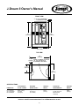
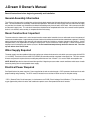
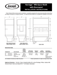
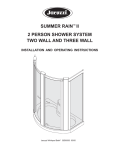
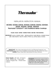
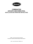
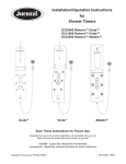
OWNER’S MANUAL
Assembly, Installation
& Operating Instructions
TM
J-DREAM II
Shower System
IMPORTANT SAFETY INFORMATION
READ ALL INSTALLATION INSTRUCTIONS
Jacuzzi Whirlpool Bath does not recommend prolonged periods of use of the steamer. Prolonged use of the steam
system can raise the internal human body temperature excessively and impair the body's ability to regulate its internal
temperature (resulting in hyperthermia). Consult your physician about your safety and comfort before using the steam
system; limit your use of steam to 10-15 minutes until you are certain of your body's reaction. A cooling shower spray
can be used simultaneously with the steam to assist in regulating your body temperature.
Alcohol, certain drugs or medications such as tranquilizers affect a person's ability to withstand high temperatures and
may produce dangerous side effects. Do not use alcohol or drugs when using the J-Dream II.
The elderly, the infirm, and children should not use the J-Dream II unattended. Pregnant women and people with heart
conditions should consult their physicians before using the steamer.
The wet surface of the J-Dream II can be slippery. Use care when entering and exiting.
When using the J-Dream II, basic safety precautions should always be followed:
This unit is to be connected to a Ground Fault Circuit Interrupter (GFCI). This is also known as an Earth Leakage Circuit
Breaker (ELCB). Check at least once a month to be sure this is operational. With the unit operating, push in the test
button. The unit should stop operating and the trip indicator should appear. Restore the power; push to OFF, then
turn ON. The unit should now operate normally. If the interrupter fails to operate in this manner, there is a fault in the
electrical system or the GFCI and you may not be protected from an electrical shock. Turn off the power and have
a qualified electrician check the circuit before using it again.
Do not use electrically connected devices such as television, radio, or stereo speakers, lights, hair dryers, or
telephones within 1.5 m (5 feet) of the J-Dream II while in use.
Read manufacturer's safety information with all optional equipment.
Note: This is a professional grade product. A good knowledge of construction techniques, plumbing and
electrical installation according to codes are required for proper installation and user satisfaction. We
recommend that a licensed contractor perform the installation of all Jacuzzi Whirlpool Bath products. Our
warranty does not cover improper installation related problems.
Save These Instructions for Future Use.
Owner's Record
Date Purchased ____________________________________________________________
Purchased From ____________________________________________________________
Installed By ________________________________________________________________
Serial Number ___________________________
(See page 2 for location of serial number.)
Contents
Part I Assembly & Installation
Specifications _______________________________________________________________________
General Information __________________________________________________________________
Packaging __________________________________________________________________________
Hardware Identification ________________________________________________________________
Rough-in ___________________________________________________________________________
Base and Drain ______________________________________________________________________
Installation of Panels __________________________________________________________________
Door Frame _________________________________________________________________________
Top Frame __________________________________________________________________________
Hose and Electrical Connections ________________________________________________________
Bonding ____________________________________________________________________________
Final Plumbing ______________________________________________________________________
Front Panels ________________________________________________________________________
Cover ______________________________________________________________________________
Completing the Installation _____________________________________________________________
2
3-4
5
6
7
8-9
10-16
17
18
19-21
22
23
24
25
26
Part II Operation and Maintenance _______________________________
27-30
33-34
Warranty _____________________________________________________________
Inspection and Shipping Claim
Check for shipping damage upon receipt of the J-Dream II. Jacuzzi Whirlpool Bath is not responsible for damage
to the J-Dream II sustained during shipping. If damage is evident before unpacking, see instructions regarding
shipping claims on the outside of the carton and immediately file a claim with the carrier.
Once the J-Dream II has been removed from the carton and before it is permanently installed, check the parts
completely for damage resulting from shipping or handling. All Jacuzzi Whirlpool Bath products are factory tested for
proper operation and watertight connections prior to shipping. If problems are detected, immediately notify your
Jacuzzi Whirlpool Bath dealer or Authorized Service Agent, or call Jacuzzi Whirlpool Bath, (800) 288-4002, for
Warranty Service.
NOTE: Damage or defects which could have been discovered and repaired prior to installation and which
are claimed after final installation of the J-Dream II, are excluded from our warranty.
1
J-Dream II Owner's Manual
R
WHIRLPOOL
BATH
FRONT VIEW
3" (76 mm) CLEARANCE
TO REMOVE DOME
83"
(2108mm)
81"
(2057mm)
60"
(1524 mm)
TOP VIEW
60"
(1524mm)
11 5/8" SERIAL NUMBER LOCATION
(295mm) (AT TOP) ON BACK OF
EQUIPMENT SEAT WALL
21 1/2"
(546mm)
42"
(1067mm)
SPECIFICATIONS
DIMENSIONS
TOTAL WEIGHT/
FLOOR LOADING
REQUIRED
WATER SUPPLY
PRODUCT
WEIGHT
ELECTRICAL
REQUIREMENTS*
SHIPPING
WEIGHT
60" (1524mm)L
42" (1067mm)W
83" (2108mm)H
833 lb (379 kg)
47.6 lb/ft2
(233 kg/m2)
6 gpm (23 liter/min)
@ 30-65 psi
(2.1-4.6 Bar)
525 lb
(239 kg)
240 VAC, 3-Wire
20 Amp, 50-60 Hz
(Must be GFCI
Protected)
849 lb
(386 kg)
* Unit supplied with a 240 VAC, 20 Amp, 3 wire plug (NEMA 6-20P).
PRODUCT SPECIFICATIONS ARE SUBJECT TO CHANGE WITHOUT NOTICE.
2
J-Dream II Owner's Manual
Read all instructions before beginning assembly and installation.
General Assembly Information
The J-Dream II shower unit is installed into a niche with the drain towards the left hand side of the unit as you face the shower
door. This manual details the assembly, installation and operation. After the drain, water supply stub-out, and electrical supply
are provided, the shower unit should be assembled freestanding away from the walls of the room. Next connect and static
test the water supply lines. The electrical connections should then be completed before the unit is moved into final position,
drain fit is rechecked, and assembly is completed before final testing.
Room Construction: Important
The room where the shower unit is to be located must be constructed of materials that can withstand excessive amounts of
moisture and condensation. Large amounts of steam can be released into the room when the shower door is opened. Providing
natural or forced ventilation of the room will help maintain comfort and minimize moisture damage to the building. Jacuzzi
Whirlpool Bath is not responsible for damages resulting from excess moisture or water spillage. Consult an architect or
engineer for aid in designing your interior structure. Do not install heat lamps directly above the shower unit. The clear
top will deform from excess heat.
Water Supply Required
The water supply must be capable of delivering 6 gallons per minute minimum to the unit within a pressure range of 30-65 PSI
(2.1-4.6 BAR). Pressures in excess of 65 PSI (4.6 BAR) must be reduced with a regulator in the supply line. This is the amount
of water and pressure required to ensure adequate performance of the J-Dream II, it is not the water consumption rate.
NOTE: DO NOT provide less than minimum flow specified. Negative pressure under certain conditions could cause a health
hazard by fouling of the house potable water supply.
Electrical Power Required
See Specifications for power required. Power supplied to the unit must be through a *GFCI protected, dedicated circuit with
proper bonding and grounding. The GFCI must be located in an area that will allow access for frequent testing.
* GFCI ( Ground Fault Circuit Interrupter) is also known as an ELCB ( Earth Leakage Circuit Breaker.) This device must be
a type approved by electrical codes and standards to protect users from potential electrical hazards.
3
J-Dream II Owner's Manual
Electrical requirements
Your J-Dream II, as it comes from the factory, requires a GFCI protected 240 VAC 3- wire 20 AMP 50-60 Hz circuit (2 conductor
with ground) for single (1) phase electrical service, and must be in a separate circuit having no other appliance connected in
that circuit. If you do not have this kind of circuit, a qualified electrician should be called in to install the necessary wiring.
Inadequately sized wiring or locating the unit too far from the main service panel may cause a voltage drop. A drop in voltage
can cause the unit to malfunction and bring about permanent damage to the shower's electrical system. The circuit ground
wire must be provided to take advantage of the designed-in safety features of the J-Dream II. Bond according to procedure
described on page 23. Caution: Without proper grounding and bonding, a system malfunction may cause fatal shock.
Electrical precautions
Lighting and electrical receptacles must be located at least 5 feet (1.5 meters) from the J-Dream II. Lighting located between
5 feet and 10 feet (1.5 meters and 3 meters) from the J-Dream II must be on a circuit protected by a GFCI. Do not use electrically
connected devices, such as television, radio, telephones, stereo speakers, lights or cooking devices within 5 feet of the JDream II while it is in use.
Ventilation
Water which drips on the floor during exit from the J-Dream II may cause a walking hazard and/or structural damage unless
proper waterproof building materials are used in the area surrounding the unit. Take into consideration, also, the high room
humidity which will exist due to use of the steamer. Providing natural or forced ventilation of the room will help maintain comfort
and minimize moisture damage to the building. Jacuzzi Whirlpool Bath is not responsible for damages resulting from excess
moisture or water spillage. Consult an architect or engineer for aid in designing your installation.
Maintenance
Cleaning the J-Dream II
To clean your J-Dream II, simply use a mild nonabrasive liquid detergent or commercially prepared bathtub cleaners. Do not
use abrasive cleaners. You can protect and restore the gloss to a dulled surface by applying a plastic polish specifically
designed for use on acrylic finishes (methylmethacrylate). If an acrylic polish is not available, an automotive paste wax will
do.
Repairs to the surface
Minor scratches which do not penetrate the color finish (acrylic) can be removed with 600-grit wet/dry sandpaper. Restore the
glossy finish with an acrylic polish or a comparable automotive paste wax.
Major scratches or gouges which penetrate the acrylic surface will require refinishing. Ask your dealer for special instructions.
4
J-Dream II Owner's Manual
J-Dream II Packaging
6 cartons packed together on a wooden crate.
Contents of cartons:
•
•
•
•
•
•
Wall Panels
Door Frame
Base/Cover (includes product accessory pack and owners manual)
Back Wall
Seat Wall
Equipment/Seat Wall
5
J-Dream II Owner's Manual
Letters (A) are used in the illustrations of the assembly procedure.
A CLIP
U-CLIP
10-24
B
PAN HEAD SCREW
#10-24 x 3/4"
SCREW
C WASHER
FLAT WASHER 1/4"
D NUT
LOCK NUT 10-24
E SCREW
FLAT HEAD SCREW
M4x10mm
J NUT
1/4-20 LOCK NUT
K WASHER
FLAT WASHER #10
L SCREW
SIDE
BRACKET
PAN HEAD SCREW
#12 x 1/2
L BRACKET
G BOLT
HEX BOLT
1/4-20 x 1.5"
LAG SCREW
H BOLT
SELF-TAPPING
M6x50mm
CLAMP
F SCREW
I WASHER
EXTERNAL TOOTH
LOCK-WASHER 1/4
6
PAN HEAD SCREW
#6-32 x .38
J-Dream II Owner's Manual
Rough-in
WASHING
MACHINE
OUTLET
BOX
37"
HOSE
BIBB (2)
(2) 1/2 " HOT
& COLD
WATER
SUPPLY
LINES
CONNECT #8 GAUGE
(10mm2) MINIMUM SOLID
COPPER BOND WIRE TO
THE HOUSE ELECTRICAL
PANEL OR APPROVED
LOCAL GROUND. AN
APPROVED GROUND MAY
BE AN 8 FOOT LONG
GROUND ROD (3 METER
LONG EARTH ROD), A
PLATE ELECTRODE, OR
OTHER ACCEPTABLE
BOND. CHECK YOUR
LOCAL BUILDING CODE
FOR REQUIREMENTS. (SEE
PAGE 22 FOR BONDING
INSTRUCTIONS).
IMPORTANT: This is the installed position of
the waste stub-out when connected to the
shower drain. If the stub-out is installed before
the shower unit, leave enough flex in the waste
line to allow the end of the stub-out to be
blocked temporarily (see page 10) in a position
under flush to the floor surface. This will allow
the shower unit to slide across the floor into
position without having to lift it.
IMPORTANT: The shower drain is designed
to connect to a 2 inch (50mm) ABS or PVC (as
approved by local codes/standards) waste
stubout.
ELECTRICAL OUTLET
3 WIRE 240V 20A
RATING TO BE ON A
GFCI PROTECTED
CIRCUIT
End of 2 inch (50 mm) waste stubout must be
located to these dimensions within 1/4 inch
(6mm).
55 "
FINISHED
WALLS
40 "
FINISHED WALL
SURFACE
21-1/2"
42"
11-5/8"
FINISHED FLOOR
MATERIAL
2 " WASTE STUBOUT
60"
FINISHED
MINIMUM
FINISHED WALL
SURFACE
7
J-Dream II Owner's Manual
Locate Base to provide assembly access to all sides
Remove Base from carton labeled Base/Top. Place Clear Top in carton to prevent damage. (The Clear Top will
not be installed until the unit has been fully assembled and plumbed).
Position the J-Dream base on the floor so that you have work access to all four sides of the unit during assembly.
(Allow a minimum of 24" (600 mm) of access on each side of base.) Before starting assembly, position the base
pointing in the same direction as it will be in the final installation position so no unnecessary turning of the unit is
required.
Niche where J-Dream II
is to be finally installed.
Notice Base is positioned in the
same direction as it will be in
the final installation position.
Base
Floor cut-out
for drain pipe.
Drain Fitting
Silicone
Sealant
RubberWasher
Flange
8
J-Dream II Owner's Manual
Drain Fitting
(provided with unit)
Leave enough flexibility in the waste line to allow the end of the stub-out to be blocked temporarily in a position under flush
with the floor surface. This will allow the shower unit to slide across the floor into position without having to lift the shower
unit.
Studwall
Temporary
Wood Block
Drain
Compression
Fitting
Drain Assembly
Floor
Remove the block and pull the drain assembly up to insert the stub into the drain. The drain fitting is a non-caulk
type (compression fitting) drain. Make certain that the locking ring is loose to allow the drain stub to insert easily inside
the rubber compression sleeve. If necessary, lubricate the sleeve with a mild soap solution. The drain stub must extend
well into the rubber sleeve before the locking ring is tightened. Use a screwdriver and the assembly tool provided to
tighten the locking ring.
Screwdriver
Locking
Ring
Assembly Tool
Tighten
Locking Ring
Clockwise
Broken Line
Represents
Drain Stub
Rubber
Compression
Sleeve
9
J-Dream II Owner's Manual
Attach Seat Walls to Base
(J-Dream II with stereo shown)
Bolts (8)
G
Align four holes on seat wall frame
over base and insert bolts and
tighten nuts from underneath.
Washers (8)
I
Non-Equipment
Seat Wall
Equipment
Seat Wall
Nuts (8)
J
10
J-Dream II Owner's Manual
Attach Panel #2 to Seat Wall Frame
Slide in panel feeding between frame and edge of seat wall. Align to frame and fasten panel to frame. Important: do not
caulk panel to seat wall as the seat wall is hinged and designed to swing open.
Screw (4)
Washer (4)
C
F
You may want to swing the
hinged seat wall open to
get better access to the
installation of the screws.
Panel #2
Remove
these 4
screws to
swing the
seat wall
open.
Move
Frame
Seat Wall
Seals
Top View
When Panel #2 is installed
and put in position the seals
will be as shown.
11
J-Dream II Owner's Manual
Attach Panel #3 to Seat Wall Frame
Slide in panel feeding between frame and edge of seat wall. Align to frame and fasten panel to frame. Important: do not
caulk panel to seat wall as the seat wall is hinged and designed to swing open.
You may want to swing
the hinged seat wall open
to get better access to the
installation of the screws.
Screw (4)
Washer (4)
F
C
Panel #3
Move
Frame
Seat Wall
Seals
Top View
When Panel #3 is installed
and put in position the seals
will be as shown.
12
Remove
these 4
screws to
swing the
seat wall
open.
J-Dream II Owner's Manual
Install Back Wall
Caulk the bottom and sides of back wall where indicated in the illustrations below. Install fasteners. Now align the back
wall parallel to the pan lip to center the back wall between the seat walls.
Pan lip
Parallel
Back wall
B
Washer (8)
C
Nut (4)
D
Caulk
A
Panel #2
Screw (4)
B
Panel #3
A
Nut (4)
Washer (8)
D
Seat walls not
shown in this
illustration for
clarity.
C
Caulk
Caulk
Screw (4)
B
B
13
J-Dream II Owner's Manual
Attach Panels #1 and #4 to Seat Walls
Remove 4 bolts from seat walls to attach panels # 1 and #4.
Caulk along surface of seat walls.
Caulk
Seat wall attaches to panel
#1 and #4 in two places.
Caulk
Seat wall attaches to
panel #1 and #4 in
three places.
Nut (3)
D
B
Washer (10)
Reinstall bolts (4)
and washers (4)
removed from seat
wall and bracket
C
Screw (3)
B
A.
Narrow side of
panel faces
toward the
front
A
Panel #1
B
Panel #4
14
J-Dream II Owner's Manual
Attach Brackets to Seat Wall Frames
and L Bracket to left Angle Bracket
Bolt (remove top bolt from seat wall
bracket and reinstall). See below
dimensions for bolt locations.
Seat Wall
Side
Bracket
Nut (2)
D
Panel #4
Frame
Screw (2)
B
A
B
C
Bolt (remove top bolt from seat wall
bracket and reinstall). See below
dimensions for bolt locations.
Seat Wall
Side
Bracket
A
Nut (2)
Frame
Panel #1
B
D
Screw (2)
B
B
A
U-Clip
L Bracket
Screw (2)
A
B
D
Nut (2)
Washer (2)
K
C
Angle Bracket
with Velcro®
strips
Note: only the left side has this
L bracket installed.
58-3/8"
17"
F
PO E
O
T AM
FR
15
Panels #1 and #4
not shown in this
illustration for clarity.
J-Dream II Owner's Manual
Attach Painted Angle Brackets to Panels #1 and #4
Note that each angle bracket has a notch on the top and bottom. This notch does not get
screwed against the side panels but faces out as shown in the side view for both left and
right sides. Do not tighten the screws at this time as the angle brackets will have to
be aligned with the door frame holes.
C
D
Washer (3)
Nut (3)
Screw (3)
B
Top View (right side)
Notch
Caulk
Side View (right side)
D
Nut (3)
C
Washer (3)
Screw (3)
B
Top View (left side)
Caulk
Notch
Side View (left side)
16
J-Dream II Owner's Manual
Attach Door Frame to Angle Brackets and Base Frame
Before proceeding, make sure the seat walls are closed and fastened. See detail B on page 15. Align door frame
over tabs on base frame and pan lip. Pan lip is to fit into corner posts of door frame. Align holes along sides of door
frame with angle brackets and mark this position of the angle brackets. Remove door frame and angle bracket screws.
Apply the silicone caulk and reinstall the angle brackets at the marked position. Insert screws and tighten. Reposition the
door frame and install screws through angle brackets into door frame post. Then install bolts (2) through frame tabs into
door frame. Do not over tighten. Do not silicone caulk angle brackets to door frame as they allow service access to
equipment.
Enclosure
Post
Panel #1
E
Panel #1
B
Screw (3)
Angle Bracket
A
Screw (3)
A
E
Panel #4
Enclosure
Post
Angle Bracket
B
C
Panel #4
Enclosure
Post
Washer (2)
I
Base Frame Bolt (2)
C
17
H
J-Dream II Owner's Manual
Attach Top Frame to Door Frame,
Back Wall and Seat Wall Frames
Press/tap top frame into door frame, aligning notch in door frame with corner of top of frame while aligning with
corners of enclosure. Frame snaps down into door frame and back snaps over back wall. Install bolts (4) through
top frame and into left and right seat wall frames.
A
Washer (4)
Bolt (4)
G
I
B
Top
Frame
Seat Wall
Frame
Nut (4)
J
A
Bracket
(preinstalled)
Back
Wall
Top
Frame
B
18
J-Dream II Owner's Manual
Left Seat Wall
Feed the four hoses and controller cable from the back wall and connect them as shown. The steam hose connection
uses a hose clamp while the other hoses use spring clamps that are on the hoses.
Also feed the CD/Radio wire bundle to the back wall. (J-Dream II with stereo only.)
Back of Left Seat Wall
From Backwall
(to Cascade Tee
on Equipment
Seat Wall)
CD/Radio Wire Bundle
From Backwall
to Valve 1
to Valve 3
(Valves on
Equipment Seat Wall)
Connect to CD
Power Supply (Black
& Red Wires)
To Speaker
(on Equipment
Seat Wall)
CD/Radio connector
To Speaker
(on Equipment
Seat Wall)
Steam line (with Black
Insulation Cover)
Hose Clamp
19
J-Dream II Owner's Manual
Back Wall
Use cable ties to attach the CD/Radio wire bundle to the cascade hose. The hoses from valves 1 and 3 and the steam
hose are loosely attached to their mounting brackets to allow the slack when connecting them and when the hinged seat
wall is swung open (like a door) to access equipment. After they have been connected and there is sufficient slack, the
cable ties may be tightened. Feed the hot and cold water, valve manifold supply, valve 6 and 7 lines from the equipment
side wall and connect as below. Route the water filter line and control cable to the equipment side wall.
CD/Radio Speaker
and Power Wires
To Cascade Fitting
To Cascade Tee
Control Cable
To Valve 1
To Valve 3
To Jets
To Valve 6
To Valve 7
From Water Filters
Cold Water Supply
(with braided metal
sheathing)
Hot Water Supply
(with braided metal
sheathing)
To Manifold
To Steam Head
Steam Line (with
black insulation cover)
20
J-Dream II Owner's Manual
Right Seat Wall (Equipment Wall)
Connect the hoses routed from the back wall as below (grayed lines are pre-attached). Connect the controller line. The
red and black leads in the CD/Radio wire bundle must be hooked up to the corresponding colored leads of the power
supply. Connect the speaker leads. Connect the two SteamPro power cords after unraveling them.
Adaptor Jack
Red (+) lead
Back of Right Seat Wall
CD Power and
Speaker Wires
Bonding
Wire
CD/Radio
power supply
A
From Control Panel
Valve #
7 6 5 4 3 2 1
B
From Bottom of Mixer
on Backwall
From Backwall
Black (-) lead
From Backwall
From Backwall
(Diconnect This Hose
When Accessing
Equipment on This
Seat Wall)
A
Cascade Tee
From
mixer
Manifold
Power Cords from
SteamPros
B
To Tee on Cold
Water Line
Steam Line from Backwall
(with black insulation cover)
21
J-Dream II Owner's Manual
Bonding (top left hand side of right hand equipment seat wall)
Connect a #8 guage (10mm2) minimum solid copper bond wire to the house electrical pannel or an approved
local ground. An approved ground may be an 8 foot long ground rod (3 meter long earth rod), a plate electrode
or ther acceptable bond location. Check your local building code for requirements.
(If necessary, remove one screw in the plastic cover plate on top of seat wall frame and swing plate out of the
way for access.)
POWER CORD
JUNCTION BOX
22
J-Dream II Owner's Manual
1.
2.
3.
4.
5.
6.
7.
8.
9.
10.
Make sure electric power is OFF at main breaker.
Static test water supply hoses for leaks.
Plug power cord into GFCI protected wall outlet.
Move the assembled J-Dream II into final position.
Connect 2" shower drain (see page 9).
Adjust the levelling screws in the J-Dream II base feet and lock them in position.
Recheck fit of drain plumbing.
Secure J-Dream II in position using clamps provided as shown in Figure 1.
Connect showerhead hoses to wall outlets, snap drain cover into place.
Adjust the Optica mixer rotational limit stop. To adjust, consult the Optica instructions enclosed with this manual.
Secure J-Dream II in position on
floor using clamps (provided) on
two front feet.
Velcro®
Lag bolt
Floor clamp
Adjustable foot
FIGURE 1
23
J-Dream II Owner's Manual
Attach Front Panels to Unit
Attach both left and right front panels with pre-installed Velcro®. On the left front panel, install 2 screws through the top of
the panel. Connect the CD/radio ground wire, speaker/power connector and antenna wire before installing left front panel.
Ground wire is bolted to the seat wall frame.
B
Screw (2)
C
Front
Panel
A
Tinnerman® Nuts
(pre-installed)
A
Remove this screw
before operation
B
Speaker and
Antenna
power leads
Wire
Ground
Wire
Rear view of CD/radio
D
B
Velcro®
Frame
Screw (2)
L
Front Panel
Important: Attach
CD/Radio ground
wire here
Velcro®
C
24
D
Screw - to be removed to permit
attachment of CD/Radio ground wire.
Put ground wire terminal between
lockwashers and retighten screw.
J-Dream II Owner's Manual
Top Cover
Place cover on top of unit. Align notch in cover with the corresponding notch in the top metal frame.
25
J-Dream II Owner's Manual
Turn On Electric Power at Main Breaker
Operate Unit and Check for Leaks
Attach Bottom Front Panel to Unit
Take the bottom panel at an angle and insert under the bottom of the enclosure frame. Rotate backwards till it is up
against the brackets with the pre-installed Velcro®.
Enclosure
Base
Frame
Panel
Use finishing strip material
(not provided) to cover gap
between J-Dream II and
finshed wall. Do not
attach finishing strips to
face panels.
Screws
Velcro®
Velcro®
Removable Face Panels
Bottom Face Panel fastened with Velcro®
26
Part II: Operating Instructions
CONTROL PANEL
System control is provided by the electronic display located inside the shower cabin (see Figure 1)
The display is used to start up the five functions of the unit: the shower, the cascade waterfall, the hydromassage (all jets),
hydromassage (pulsed jets), and the steam bath. The display is composed of clear symbols to identify the five functions.
STEAM
START BUTTON
JETS
START BUTTON
PULSED JETS
START BUTTON
R
WHIRLPOOL
BATH
OFF
CASCADE
START BUTTON
HAND HELD SHOWER
START BUTTON
OFF BUTTON
FIGURE 1. CONTROL PANEL AND DISPLAY
Starting Any Function
The mixer control valve must be ON for the functions of the
control panel to be operational except for the steam function .
After the mixer valve has been set and is ON, press any button
to start that function. The steam function can be ON with any
other function. Other functions can only be ON one at a time.
Pressing the OFF button turns all functions OFF.
HOT
Mixer Control
To adjust the temperature turn the mixer handle as shown in
Figure 2. When exiting the J-Dream with all functions OFF, the
mixer control must be turned to the OFF position.
COLD
OFF
FIGURE 2. MIXER CONTROL
Shower
The shower button has four modes: pressing once activates one shower, pressing twice activates the other shower only, pressing
a third time activates both showers and pressing a fourth time deactivates both showers. Pressing the OFF button or any other
button will turn the shower mode OFF regardless if one or the other or both showers are operating.
Cascade
This feature offers the pleasant sensation of a waterfall lapping over your shoulders and body as you are comfortably seated. To
start the cascade, press the CASCADE button on the display (Figure 1) to automatically start water delivery from the nozzles above
the seats. To stop the cascade, press the CASCADE button again or OFF button or any other button.
27
Starting the Hydromassage
The J-Dream allows you to enjoy the benefits of a real hydromassage. The hydromassage is created by the
combined action of 16 water jets (four sets of 4 ). The action of each group of jets is either alternated or pulsed.
To start the hydromassage jets, press the JETS button once (Figure 1). This will activate the jets on one wall.
Pressing it a second time will shut OFF that wall and activate the other wall. Pressing a third time activates both walls
and pressing a fourth time turns the hydromassage OFF. The PULSED JETS button may be pushed with either wall
or both walls on. Pressing this button once will increase the rate of the pulses from a default speed. Pressing a second
and third time continues to increase the rate of pulsation. Pressing a fourth time reverts to the default rate. To stop
the hydromassage in any mode, press the OFF button or any other button.
Starting the Steam Bath
Press the STEAM start button on the display (Figure 1). The steam function has a 60 minute cycle after which it turns
off automatically. The steam bath can be turned off at any time by depressing the OFF button. Do NOT operate the
steam generators without the water supply ON as permanent damage to the generators will occur.
CD/RADIO
For operation of the CD/radio consult the manual enclosed.
NOTE: In order to hear the TV audio, the Pioneer CD Receiver AUX function must be setup to be ON.
To perform this setting:
• If the unit is on, press SOURCE and hold until the unit turns off.
• Press FUNCTION repeatedly until AUX appears in he display
. The status will be displayed: AUX :ON.
• Select AUX on and off with
If power to the unit is interrupted, the CD Receiver will have to be reset.
Note:For units with AM/FM radios, the quality of AM reception will vary by locality. Jacuzzi Whirlpool Bath is not
responsible for the quality of AM reception.
Maintenance
Routine Maintenance
The shower head is equipped with a filter which must be occasionally cleaned of limestone and other deposits. The
filter is placed between the flexible hose and the shower head. If limestone deposits are on the jet nozzles, the shape
of the water jets may be altered. Remove and clean the nozzles occasionally. Unscrew the nozzle to remove. Clean
it by soaking it in a moderate vinegar and water solution. Do not use metal tools (such as scissors or screwdrivers,
etc.) to clean the nozzle. For routine cleaning of the dome and plastic surfaces, such as the side panel, the shower
wall panel, etc., use a mild liquid detergent only. Any normal polish can be used to keep acrylic surfaces shiny. The
glass panels can be cleaned with any glass-cleaning product available on the market. Do not use abrasives, alcohol,
acetone, ammonia or other solvents on any part of the J-Dream.
28
Care and Maintenance of SteamPros
Maintenance of the Steampros includes flushing and visually inspecting for water leaks.
To flush the units:
1. Turn OFF power to the unit.
2. To gain access to the SteamPros, the seat wall (equipment wall) must be swung open. To do so, remove the
three screws from door frame (refer to page 17, diagram A). Then remove right front panel. Refer to page 11
and remove the four bolts indicated. Swing seat wall open far enough to remove cascade line from cascade
tee by loosening spring clamp (refer to page 21). Swing seat wall fully open and turn the water supply OFF.
Unplug the SteamPros' power cords and disconnect all plumbing. Remove the SteamPros from their mounting
(refer to illustration below).
3. Flush the tanks out; the drain plug can be removed with an 8 mm hexagonal wrench.
4. Reinstall SteamPros. Turn ON the water supply and check for leaks. Reattach cascade line.
5. Close seat wall, reinstall bolts, screws and panel.
6. Turn ON power to the unit.
Unplug
Power Cords
Disconnect
Copper Lines
Disconnect
Steam Lines
Drain Plug
Remove Nuts (Opposite side) and
Remove SteamPros from Studs
29
Troubleshooting Chart
PROBLEM
PROBABLE CAUSE
1. Control is on and appears to
be functioning, but no steam.
A. Steamer heating up.
B. High limit safety switch tripped.
REMEDY
A. Allow 2 minutes for steam to
flow.
B. Replace water filter, drain and
flush out steamer and steam
plumbing. Pour six ounces of
water into the steam delivery
tube. Reset high limit safety
switch.
2. Steam generator will fill
and produce steam, but will
boil water away without
refilling and shut itself off.
A. There is a high concentration of
mineral buildup in the tank
water because of continued use
without draining the tank. This
causes faulty water fill operation, and the high temperature
safety switch will trip.
A. Replace water filter, drain and
flush out steamer and steam
plumbing. Pour six ounces of
water into the steam delivery
tube. Reset high limit safety
switch.
3. Excess water is exhausted
from the steam head.
A. There is a high concentration of
mineral buildup in the tank.
A. Replace water filter, drain and
flush out steamer and steam
plumbing. Pour six ounces of
water into the steam delivery
tube.
PRODUCT SPECIFICATIONS ARE SUBJECT TO CHANGE WITHOUT NOTICE.
USE INSTALLATION INSTRUCTIONS SUPPLIED WITH PRODUCT.
Jacuzzi Whirlpool Bath has obtained applicable code (standards) listings generally available on a national basis for products of this type.
It is the responsibility of the installer/owner to determine specific local code compliance prior to installation of this product. Jacuzzi Whirlpool
Bath makes no representation or warranty regarding, and will not be responsible for any code compliance.
Jacuzzi Whirlpool Bath
P.O. Box 702168, Dallas, TX 75370-2168
Service Support: Call (800) 288-4002
Printed on Recycled Paper
©1997 Jacuzzi Whirlpool Bath K922000 8/13/04
30
Printed in the U.S.A.
31
32
Jacuzzi Whirlpool Bath Limited Warranty
Shower System Product
WARRANTY COVERAGE
Jacuzzi Whirlpool Bath (the “Company”) offers the following express limited warranty to the original purchaser of any Jacuzzi Whirlpool Bath Shower System
product (“unit”) who purchases the product for personal or single family use (“user”). The Company will repair or replace, at its option, the unit or its equipment
in accordance with the following terms and conditions.
ONE YEAR LIMITED WARRANTY ON SHOWER SYSTEM
Our warranty on Shower System products is for one (1) year. Our warranty covers the unit and factory-installed components (e.g., pump, motor) against
defects in material or workmanship. Warranty coverage begins on the date the unit was originally purchased by the user.
NINETY DAY (PARTS ONLY) LIMITED WARRANTY ON OPTIONS AND ACCESSORIES
Our warranty on options and accessories manufactured by the Company is for ninety (90) days for parts only. Our warranty covers options and accessories
manufactured by the Company (e.g., fill spout kits, trim kits, skirts) against defects of material or workmanship. Warranty coverage begins on the date the option
or accessory was originally purchased by the user.
WARRANTY LIMITATIONS
Our warranty does not cover defects, damage, or failure caused by the common carrier, installer, user, or other person, or resulting from, without limitation,
any of the following: careless handling (lifting unit by plumbing, abrading finish, etc.); modification of any type for any reason (including modification to meet
local codes); improper installation (including installation not in accordance with instructions and specifications provided with the unit); connections supplied by
the installer of the equipment; improper voltage supply or unauthorized electrical modification; misuse; incorrect operation, or lack of proper routine maintenance;
operation of the unit without specified minimum amount of water or at inappropriate water temperature; use of abrasive or improper cleaners; or acts of God, such
as lightning, floods, earthquakes, etc.
In addition, THE COMPANY WILL NOT BE RESPONSIBLE FOR INCIDENTAL OR CONSEQUENTIAL DAMAGES or losses arising from any cause
(e.g., water damage to carpet, ceiling, loss of use, etc.) including its own negligence; damages to, respecting, or resulting from: plated parts when chemicals are
used in the unit; optional equipment not manufactured by the Company, supplied by Dealer, installer or the Company; the unit's prior usage as an operational
display; or defects that should have been discovered before installation. This limited warranty does not include: labor, transportation, or other costs incurred in
the removal and/or reinstallation of the original unit and/or installation of a replacement unit; any costs relating to obtaining access for repair; or loss of use damage,
including loss of sales, profit or business advantage of any kind under any circumstances. Units in commercial use are excluded from any warranty coverage
whatsoever.
Warranty coverage is provided in the United States of America only.
IMPLIED WARRANTIES
Implied warranties of merchantability and fitness for a particular purpose are disclaimed altogether or to the full extent allowed by law.
NOTICE: This warranty gives you specific legal rights, and you may also have other rights which vary from state to state. There are no warranties applicable
to Jacuzzi Whirlpool Bath products except as expressly stated herein or as implied by applicable state and federal laws. The Company will not be responsible for
any statements or representations made in any form that go beyond, are broader than or are inconsistent with any authorized literature or specifications furnished
by the Company.
Some states do not allow limitations on how long an implied warranty lasts, or the exclusion or limitation of incidental or consequential damages, so the above
limitations and exclusions may not apply to you.
RETURN OF WARRANTY CARD
The attached pre-addressed Warranty Registration Card MUST be filled out by the purchaser within thirty (30) days from purchase and mailed to Jacuzzi
Whirlpool Bath in order for this warranty to become effective.
Jacuzzi Whirlpool Bath
P.O. Drawer J
Walnut Creek, CA 94596-9885
RESPONSIBILITIES OF OTHERS
Inspecting the unit prior to installation is the responsibility of the installer or building contractor who acts on behalf of the user. They are responsible for ensuring the
unit is free of defect or damage. Notices are placed on and in the unit and on the shipping carton advising the installer of this responsibility. In the event of a problem, the
unit must not be installed. The Company is not responsible for failures or damage that could have been discovered, repaired, or avoided by proper inspection and testing prior
to installation.
Damage occurring in transit is the responsibility of the carrier. The user or installer MUST open the crates and inspect the unit for damage when it is delivered. If damage
is discovered, it must be reported immediately to the seller and the carrier in writing, and an inspection requested. Failure of the carrier to respond should be reported to the
seller and the carrier. Your freight claims should be filed promptly thereafter.
It is the responsibility of the installer, building contractor, or user to provide access for service. The Company is not responsible for any costs relating to obtaining access
for repair. The user shall bear such costs and, if appropriate, must seek recovery from the installer.
Damage occurring to the unit during installation is the responsibility of the installer and/or building contractor and damage occurring thereafter is the responsibility of
the user.
Failure of any optional equipment is the sole responsibility of the equipment manufacturer. (Options and accessories manufactured by the Company are warranted for
ninety (90) days from the original date of purchase for parts only.)
The Distributor or Dealer is responsible for knowing local code requirements and notifying the installing contractor and/or user of these requirements at the time of
purchase. The Company is not responsible for costs to modify any product to obtain any code approval, such as city, county, or state building codes.
WARRANTY SERVICE
For the customer's benefit, the Company maintains a list of independent service personnel to perform required warranty service repairs. Such firms are not agents or
representatives of the Company and cannot bind the Company by words or conduct.
The Company will provide the warranty service described above when the following conditions have been met: the failure is of the nature or type covered by the warranty;
the user has informed an Authorized Jacuzzi Whirlpool Bath Service Agent or Warranty Service Department Representative of the nature of the problem during the warranty
period; conclusive evidence (e.g., proof of purchase or installation) is provided to the foregoing by the user proving that the failure occurred or was discovered within the
warranty period; an authorized independent service person or Company representative has been permitted to inspect the unit during regular business hours within a reasonable
time after the problem was reported by the user.
In order to obtain warranty service, consult your local telephone book for the location of the nearest Jacuzzi Whirlpool Bath Authorized Service Agent. Describe the
problem and the Authorized Service Agent will inspect the unit and provide the required warranty service.
If you are unable to contact a Jacuzzi Whirlpool Bath Authorized Service Agent, call or write:
Jacuzzi Whirlpool Bath
Warranty Service Department
P.O. Box 702168
Dallas, Texas 75370-2168
Call: (800) 288-4002
To obtain warranty replacement for factory-installed components or Company supplied options and accessories manufactured and supplied by the Company, call or write
the above. Provide a description of the problem and proof of purchase. You will be instructed how to obtain replacements and where to return, at your expense, the failed
component(s), option(s), or accessory(ies).
All replacement parts, equipment, and repairs shall assume the remaining warranty period of the part(s) replaced.
The Company's warranty obligation shall be discharged upon tender of replacement or repair. The customer's refusal to accept the tender terminates the Company's
warranty obligation.
Ninety-Day
Parts Only
Limited Warranty
On
Accessory(ies)
Jacuzzi® is a Federally registered trademark owned by Jacuzzi Inc.
©Copyright 1997 Jacuzzi Whirlpool Bath K922000 8/13/04
Warranty
Registration Card
This card must be filled out and returned to the address printed on the
other side within thirty (30) days from date of purchase in order for this
warranty to be come effective.
Purchaser's Name ______________________________________
Purchaser's Address ____________________________________
City __________ State _____ Zip _______
Date of Purchase ______________________________________
Model Name __________________________________________
Serial Number ________________________________________
Dealer's Name ________________________________________
Dealer's Address _______________________________________
1. How did you first hear about this Jacuzzi® product?
( ) Article in Magazine/Newspaper
( ) Advertisement
( ) Yellow Pages
( ) Visited Dealer/Plumbing Supplier
( ) Decorator/Architect
( ) Builder/Plumber/Remodeler
( ) Visited Retailer/Home Center Store
( ) Word of Mouth . . . Friend/Relative/Acquaintance
( ) Other . . . Please Describe __________________________________
2. Who first gave you specific information about this product (specifications,
prices, etc.)?
( ) Remodeler
( ) Builder
( ) Dealer/Plumbing Supplier
( ) Retailer/Home Center Store
( ) Plumbing Contractor
( ) Already Installed
( ) Decorator/Architect
3. What was the main reason for purchase?
( ) Product Features
( ) Warranty Service
( ) Styling
( ) Hydrotherapy
( ) Price
( ) Brand Name
( ) Home Resale _____________________________________________
( ) Other ___________________________________________________
4. Who finally decided which product you would buy?
( ) Self and Spouse Together
( ) Spouse
( ) Self
( ) Designer/Architect
( ) Other Family Member
( ) Already Installed
( ) Builder/Plumber/Remodeler
( ) Already installed/New Home
5. Who installed?
( ) Contractor/Plumber when remodeling
( ) Self/Spouse when remodeling
( ) Other ___________________________________________________
6. What is the current market value of this property?
Please estimate $ _____________________________________________
7. What is the age of the head of the household? _________________ years
8. What other manufacturers did you consider?
( ) Aqua Glass
( ) Lasco ( ) Price Pfister
( ) Eljer
( ) Sterling
( ) American Standard
( ) Kohler
( ) Other (Specify) ___________________________________________
9. How long did you shop before purchasing unit?
( ) 2 months-6 months
( ) 1 day
( ) 6 months-1year
( ) 2-7 days
( ) 1 year-2 years
( ) 1 week-2 weeks
( ) +2 years
( ) 2 weeks-4 weeks
( ) 1 month-2months
10. Approximately how long have you lived in this home? _________________
Please indicate, approximately, the total annual income of your household.
( ) $50,000 to $74,999
( ) Up to $24,999
( ) $75,000 to $99,999
( ) $25,000 to $29,999
( ) $100,000 to $149,999
( ) $30,000 to $39,999
( ) $150,000 and Above
( ) $40,000 to $49,999
11. Was your purchase process?
( ) Very difficult
( ) Difficult
( ) Very easy ( ) Easy
12. How technically aware were you of the patented Jacuzzi® jet system prior to
your purchase?
( ) Very aware
( ) Somewhat aware
( ) Not aware
Ninety-Day
Parts Only
Limited Warranty
On
Accessory(ies)
K922000
8/13/04