1
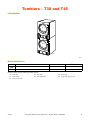
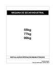
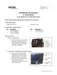
On-Premise
Laundry
Planning
Handbook
HIGH
TEMP
START
LOW
TEMP
MED
TEMP
NO
HEAT
25 C
1
SELECT
TEMP
1
SELECT
TEMP
2
INSERT
COIN
3
PUSH
START
HIGH
TEMP
START
LOW
TEMP
MED
TEMP
2
INSERT
COIN
3
NO
HEAT
PUSH
START
25 C
T477C
T477C
T30 and T45 Tumblers
Refer to Installation manual for full instructions.
4-08-43R5
August 2011
Table of
Contents
Tumblers – T30 and T45....................................................................
Introduction......................................................................................
Model Identification ..................................................................
Specifications and Dimensions ........................................................
Cabinet Dimensions...................................................................
Exhaust Outlet Locations...........................................................
Gas Connection Locations.........................................................
Electrical Connection Locations................................................
Steam Connection Locations .....................................................
Installation........................................................................................
Pre-Installation Inspection .........................................................
Exhaust Requirements .....................................................................
Layout ........................................................................................
Make-Up Air..............................................................................
Venting ......................................................................................
Individual Venting .....................................................................
Manifold Venting.......................................................................
Electrical Requirements for Gas and Steam Models .......................
Electrical Requirements for Electric Models ...................................
2
2
2
4
5
6
7
8
9
10
10
12
12
12
12
13
14
18
20
© Published by permission of the copyright owner.
All rights reserved. No part of the contents of this book may be reproduced or transmitted in any form or by any
means without the expressed written consent of the publisher.
1
© Copyright, Alliance Laundry Systems LLC – DO NOT COPY or TRANSMIT
4-08-43
Tumblers – T30 and T45
Introduction
HIGH
TEMP
START
LOW
TEMP
MED
TEMP
NO
HEAT
25 C
1
SELECT
TEMP
2
INSERT
COIN
3
PUSH
START
1
SELECT
TEMP
HIGH
TEMP
START
LOW
TEMP
MED
TEMP
2
INSERT
COIN
3
NO
HEAT
PUSH
START
25 C
T477C
T477C
Model Identification
Gas
T30
T45
Steam
IPD30STG2-ITT30L
IPD30STG2-ITT30N
IPD45STG2-ITT45L
IPD45STG2-ITT45N
IPD30STS2-ITT30S
Not Applicable
Electric
IPD30STE2-ITT30E
Not Applicable
Includes models with the following control suffixes:
3O – DX4 OPL
3V – DX4 vended
3X – DX4 prep for coin
4-08-43
EO – LED OPL
QT – dual digital timer
SD – single drop
SX – single drop, prep for coin
© Copyright, Alliance Laundry Systems LLC – DO NOT COPY or TRANSMIT
2
Tumblers – T30 and T45
1
TMB1974N
1
Serial Plate
Conversion Table
Multiply
3
By
To Obtain
Multiply
By
To Obtain
Btu
0.252
kCal
Pounds/sq. inch
0.06895
Btu
1055
Joules
Pounds/sq. inch
0.070
kg/sq. cm
Inch
25.4
Millimeters
Pounds (lbs.)
0.454
Kilograms
Inches W.C.
0.036
Pounds/sq. inch
Boiler Horsepower
33,479
Btu/hr.
Inches W.C.
0.249
kPa
Boiler Horsepower
34.5
lbs. steam/hr.
lb/inch2 (psi)
6.895
kPa
CFM
0.471
liters/second
ft3
28.32
Liters
kW
3414
Btu/hr.
© Copyright, Alliance Laundry Systems LLC – DO NOT COPY or TRANSMIT
Bars
4-08-43
Tumblers – T30 and T45
Specifications and Dimensions
Specifications
T30
T45
66 dBA
67 dBA
544
(247)
673
(305)
30 x 26
(762 x 660)
33 x 30
(838 x 762)
2 x 30
(2 x 13.6)
2 x 45
(2 x 20.5)
Drive Motor Horsepower**
1/4
1/2
Fan Motor Horsepower**
1/4
1/2
50 Hertz
340
(160)
N/A
60 Hertz
400
(189)
600
(283)
50 Hertz
0.8
(2.0)
N/A
60 Hertz
0.9
(2.3)
0.9
(2.3)
1/2 in. NPT
1/2 in. NPT
73,000
(21.4, 77)
95,000
(27.8, 100.2)
21 kW
N/A
3/4 in. NPT
N/A
3.2
(111,000)
N/A
Noise level measured during operation at operator
position of 3.3 feet (1 meter) in front of machine and
5.2 feet (1.6 meters) from floor.
Net Weight (approximate):
Pounds (kg)
Cylinder Size:
Inches (mm)
Cylinder Capacity (dry weight)
Pounds (kg)
Maximum Airflow per Pocket**:
C.F.M. (l/sec)
Maximum Static Back Pressure*:
Inches W.C. (mbar)
Gas Models
Gas Connection
Gas Burner Rating**:
Btu/hr (kW, Mj/hr)
Electric Models
Heating Element Rating**:
Steam Models
Steam Connection
Steam Coil Rating at 100 psig**:
Boiler Horsepower (Btu/hr)
(recommended operating pressure 80-100 psig)
* with both pockets running
** for each pocket
N/A = Not Applicable
4-08-43
© Copyright, Alliance Laundry Systems LLC – DO NOT COPY or TRANSMIT
4
Tumblers – T30 and T45
Cabinet Dimensions
J
A
B
C
D
E
F
H
G
I
TMB2332N
TMB2332N
Models
A
B
C
D
E
T30
28 in.
(711 mm)
49 in.
(1245 mm)
48.25 in.
(1226 mm)
11.4 in.
(290 mm)
10.7 in.
(272 mm)
T45
31.88 in.
(810 mm)
50.4 in.
(1280 mm)
49.3 in.
(1252 mm)
10.3 in.
(262 mm)
9.3 in.
(236 mm)
Models
F
G
H
I
J
T30
25.02 in.
(636 mm)
42.76 in.
(1086 mm)
27.38 in.
(695 mm)
31.5 in.
(800 mm)
76.25 in.
(1937 mm)
T45
29.37 in.
(746 mm)
48.62 in.
(1235 mm)
30.50 in.
(775 mm)
34.5 in.
(876 mm)
81.25 in.
(2063.75 mm)
NOTE: To meet ADA compliance, install a 4 inch
(102 mm) riser on T30 models only.
5
© Copyright, Alliance Laundry Systems LLC – DO NOT COPY or TRANSMIT
4-08-43
Tumblers – T30 and T45
Exhaust Outlet Locations
A
B
C
TMB1969N
TMB1969N
Models
4-08-43
Rear Exhaust
Diameter
A
B
C
T30
Elliptical
Fits 8 in. (203 mm)
36.54 in.
(928 mm)
4.25 in.
(108 mm)
62.42 in.
(1585 mm)
T45
Elliptical
Fits 10 in. (254 mm)
40.88 in.
(1038 mm)
4.75 in.
(121 mm)
66.00 in.
(1676 mm)
© Copyright, Alliance Laundry Systems LLC – DO NOT COPY or TRANSMIT
6
Tumblers – T30 and T45
Gas Connection Locations
C
B
1
A
TMB1970N
TMB1970N
1
1/2 in. NPT
Gas Connection
Models
T30
Non-CE and
Non-Australian
CE and
Australian
T45
7
A
75.20 in.
(1910 mm)
75.28 in.
(1912 mm)
78.75 in.
(2000 mm)
B
1.74 in.
(44 mm)
2.5 in.
(64 mm)
4.12 in.
(105 mm)
© Copyright, Alliance Laundry Systems LLC – DO NOT COPY or TRANSMIT
C
36.84 in.
(936 mm)
30.60 in.
(777 mm)
42.88 in.
(1089 mm)
4-08-43
Tumblers – T30 and T45
Electrical Connection Locations
E
B
A
D
C
GAS AND STEAM
ELECTRIC
TMB1971N
TMB1971N
Electric Service
Models
Gas and Steam Models
Electric Models
A
B
C
D
E
T30
59 in.
(1498 mm)
1.75 in.
(44 mm)
35.63 in.
(905 mm)
73.21 in.
(1859 mm)
2.28 in.
(58 mm)
T45
62.5 in.
(1588 mm)
1.75 in.
(44 mm)
N/A
N/A
N/A
N/A = Not Applicable
4-08-43
© Copyright, Alliance Laundry Systems LLC – DO NOT COPY or TRANSMIT
8
Tumblers – T30 and T45
Steam Connection Locations
C
D
A
B
A
B
TMB1972N
Models
Inlet
Outlet
A
C
B
D
T30
(Upper)
73.93 in.
(1877 mm)
6.29 in.
(160 mm)
62.71 in.
(1592 mm)
2.39 in.
(61 mm)
T30
(Lower)
36.35 in.
(923 mm)
6.29 in.
(160 mm)
25.13 in.
(638 mm)
2.39 in.
(61 mm)
NOTE: All connections use 3/4 inch NPT pipe.
9
© Copyright, Alliance Laundry Systems LLC – DO NOT COPY or TRANSMIT
4-08-43
Tumblers – T30 and T45
Installation
Pre-Installation Inspection
Upon delivery, visually inspect the crate, carton and
parts for any visible shipping damage. If the crate,
carton, or cover is damaged or signs of possible
damage are evident, have the carrier note the condition
on the shipping papers before the shipping receipt is
signed, or advise the carrier of the condition as soon as
it is discovered.
IMPORTANT: Warranty is void unless tumbler is
installed according to instructions in this manual.
Installation should comply with minimum
specifications and requirements detailed herein,
and with applicable local gas fitting regulations,
municipal building codes, water supply regulations,
electrical wiring regulations, and any other
relevant statutory regulations. Due to varied
requirements, applicable local codes should be
thoroughly understood and all pre-installation
work arranged for accordingly.
Remove the crate and protective cover as soon as
possible and check the items listed on the packing list.
Advise the carrier of any damaged or missing articles
as soon as possible. A written claim should be filed
with the carrier immediately if articles are damaged or
missing.
4-08-43
© Copyright, Alliance Laundry Systems LLC – DO NOT COPY or TRANSMIT
10
Tumblers – T30 and T45
WARNING
To reduce the risk of severe injury, clearance of tumble dryer cabinet from combustible
construction must conform to the minimum clearances.
W056R1
1
3
4
2
5
6
7
TMB2110N
TMB2110N
NOTE: Shaded areas indicate adjacent structure.
1
0.5 in. (13 mm) recommended between machines for removal or installation.
2
Allow 2 – 4 in. (51 – 102 mm) opening at top of machine to aid in removal or installation. A removable trim piece
may be used to conceal the opening; zero clearance allowed for trim.
3
4 in. (102 mm) Maximum Header Thickness
4
12 in. (305 mm) Minimum Clearance
5
24 in. (610 mm) Minimum, 36 in. (914 mm) recommended for maintenance purposes.
6
Provision for Make-Up Air: Minimum 1.5 square feet T30 models, minimum 2 square feet T45 models. Location
for reference only. May be anywhere behind tumbler.
7
0.25 in. (6 mm) recommended for removal or installation purposes, zero clearance allowed.
Figure 1
11
© Copyright, Alliance Laundry Systems LLC – DO NOT COPY or TRANSMIT
4-08-43
Tumblers – T30 and T45
Exhaust Requirements
Venting
WARNING
WARNING
A drying tumble dryer produces
combustible lint. To reduce the risk of
fire, the tumble dryer must be exhausted
to the outdoors.
W057R1
To reduce the risk of fire and
accumulation of combustible gases, DO
NOT exhaust tumble dryer air into a
window well, gas vent, chimney or
enclosed, unventilated area such as an
attic wall, ceiling, crawl space under a
building, or concealed space of a
building.
W059R1
Layout
Whenever possible, install tumblers along an outside
wall where duct length can be kept to a minimum, and
make-up air can be easily accessed. Elbows and long
vents tend to increase drying time. Construction must
not block the airflow at the rear of the tumbler. Doing
so would prevent adequate air supply to the tumbler’s
combustion chamber.
To reduce the risk of fire due to increased
static pressure, we do not recommend
installation of in-line secondary lint filters
or lint collectors. If secondary systems
are mandated, frequently clean the
system to assure safe operation.
W749
IMPORTANT: Installing in-line filters or lint
collectors will cause increased static pressure.
Failure to maintain the secondary lint system will
decrease tumbler efficiency and may void machine
warranty.
For maximum efficiency and minimum lint
accumulation, tumbler air must be exhausted to the
outdoors by the shortest possible route.
A tumbler is forced air exhausted and requires provisions
for make-up air to replace air exhausted by the tumbler.
Proper sized exhaust ducts are essential for proper
operation. All elbows should be sweep type. Exhaust
ducts must be assembled so the interior surfaces are
smooth, so the joints do not permit the accumulation
of lint. DO NOT use plastic or thin foil ducts – rigid
metal ducts are recommended. Use exhaust ducts
made of sheet metal or other noncombustible material.
DO NOT use sheet metal screws or fasteners on
exhaust pipe joints which extend into the duct and
catch lint. Use of duct tape or pop-rivets on all seams
and joints is recommended, if allowed by local code.
IMPORTANT: Do not obstruct the flow of
combustion and ventilation air.
Verify that old ducts are thoroughly cleaned out before
installing new tumbler(s).
Make-Up Air
Make-up air openings should be as close to the
tumbler(s) as possible.
The required make-up air opening to the outside for
each tumbler (includes both pockets) is:
220 square inches (1418 sq. cm) for T30 models
288 square inches (1856 sq. cm) for T45 models
Make-up air openings with louvers will restrict
airflow. The opening must be increased to compensate
for area taken up by louvers.
Make-up air openings for a room containing
tumbler(s) and/or gas fired hot water heater or other
gravity vented appliances must be increased
sufficiently to prevent downdrafts in any of the vents
when all tumblers are in operation. Do not locate
gravity vented appliances in the same room as
tumblers. If it is necessary to duct make-up air to the
tumbler(s), increase the area of the ductwork by 25%
to compensate for any restriction in air movement.
4-08-43
WARNING
Improperly sized or assembled ductwork
causes excess back pressure which
results in slow drying, lint collecting in
the duct, lint blowing back into the room,
and increased fire hazard.
W355
NOTE: Exhaust ducts must be constructed of sheet
metal or other noncombustible material. Such
ducts must be equivalent in strength and corrosion
resistance to ducts made of galvanized sheet steel
not less than 0.0195 inches (0.495 mm) thick. Local
codes may require additional thickness.
Where the exhaust duct pierces a combustible wall or
ceiling the opening must be sized per local codes. The
space around the duct may be sealed with
non-combustible material. Refer to Figure 2.
© Copyright, Alliance Laundry Systems LLC – DO NOT COPY or TRANSMIT
12
Tumblers – T30 and T45
IMPORTANT: For best performance provide an
individual exhaust duct for each tumbler. Do not
install a hot water heater in a room containing
tumblers. It is better to have the water heater in a
separate room with a separate air inlet.
Individual Venting
For maximum efficiency and performance, it is preferred
to exhaust tumbler(s) individually to the outdoors.
IMPORTANT: At no point may the cross sectional
area of installed venting be less than the cross
sectional area of the exhaust outlet of the tumbler.
The exhaust duct must be designed so the static back
pressure measured 12 inches (305 mm) from the
exhaust outlet does not exceed the maximum
allowable pressure specified on the installation sticker
on the rear of the tumbler.
NOTE: Static back pressure must be measured
with both pockets running.
The maximum allowable length venting of the same
diameter as the exhaust thimble is 14 feet (4.3 m) and
two 90° elbows or equivalent. If the equivalent length
of a duct required for an installation exceeds the maximum
allowable equivalent length, the diameter of a round duct
must be increased by 10% for each additional 20 feet
(6.1 m). Cross section area of a rectangular duct must
be increased by 20% for each additional 20 feet (6.1 m).
Refer to Table 1 to determine equivalent venting.
Duct
Diameter
10 in. (254 mm)
12 in. (305 mm)
14 in. (355.6 mm)
16 in. (406.4 mm)
18 in. (457.2 mm)
Equivalent Length of Rigid
Straight Duct
One 90° elbow = 11.6 ft. (3.5 m)
One 90° elbow = 14 ft. (4.3 m)
One 90° elbow = 16 ft. (4.9 m)
One 90° elbow = 18.7 ft. (5.7 m)
One 90° elbow = 21 ft. (6.4 m)
Equivalent Length (feet) = 1.17 x Duct Diameter (inches)
Table 1
Example: A 12 inch (305 mm) diameter duct’s
equivalent length of 14 feet (4.3 m) of duct and two
90° elbows is:
Equivalent Length = 14 feet + (2) 90° elbows
= 14 feet + 14 feet + 14 feet
= 42 feet (12.8 m)
With the tumbler in operation, and both pockets
running, airflow at any point in the duct should be at
least 1200 feet per minute (366 meters per meter) to
ensure that lint remains airborne. If 1200 feet per
minute cannot be maintained, schedule monthly
inspections and cleaning of the ductwork.
NOTE: The maximum length of a flexible metal
duct must not exceed 2.4 m (7.87 ft.) as required to
meet UL2158, clause 7.3.2A.
13
© Copyright, Alliance Laundry Systems LLC – DO NOT COPY or TRANSMIT
4-08-43
Tumblers – T30 and T45
3
4
2
1
5
TMB2103N
TMB2103N
1
2
3
4
5
Removable strip of panel in framing wall to permit removal of tumbler from framing wall
Partition or bulkhead
Minimum distance between exhaust opening and roof, ground or other obstruction: 36 in. (914 mm)
2 in. (51 mm) minimum clearance on both sides of duct
Exhaust airflow – maximum length of duct: 14 ft. (4.3 m)
Figure 2
NOTE: Do not install wire mesh or screen in
exhaust duct opening to avoid lint build-up or
impacting proper discharge of air from tumblers.
NOTE: Where exhaust duct pierces a combustible
wall or ceiling, the opening must be sized per local
codes.
NOTE: Inside of duct must be smooth. Do not use
sheet metal screws to join sections.
Consult your local building code for regulations which
may also apply.
4-08-43
Manifold Venting
While it is preferable to exhaust tumblers individually
to the outdoors, a main collector duct may be used if it
is sized according to Figure 4 or Figure 5. This
illustration indicates minimum diameters, and should
be increased if the collector length exceeds 14 feet (4.3
m) and two 90° elbows. The diameter of a round duct
must be increased by 10% for each additional 20 feet
(6.1 m). Cross sectional area of a rectangular or square
duct must be increased 20% for each additional 20 feet
(6.1 m). Refer to Table 2 or Table 3 to determine
equivalent ducting sizing. The collector duct may be
rectangular or square in cross section, as long as the
area is not reduced. Provisions MUST be made for lint
removal and cleaning of the collector duct.
© Copyright, Alliance Laundry Systems LLC – DO NOT COPY or TRANSMIT
14
Tumblers – T30 and T45
The vent collector system must be designed so the
static back pressure measured 12 inches (305 mm)
from the exhaust outlet does not exceed the maximum
allowable pressure specified on the installation sticker
on the rear of tumbler. Static back pressure must be
measured with all tumblers vented into the collector
operating.
With the tumbler in operation, and both pockets
running, airflow at any point in the duct should be at
least 1200 feet per minute (366 meters per meter) to
ensure that lint remains airborne. If 1200 feet per
minute cannot be maintained, schedule monthly
inspections and cleaning of the ductwork.
NOTE: Never connect a tumbler duct at a 90°
angle to the collector duct. Refer to Figure 3. Doing
so will cause excessive back pressure, resulting in
poor performance. Never connect two tumbler
exhaust ducts directly across from each other at the
point of entry to the collector duct.
T438i
T438I
Figure 3
15
© Copyright, Alliance Laundry Systems LLC – DO NOT COPY or TRANSMIT
4-08-43
Tumblers – T30 and T45
1
2
L
K
3
J
I
H
G
F
E
D
C
B
A
ONE MANIFOLD ASSEMBLY
TMB2019N
1
NOTE: Where the exhaust duct pierces a
combustible wall or ceiling, the opening
MUST be sized per local codes.
2
3
Outlet Duct Diameter
45° Typical
Figure 4
Duct
Station
T30
T45
8 in. (203 mm) Duct
10 in. (254 mm) Duct
A
8 in. (203 mm)
10 in. (254 mm)
B
12 in. (305 mm)
15 in. (381 mm)
C
15 in. (381 mm)
18 in. (457 mm)
D
17 in. (432 mm)
21 in. (533 mm)
E
19 in. (483 mm)
24 in. (610 mm)
F
21 in. (533 mm)
26 in. (660 mm)
G
23 in. (584 mm)
28 in. (711 mm)
H
24 in. (610 mm)
30 in. (762 mm)
I
26 in. (660 mm)
32 in. (813 mm)
J
27 in. (686 mm)
33 in. (838 mm)
K
28 in. (711 mm)
35 in. (889 mm)
L
30 in. (762 mm)
36 in. (914 mm)
Table 2
4-08-43
© Copyright, Alliance Laundry Systems LLC – DO NOT COPY or TRANSMIT
16
Tumblers – T30 and T45
1
2
I
J
K
L
L
K
J
I
CONTINUE
TO A
CONTINUE
TO A
TWO MANIFOLD ASSEMBLIES
3
TMB2018N
1
NOTE: Where the exhaust duct pierces a
combustible wall or ceiling, the opening
MUST be sized per local codes.
2
3
Outlet Duct Diameter
45° Typical
Figure 5
Duct
Station
T30
T45
8 in. (203 mm) Duct
10 in. (254 mm) Duct
A
12 in. (305 mm)
15 in. (381 mm)
B
17 in. (432 mm)
22 in. (559 mm)
C
22 in. (559 mm)
26 in. (660 mm)
D
25 in. (635 mm)
30 in. (762 mm)
E
27 in. (686 mm)
34 in. (864 mm)
F
30 in. (762 mm)
37 in. (940 mm)
G
33 in. (838 mm)
40 in. (1016 mm)
H
34 in. (864 mm)
43 in. (1092 mm)
I
37 in. (940 mm)
46 in. (1168 mm)
J
39 in. (991 mm)
47 in. (1194 mm)
K
40 in. (1016 mm)
50 in. (1270 mm)
L
43 in. (1092 mm)
51 in. (1295 mm)
Table 3
17
© Copyright, Alliance Laundry Systems LLC – DO NOT COPY or TRANSMIT
4-08-43
Tumblers – T30 and T45
Electrical Requirements for Gas and
Steam Models
NOTE: Electrical specifications below are subject
to change without notice. Always refer to product
serial plate for most current specifications of
product being installed.
Refer to Table 4 and Table 5.
NOTE: Use copper conductors only.
NOTE: Minimum wire sizes are obtained from
Canadian Electrical Code for 75°C Conductors
and are intended for use as a guideline only.
Electrical connections should be made only by a
qualified electrical contractor in accordance with
all applicable local and national requirements.
NOTE: 3 Phase Only – Each tumbler must be
connected to its own individual branch circuit
breaker, not fuses, to avoid the possibility of “single
phasing” and causing premature failure of the
motor(s).
For T30 Gas and Steam Models
(For Total Machine):
Current
(Amps)
Recommended
Fuse or
Breaker Rating
(Amps)
Breaker
Poles
Recommended
Minimum
Conductor Size
Serial Plate Voltage
Terminal Block
Connections
Required
120V/60 Hz/1ph
L1, Neutral,
and ground
16.0
20
1
12 (3.31)
208-240V/60Hz/1ph
L1, L2, Neutral,
and ground
8.0
10
2
14 (2.08)
100V/60Hz/1ph
L1, Neutral,
and ground
22.0
30
1
10 (5.26)
200-220V/60Hz/1ph
L1, Neutral,
and ground
11.6
15
1
14 (2.08)
100V/50Hz/1ph
L1, Neutral,
and ground
24.2
35
1
8 (8.37)
200V/50Hz/1ph
L1, Neutral,
and ground
15.0
20
1
12 (3.31)
230-240V/50Hz/1ph
L1, Neutral,
and ground
15.0
20
1
12 (3.31)
200-208V/60Hz/3ph
L1, L2, L3,
and ground
6.4
10*
3
14 (2.08)
240V/60Hz/3ph
L1, L2, L3,
and ground
6.4
10*
3
14 (2.08)
200V/50Hz/3ph
L1, L2, L3,
and ground
5.8
10*
3
14 (2.08)
230-240V/50Hz/3ph
L1, L2, L3,
and ground
7.0
10*
3
14 (2.08)
380V/50 or 60Hz/3ph
L1, L2, L3,
and ground
3.0
10*
3
14 (2.08)
400-415V/50Hz/3ph
L1, L2, L3,
and ground
3.2
10*
3
14 (2.08)
460-480V/60Hz/3ph
L1, L2, L3,
and ground
3.3
10*
3
14 (2.08)
(AWG [mm2])
* 3 Phase machines should not have fuses, breakers only.
Table 4
4-08-43
© Copyright, Alliance Laundry Systems LLC – DO NOT COPY or TRANSMIT
18
Tumblers – T30 and T45
For T45 Gas Models (For Total Machine):
Recommended
Recommended Fuse
Minimum
Current
Breaker
or Breaker Rating
Conductor Size
(Amps)
Poles
(AWG [mm2])
(Amps)
Serial Plate
Voltage
Terminal Block
Connections
Required
208–240V/60Hz/1ph
L1, L2, Neutral and ground
12.0
15
2
14 (2.08)
200–208V/60Hz/3ph
L1, L2, L3 and ground
9.6
15
3
14 (2.08)
240V/60Hz/3ph
L1, L2, L3 and ground
9.6
15
3
14 (2.08)
200V/50Hz/1ph
L1, Neutral and ground
11.2
15
1
14 (2.08)
230-240V/50Hz/1ph
L1, Neutral and ground
10.8
15
1
14 (2.08)
Table 5
19
© Copyright, Alliance Laundry Systems LLC – DO NOT COPY or TRANSMIT
4-08-43
Tumblers – T30 and T45
Electrical Requirements for Electric
Models
Refer to Table 6.
NOTE: Electrical specifications below are subject
to change without notice. Always refer to product
serial plate for most current specifications of
product being installed.
NOTE: Connect to individual branch circuit.
NOTE: Minimum wire sizes are obtained from
Canadian Electrical Code for 75°C Conductors
and are intended for use as a guideline only.
Electrical connections should be made only by a
qualified electrical contractor in accordance with
all applicable local and national requirements.
NOTE: 3 Phase Only – Each tumbler must be
connected to its own individual branch circuit
breaker, not fuses, to avoid the possibility of “single
phasing” and causing premature failure of the
motor(s).
For 21 kW T30 Electric Models:
Serial Plate
Voltage
Terminal Block
Connections
Required
Current
(Amps)
Recommended
Breaker Rating
(Amps)
Breaker
Poles
Recommended
Minimum
Conductor Size
200-208V/60Hz/3ph*
L1, L2, L3,
and ground
62**
80
3
4 (21.2)
200V/50Hz/3ph*
L1, L2, L3,
and ground
60**
80
3
4 (21.2)
230-240V/50Hz/3ph*
L1, L2, L3,
and ground
55**
70
3
4 (21.2)
240V/60Hz/3ph*
L1, L2, L3,
and ground
54**
70
3
4 (21.2)
380V/50 or 60Hz/3ph*
L1, L2, L3,
and ground
33**
45
3
8 (8.37)
400-415V/50Hz/3ph*
L1, L2, L3,
and ground
31**
40
3
8 (8.37)
460-480V/60Hz/3ph*
L1, L2, L3,
and ground
27**
35
3
8 (8.37)
(AWG [mm2])
* These serial plate voltages are only options available on the T30 electric models. Current (Amp) is for one pocket only.
** Per heater on T30 electric models, each has two heaters.
Table 6
4-08-43
© Copyright, Alliance Laundry Systems LLC – DO NOT COPY or TRANSMIT
20