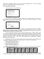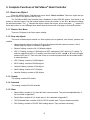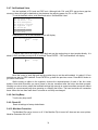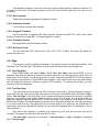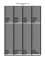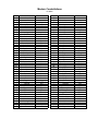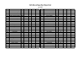
1
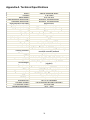
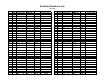
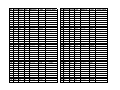
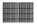
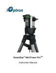
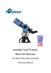
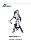
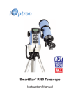
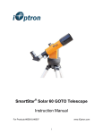
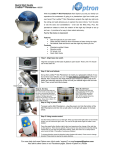
SmartStar® iEQ75-GTTM
Instruction Manual
Table of Content
Table of Content ................................................................................................................................................. 2
1. iEQ75-GTTM Overview .................................................................................................................................. 4
2. iEQ75-GTTM Assembly .................................................................................................................................. 5
2.1. Parts List.................................................................................................................................................. 5
2.2. Assembly terms ....................................................................................................................................... 7
2.3. iEQ75-GTTM Ports................................................................................................................................... 8
2.4. Introduction ............................................................................................................................................. 8
2.5. iEQ75-GT Assembly ............................................................................................................................... 9
3. GoToNova® 8406 Hand Controller .............................................................................................................. 16
3.1. Key Description..................................................................................................................................... 16
3.2. The LCD Screen .................................................................................................................................... 17
4. Getting Started.............................................................................................................................................. 18
4.1. Setup the Mount and Polar Alignment .................................................................................................. 18
4.2. Manual Operation of the Mount ............................................................................................................ 18
4.3. Setting Up the Hand Controller............................................................................................................. 18
4.3.1. Set Up Local Time.......................................................................................................................... 18
4.3.2. Set Up Observation Site ................................................................................................................. 19
4.3.3. Set N/S Hemisphere ....................................................................................................................... 20
4.3.4. Initial Star Alignment ..................................................................................................................... 20
4.3.5. Go to the Moon............................................................................................................................... 20
4.4. Turn Off the Mount ............................................................................................................................... 21
5. Complete Functions of GoToNova® Hand Controller ................................................................................. 22
5.1. Slew to an Object................................................................................................................................... 22
5.1.1. Planets, Sun, Moon......................................................................................................................... 22
5.1.2. Deep sky objects............................................................................................................................. 22
5.1.3. Comets............................................................................................................................................ 22
5.1.4. Asteroids......................................................................................................................................... 22
5.1.5. Stars: ............................................................................................................................................... 22
5.1.6. Constellations ................................................................................................................................. 23
5.1.7. Enter R.A. DEC.............................................................................................................................. 23
5.2. Sync to Target........................................................................................................................................ 23
5.3. Electric Focuser ..................................................................................................................................... 23
5.4. Set Up Controller................................................................................................................................... 23
5.4.1. Set Up Local Time.......................................................................................................................... 23
5.4.2. Set Up Observation Site ................................................................................................................. 23
5.4.3. Set N/S Hemisphere ....................................................................................................................... 23
5.4.4. Set Display Contrast ....................................................................................................................... 23
5.4.5. Set Eyepiece Light.......................................................................................................................... 23
5.4.6. Set Backlight .................................................................................................................................. 23
5.4.7. Set Backlash Value......................................................................................................................... 24
5.4.8. Set Key Beep .................................................................................................................................. 24
5.4.9. Reset All ......................................................................................................................................... 24
5.4.10. Meridian Protection ...................................................................................................................... 24
5.4.11. Set Language ................................................................................................................................ 25
5.4.12. Heating Controller ........................................................................................................................ 25
5.4.13. Upgrade Firmware........................................................................................................................ 25
5.4.14. Firmware Version......................................................................................................................... 25
5.4.15. Set Speed Limit ............................................................................................................................ 25
2
5.5. Align ...................................................................................................................................................... 25
5.5.1. One-Star Align................................................................................................................................ 25
5.5.2. Two-Star Align............................................................................................................................... 25
5.5.3. Dis R.A axis error........................................................................................................................... 26
5.5.4. Polaris Position............................................................................................................................... 26
5.6. PEC Option............................................................................................................................................ 26
5.7. Set Up Tracking..................................................................................................................................... 26
5.8. Auto Guide ............................................................................................................................................ 26
5.8.1. Set Guider Rate............................................................................................................................... 26
5.8.2. Set Guider Direction....................................................................................................................... 26
5.9. Park Scope ............................................................................................................................................. 27
5.9.1. Park Scope ...................................................................................................................................... 27
5.9.2. Set Park Position............................................................................................................................. 27
5.10. To Zero Position .................................................................................................................................. 27
6. Maintenance and Servicing .......................................................................................................................... 28
6.1. Maintenance .......................................................................................................................................... 28
6.2. iOptron Customer Service ..................................................................................................................... 28
6.3. Product End of Life Disposal Instructions ............................................................................................ 28
6.4. Battery Replacement and Disposal Instructions.................................................................................... 28
Appendix A. Technical Specifications ............................................................................................................. 29
Appendix B. GoToNova® 8406 HC MENU STRUCTURE ............................................................................ 30
Appendix C. Firmware Upgrade ...................................................................................................................... 32
Appendix D. Use a PC to Control an iEQ75-GT Mount.................................................................................. 33
Appendix E. GoToNova® Star List .................................................................................................................. 34
IOPTRON TWO YEAR TELESCOPE, MOUNT, AND CONTROLLER WARRANTY............................ 41
WARNING!
NEVER USE A TELESCOPE TO LOOK AT THE SUN WITHOUT A PROPER FILTER!
Looking at or near the Sun will cause instant and irreversible damage to your eye. Children
should always have adult supervision while observing.
3
1. iEQ75-GTTM Overview
The iEQ75-GT™ is a one-of-a-kind premium CNC-machined astro-imaging mount from iOptron. The
iEQ75-GT™ offers the next generation GoTo technology from iOptron. With a Renishaw high resolution
encoder-enabled double closed-loop tracking, the system is able to tracking the target with a tracking error
less that ±1 arcsec. The iEQ75-GT™ has a payload of 75 lb (34 kg) and includes a calibrated dark field
illumination polar scope. Its unique base design makes it easy for just one person to carry to location.
Features:
•
•
•
•
•
•
•
•
•
•
•
•
•
•
•
•
•
•
Premium CNC-machined astrophotography mount suited for advanced imaging
Heavy duty German equatorial mount
Maximum payload: 75 lb (34 kg) (excluding counterweight)
Mount weight: 52 lb (23.6 kg)
Angular contact ball bearings for R.A and DEC axles, as well as worm gear shafts
Precision DC servo motor-driven and double closed-loop tracking with Renishaw high resolution
encoder feedback
32-bit ARM system for ultra-accurate tracking with temperature-compensated crystal oscillator
(TCXO)
Maximum tracking error: ± 1 arc second
Advanced GOTONOVA® technology for accurate GOTO and tracking
Built-in 32-channel Global Positioning System (GPS)
Integrated ST-4 autoguiding port capable of reverse guiding with auto-protection
Hand Box (HBX) port for hand controller connection
iOptron port for electronic focuser, laser pointer, planetary dome control
RS232 port for firmware upgrading and computer control via ASCOM platform
Calibrated polar scope with dark-field illumination and easy polar alignment procedure, allowing for
fast and accurate polar alignment
Heated hand controller for low temperature operation as low as -20ºC
Comes standard with:
o a mounting plate for Vixen or Losmandy-D saddles
o a Vixen dovetail saddle
o stainless steel counterweight shaft with safety lock
o 2 x 16.5 lb (7.5 kg) stainless steel counterweights
o 12V DC car plug adaptor
o USB cable
o RS232 Cable
Optional tripod or pier
4
2. iEQ75-GTTM Assembly
2.1. Parts List1
The parts comes with the iEQ75-GTTM order include an EQ mount (Figure 1), one mounting plate
(Figure 2), 2 counterweights and an CW shaft (Figure 1). Other parts are, as shown in Figure 4, an 8406
hand controller, coiled hand controller cable, a Vixen dovetail saddle, R.A. and DEC cables, a dark field
illuminating LED with cable, a 12V DC adapter cable with car lighter plug, a USB Cable, a RS232 cable,
GPS antenna, a hex key set, 4 base mounting screws, and 8 M6X20 hex head screws
Figure 1. iEQ75-GT mount
Figure 2. Mounting plate
1
Actual contents may vary from time to time.
5
Figure 3. Counterweights and CW shaft
Figure 4. Included accessories
6
2.2. Assembly terms
DEC Unit
Mounting plate
DEC DIN cable
Polar Axis Cover
Main control box
R.A. Unit
Polar Scope Cover
CW Shaft
Lat. Locking Screw
Counterweight (CW)
Azi. Adjust. Knob
8406 Hand Controller
CW Safety Screw
Azi. Locking Screw
Tripod Head
Alignment Peg
Tripod Spreader
Tripod Lock
Tripod Leg
Leg Lock Screw
Figure 5. iEQ75-GT assembly terms (mount and optional tripod)
7
2.3. iEQ75-GTTM Ports
Figure 6. Ports on iEQ75-GTTM control box
•
•
•
•
•
•
•
•
•
R.A. and DEC motor: For connecting to R.A. and DEC driver unit
Power: Power switch
DC 12V: 12 volts DC power plug (center positive)
HBX (Hand Box): For connecting to the 8406 Hand Controller
iOptron port: For connecting to other iOptron accessories, such as an electronic focuser, a laser
pointer, or a planetary dome control
RS232: Series port for ASCOM control and main board firmware upgrade
Autoguide: Autoguiding port for ST-4 compatible guiding cameras
GPS: GPS antenna connection
Reticle: Power supply for the Polar Scope dark field illumination LED
2.4. Introduction
You have just purchased a telescope mount that is capable of taking you to a new level of
astronomy. No matter which telescope or optical tube assembly (OTA) you select to install on the mount,
the overall performance will be greatly enhanced. In order for you to get the optimum performance from the
mount and OTA combination, you must assemble and adjust the mount correctly. The following
fundamentals of telescope mounts are included to help you understand the big picture before you get into
the specific details of the iEQ75-GT mount.
Telescope mounts are either equatorial mounts or altitude-azimuth (Alt-Az) mounts. Both types of
mounts rotate the OTA around two perpendicular axes to point to a desired object in the night sky. An
equatorial mount has the right ascension (R.A.) axis aligned with the celestial North Pole (CNP), or celestial
South Pole (CSP), to provide rotation matching the celestial sphere rotation around the Earth and the
declination axis (DEC) to provide elevation relative to the celestial equator. Since all celestial objects
appear to rotate around the CNP, the R.A. axis allows the OTA to rotate with the celestial sphere and
provide accurate tracking for visual observations and astrophotography. R.A. is the celestial equivalent of
longitude. Like longitude, R.A. measures an angle that increases toward the East as measured from a zero
reference point on the celestial equator. An Alt-Az mount has a horizontal axis to provide vertical (altitude)
OTA movement from the local horizon and a vertical axis to provide horizontal (azimuth) OTA movement,
similar to compass headings. An Alt-Az mount can provide tracking that is good enough for visual observing
8
and short exposure photos, but not good enough for serious astrophotography. Alt-Az mounts require star
alignments for the OTA to track stars and they do not have adjustment components on the mount.
Equatorial mounts require alignment of the mount components as well as star alignments for accurate OTA
tracking.
In order to provide the required Polar Axis alignment, equatorial mounts use a combination of both
mount types described above. The adjustable part of the mount moves in the Alt-Az mode in order to align
the R.A. axis, also known as the mount’s Polar Axis, with the CNP. These Polar Axis adjustments do not
involve any rotations of the OTA about the R.A. or DEC axes and can be performed without the OTA
installed. The first step is to make an approximate azimuth alignment of the Polar Axis by aligning the
specified tripod leg or reference point toward True North using a compass for reference (you must allow for
the variation between True and Magnetic North at your location). Precise horizontal alignment of the Polar
Axis is accomplished with azimuth adjustments on the mount. The second step is to adjust the Polar Axis
vertically (altitude) above the North horizon by setting the observer’s latitude on the provided latitude scale.
This procedure is based on the fundamental geometry of the Earth’s coordinate system in conjunction with
the concept of the celestial sphere. You can verify this by visualizing yourself at the North Pole (latitude
N90°) and Polaris will be 90° from the horizon, or directly overhead. These steps will place the Polar Axis
very close to the CNP. Both of the above adjustments can be enhanced by the use of an opening along the
R.A. axis that allows direct viewing of the North Star and the use of a polar scope to view through this
opening. If you are going to get the most out of your equatorial mount it is essential to understand the
concept of the Polar Axis and how the equatorial mount helps you establish and maintain a true Polar Axis
alignment. Now, you are ready to perform star alignments using the equatorial mount’s electronic controller
and enjoy the night sky.
The iEQ75-GT is a next-generation equatorial mount that provides the precision alignment
capabilities required for today’s complete astronomy solution. The following sections of this manual provide
the detailed steps required to successfully set up and operate the iEQ75-GT.
2.5. iEQ75-GT Assembly
NOTE: The iEQ75-GT is a precision astronomical instrument. It is highly recommended that you
read the entire manual and become familiar with the nomenclature and function of all components
before starting the assembly.
STEP 1. Setup Tripod
Expand the tripod legs and install the Tripod Support using the Tripod Lock as shown in Figure 7.
Tightening the Tripod Lock will expand the tripod legs fully and provide maximum support for the mount and
the Optical Tube Assembly (OTA). Adjust the tripod height by unlocking the tripod Leg Lock Screws, sliding
the lower tripod leg to the desired length, and relocking the tripod Leg Lock Screws. It is recommended that
you extend the legs fully during the first assembly and modify the length as required in subsequent
adjustments. After the legs are adjusted and locked, stand the tripod with the Alignment Peg facing True
South. If you are located in the southern hemisphere, face the Alignment Peg True North.
STEP 2. Attach the iEQ75-GT Mount
Locate the Azimuth Adjustment Knobs and retract them to allow enough clearance for the mount to
fit on the tripod head. Unscrew the four (4) Azimuth Locking Screws shown in Figure 8. Place the mount
onto the Tripod Head with the alignment notch on top of the Alignment Peg. Place the four (4) Azimuth
Locking Screws back and tighten the screws. Level the tripod base by adjusting the individual legs. You
need a level to check leveling.
9
Figure 8. Attaching the mount
Figure 7. Tripod
STEP 3. Connect Cables
Figure 9. Cable connections
There are two DIN 6 cables that have C091 connectors on both ends of the cable. Insert one end of
the DIN 6 cable into the R.A. socket on the control box, and the other end into the socket located on R.A.
driver unit, as shown in Figure 9. Secure both ends of the DIN 6 cable. Connect another DIN 6 cable
between the DEC socket on the control box and the DEC socket on DEC driver unit. Attach the DIN 6 end
of a DIN-RJ-11 cable into the HBX socket on the control box and the RJ-11 end into the hand controller.
Connect the GPS antenna into the GPS socket on the control box. Plug the 12V DC power supply (center
positive) into the Power socket on the control box. The back light of the hand controller will illuminate when
the power switch is turned on.
STEP 4. Set the Location Latitude
This step requires you to know the latitude of your current location. This can be found from your
8406 hand controller after the embedded GPS receives the signal from the satellites. It also can be easily
found on the Internet, with your GPS navigator or a GPS capable cell phone. You will have to change this
latitude setting every time you significantly change your night sky viewing location.
10
Lat. Adjust. Lever
Azi. Adjust. Knob
Latitude Adjustment Knob
Figure 10. Adjust latitude
Unscrew the Latitude Adjustment Lever from the Latitude Adjustment Knob as shown in Figure 10.
Turn the Latitude Adjustment Knob to set your current latitude, using the Latitude Adjustment Lever for a
fine adjustment, if needed. At this point, with the mount level and pointed North, and the latitude set, the
Polar Axis (R.A. axis) should be pointing very close to the NCP and Polaris.
CAUTION: For safety reasons, always adjust the latitude without an OTA and/or counterweights
installed. Also, it is much easier to make this precise adjustment without a load on the axis being
adjusted.
STEP 5. Polar Alignment
As explained in the introduction, an equatorial mount must have an accurate polar axis alignment in
order to track properly. With the iOptron innovative Polar Scope and Quick Polar Alignment procedure, you
can do a fast and accurate polar axis alignment.
Figure 11. Polar Scope Dial
As indicated in Figure 11, the Polar Scope Dial has been divided into 12 hours along the angular
direction with half-hour tics. There are 2 groups, 6 concentric circles marked from 36’ to 44’ and 60’ to 70’,
respectively. The 36’ to 44’ concentric circles are used for polar alignment in northern hemisphere using
Polaris. While the 60’ to 70’ circles are used for polar alignment in southern hemisphere using Sigma
Octantis.
Polar axis adjustments
Whenever polar axis adjustments are required, loosen the four Azimuth Locking Screws and adjust
the Azimuth Adjustment Knobs to do a fine adjustment of the mount in the azimuth direction. Tighten
11
the locking screws to secure the mount. Loosen four Latitude Locking Screws on the side of the
mount, turning the Latitude Adjustment Knob to adjust the latitude (altitude). Use the Lever for a fine
latitude adjustment. Re-tighten the lock screws.
Initializing the polar scope
During initial setup of the iEQ mount, it is likely that the viewing hole on the DEC axis of the polar
scope may be blocked by the DEC axle. The Polar Scope Dial in the polar scope should be set at
the normal clock position with 12 o’clock located at the top, as shown in Figure 11. Before doing the
Quick Polar Axis Alignment, complete the following steps:
(1) Take off both the Polar Axis Cover and the Polar Scope Cover from the mount.
(2) Thread the dark field illuminating LED end into the threaded hole and plug the other end into the
Reticle socket located on the control box (Figure 12). The illumination intensity can be adjusted
using the hand controller (HC) via the “Set Eyepiece Light” function under the “Set Up
Controller” menu.
(3) Use the UP or DOWN button to turn the DEC axle if it blocks the Polar Scope view, press
number buttons to change the slew speed.
(4) If the 12 o’clock of the Polar Scope dial is not at the top, as shown in Figure 11, rotate it using
HC’s LEFT or RIGHT button.
Figure 12. Connect the illumination LED to Polar Scope
NOTE: Do not disassemble the Polar Scope to rotate it. It is adjusted at the factory and can
be misaligned if you disassemble it. A good Polar alignment is the basis for good GOTO and
tracking performance.
Quick polar axis alignment
(1) Turn on the mount power by pressing the On/Off switch on the R.A. unit. After “GPS OK” is
shown in the upper right corner of the HC, the LCD will display the Polaris Position as shown in
Figure 13 (a). If you are practicing inside or when there is no GPS signal, you can view this
chart by pressing the MENU button, then select “Align” and “Polaris Position”. For example,
on May 30, 2010, 20:00:00 in Boston, US (Lat N42º30’32” and Long W71º08’50”), 300 min
behind UT, the Polaris Position is 1hr 26.8m and r= 41.5m, as shown in Figure 13 (a).
(2) Look through the polar scope; make sure the polar scope is not blocked by the DEC axle. The
12 o’clock indicator of the Polar Scope Dial must be positioned on top.
(3) Follow the Polar axis adjustment procedure (not the hand controller) to adjust the mount in
altitude (latitude) and azimuth (heading) direction and place Polaris in the same position on the
12
Polar Scope Dial as indicated on the HC LCD. In this case, the Polaris will be located at a radius
of 41.5’ and an angle of 1 hour 26.8 minute, as shown in Figure 13 (b).
(a)
(b)
Figure 13. Polaris displayed on 8406 hand controller (a) and Polaris located on Polar scope dial
STEP 4. Attach Dovetail Adapter
Install the Mounting Plate onto the iEQ75-GT mount. Both Vixen (included) and Losmandy-D
dovetail saddles can be used. The mounting-hole distribution on the Mount Plate is shown in Figure 14.
Figure 14. The mounting-hole distribution on the Mount Plate
STEP 7. Install Counterweight(s)
iEQ75-GT comes with two 16.5 lb (7.5 kg) stainless steel counterweights (CWs). Use one or both
CWs as required for your particular OTA. Additional CW(s) may be needed to balance a heavier OTA
(Optional CWs are available from iOptron).
CSUTION: The mount must be at the zero position when the counterweights are being installed. The
Zero Position is the position with the CW shaft pointing toward the ground, as shown in Figure 15. Use your
hand controller to move the mount.
13
Figure 15. Zero position
Remove the CW Safety Screw on the end of the CW shaft. Loosen the CW Locking Screw on the
side of the CW (there is a CW pin inside) and slide the CW into the shaft. Tighten the CW Locking Screw to
hold the CW in place. Tighten the CW Safety Screw.
CAUTION: For safety reasons, the CW Safety Screw must be installed and tightened to prevent the
CW from dropping off the end of the CW shaft. This can cause serious personal injury.
STEP 8. Attach and Balance an OTA on the Mount
After attaching an OTA and accessories to the mount, the mount must be balanced to ensure
minimum stress on the mount’s gears and motors. There are no clutch screws on either R.A. or DEC axes.
The balancing is performed using iOptron Electronic Balance technology.
Set the mount at Zero Position first. If it is not, turn the mount on, press the arrow key on the hand
controller to adjust the mount position. Press number key on the hand controller to select appropriate
speed. After the Zero Position is adjusted, turn the power off.
Balance the mount in R.A. and DEC axes
When the mount is rest at Zero Position, turn the mount power on. Press the MENU button, scroll
down to “Balance Test”, and press ENTER. The mount will start to slew and stop at the balance test
position, as shown in Figure 16.
Figure 16. Balance test position
14
A “Testing R.A. Balance” screen will be displayed. Press the ENTER key to start the test. After few
swings, a test results will be displayed on the hand controller LCD screen:
Figure 17. R.A. Balance Test
Follow the arrow indicator to move the CW left or right. The more the arrow is shaded, the more the
CW needs to be moved. Press the ENTER key to test it again, until the OK sign is displayed or ¼ or less of
the arrow key is shaded.
Press ◄ ► ▲ or ▼ button on the hand controller to toggle between R.A. and DEC testing. Press
ENTER to start the DEC balance test. Move the telescope back and forth to balance the OTA around the
DEC axis.
Figure 18. DEC Balance Test
NOTE: If you are located in southern hemisphere, Sigma Octantis will be chosen for Polar
Alignment. For example, on May 20, 2010, 20:00:00 in Sydney, Australia (Lat S33º51’36” and Long
E151º12’40”), 600 min ahead of UT, the Sigma Octantis Position is 1hr21.8m and 64.4m.
15
3. GoToNova® 8406 Hand Controller
HBX
Port
USB
Port
Figure 19. GoToNova 8406 hand controller
The GoToNova® 8406 hand controller (HC) shown in Figure 19 is the standard controller for the
iEQ75-GT mount. It has an integrated temperature controller that ensures it can be operated below 20ºC (4ºF).
3.1. Key Description
•
•
•
•
•
•
•
•
•
•
MENU Key: Press “MENU” to enter the Main Menu.
BACK Key: Move back to the previous screen, or end/cancel current operation, such as slewing.
ENTER Key: Confirm an input, go to the next menu, select a choice, or slew the telescope to a
selected object.
Arrow (▲▼◄►) Keys: The arrow keys are used to control the movement of DEC and R.A. axes.
Press and hold ▲(DEC+),▼(DEC-) buttons to move a telescope along the DEC direction,
◄(R.A.+), ►(R.A.-) to move a telescope along the RA direction. They are also used to browse the
menu or move the cursor while in the menu.
Number Keys: Input numerical values. Also used to adjust speeds (1: 1X; 2: 2X; 3: 8X; 4: 16X; 5:
64X; 6: 128X; 7: 256X; 8: 512X; 9: MAX)
Light Key(☼): Turns on/off the red LED reading light on the back of the controller.
? Key: For help or extra information.
STOP/0 Key: Stop/Start tracking.
HBX (Handbox) port: connect the HC to the iEQ75-GT mount using a 6-wire RJ11 cable.
USB port: connect the HC to a Computer via a USB cable.
16
3.2. The LCD Screen
The 8406 HC has a large 8-line, 21 character LCD screen, which displays all the information as
shown in Figure 20. The user interface is simple and easy to learn.
Figure 20. 8406 HC LCD Information Screen
1. Target Name/Mount Position: displays the name of the target that telescope is currently pointed to or
the current mount position.
• User Position: When the mount is turned on.
• An object name, such as “Mercury” or “Andromeda Galaxy”: Name of the Star or celestial object
that the mount is currently slewing to, GOTO or tracking;
• User R.A. DEC. Now: The mount is slewed to a target with manually entered R.A. and DEC
numbers;
• Zero Position: The mount is moved to Zero Position using “To Zero Position” command;
• Park Position: Display one of six scope parking position, such as “Up North” after using “Park
Scope” command.
2. Target R.A.: Right Ascension of the target object.
3. Target Declination: Declination of the target object.
4. Right Ascension: Right Ascension of the telescope, or R.A.
5. Declination: Declination of the telescope, or DEC.
6. Altitude: Altitude of the telescope (degrees vertical from the local horizon - zenith is 90º).
7. Azimuth: Azimuth of the telescope (north is 0º, east 90º, south 180º, and west 270º).
8. Local Date and Time: display local time in a format of YYYY-MM-DD.
9. Mount Status: Display the current operation or tracking status of the mount.
• Stop: mount is stop moving;
• Slew: mount is slewing to a target;
• Cel: mount is tracking at a celestial speed;
• Sol: mount is tracking at a solar speed;
• Lun: mount is tracking at a lunar speed;
• King: mount is tracking at a user defined tracking speed.
10. Slew speed: It has 9 speeds: 1X, 2X, 8X, 16X, 64X, 128X, 256X(1º/sec), 512X(2º/sec), MAX(~ 4º/sec).
11. GPS status: When the power is turned on, it shows “GPS ON”, which means a GPS receiver is
properly connected. When the GPS receiver finds the satellites and receives the GPS signal, it shows
“GPS OK”. The “GPS OK” may turn off after few minutes to save power.
17
4. Getting Started
In order to experience the full GOTO capability of GoToNova technology it is very important to set up
the mount correctly before observation.
4.1. Setup the Mount and Polar Alignment
Setup and polar alignment your iEQ75-GT mount according to Section 2.5. The default position for
the mount is the Zero Position, as shown in Figure 15, when the mount is powered on: the counterweight
shaft is pointing to ground, telescope is at the highest position with its axis parallel to the polar axis and the
telescope is pointing to the North Celestial Pole.
4.2. Manual Operation of the Mount
You may observe astronomical objects using the arrow keys of a GoToNova hand controller.
Flip the I/O switch on the telescope mount to turn on the mount. Use ►,◄,▼ or ▲ buttons to point
the telescope to the desired object. Use the number keys to change the slewing speed. Then press STOP/0
button to start tracking.
4.3. Setting Up the Hand Controller
The iEQ75-GT is equipped with a GPS receiver, which will receive the local time, longitude and
latitude information from satellites after the link is established. A clear sky outside is needed for the GPS to
establish its link with the satellites.
4.3.1. Set Up Local Time
Press MENU button, from the main menu, scroll down and select “Set up controller”
Select and slew
Sync. to target
Electronic focuser
Set up controller
Align
PEC option
Set up Tracking
User objects
Press ENTER and select “Set up local Time”
Set
Set
Set
Set
Set
Set
Set
Set
up Local Time
up Observ. site
N/S hemisphere
display contrast
Eyepiece light
Backlight
Backlash Value
Key Beep
Press ENTER.
Set local time:
2008-06-01 11:55:09
Daylight Saving Time Y
The time will be updated automatically when the GPS has picked up a signal. You also can manually
input the time information in case GPS does not function. Use the ◄ or ► key to move the cursor and use
18
number keys to change the numbers. Use the ▲ or ▼ button to toggle between “Y” and “N” for Daylight
Saving Time. Press ENTER to go back the previous screen.
4.3.2. Set Up Observation Site
Scroll down and select “Set up Observ. site”
Set
Set
Set
Set
Set
Set
Set
Set
up Local Time
up Observ. site
N/S hemisphere
display contrast
Eyepiece light
Backlight
anti-backlash
Key Beep
Press ENTER. The longitude and latitude coordinates will be updated when the GPS picks up
satellite signals. “W/E” means west/east hemisphere; “N/S” means north/south hemisphere; “d” means
degree; “m” means minute; and “s” means second.
Set up site info:
Longitude:
W071d27m47s
Latitude:
N42d15m40s
300 Min. behind
UT
If for any reason your GPS can’t pick up a signal you can manually enter the GPS coordinates.
Press ◄ or ► key to move the cursor and using ▲ or ▼ key to toggle between “W” and “E”, “N” and “S”,
using number key to change the numbers. It is always a good idea to do your home work to get the GPS
coordinates before traveling to a new observation site.
The site coordinates information can be found from Support section in iOptron website, under
Controller Set-up (http://www.ioptron.com/support.cfm?module=faq# ).By entering the city name or address,
you can find its latitude and longitude. In case you only find the site information in decimal format you can
convert them into d:m:s format by multiplying the decimal numbers by 60. For example, N47.53 can be
changed to N47º31'48”: 47.53º = 47º +0.53º, 0.53º=0.53x60'=31.8', 0.8'=0.8x60"=48". Therefore,
47.53º=47º31'48" or 47d31m48s.
Press ◄ or ► key, move the cursor to the bottom of the screen to set the time zone information (add
or subtract 60 minutes per time zone). Enter minutes “ahead of” or “behind” UT (universal time).
• Boston is 300 minutes “behind” UT
• Los Angeles is 480 minutes “behind” UT
• Rome is 60 minutes “ahead of” UT
• Beijing is 480 minutes “ahead of” UT
• Sydney is 600 minutes “ahead of” UT
All the time zones in North America are behind UT, as shown in the following table. So make sure it
shows “behind” instead of “ahead of” UT.
Time Zone
Hawaii Alaska Pacific
Mountain Central
Eastern
Hour behind UT
-10
-9
-8
-7
-6
-5
Enter Minutes
600
540
480
420
360
300
To adjust minutes, move the cursor to each digit and use the number keys to input number directly.
To change the “behind” or “ahead of” UT, move the cursor to “ahead” and using ▲ or ▼ key to toggle
19
between “behind” and “ahead”. When the number is correct, press ENTER and go back to the previous
screen.
For other parts of the world you can find your “time zone” information from iOptron website
(http://www.ioptron.com/support.cfm?module=faq#). DO NOT COUNT DAYLIGHT SAVING TIME.
The time and site information will be stored inside the HC memory chip. If you are not traveling to
another observation site, they do not need to be changed.
4.3.3. Set N/S Hemisphere
If the polar axis is aligned to North Celestial Pole, then set the mount to Northern Hemisphere. If the
polar axis is pointing to South Celestial pole, set the mount to Southern Hemisphere.
Set
Set
Set
Set
Set
Set
Set
Set
up Local Time
up Observ. site
N/S hemisphere
display contrast
Eyepiece light
Backlight
anti-backlash
Key Beep
Press Enter.
North hemisphere
South hemisphere
Select North Hemisphere if you are located in US and press ENTER to go back to the previous
screen.
4.3.4. Initial Star Alignment
A simple star alignment/synchronization can be performed to improve the GOTO accuracy.
To perform “One Star Align,” press MENU button, scroll down to “Align”, select “One Star Align”
and press ENTER. The screen will display a list of bright objects for you to select from. Select an object
using ▲ or ▼ key. Then press ENTER. After the mount slews to the target, use the arrow keys to center it
in your eyepiece. Then press ENTER. (More align details in 5.6)
An alternate way is to perform “Sync to Target.” Press the MENU button, select “Select and Slew”
and press ENTER. Browse over the catalogs and select an object, such as “Stars” Æ“Named stars” Æ140
(Polaris), and press ENTER. After the mount slews to Polaris, press the MENU button, scroll down to
“Sync. To Target”, follow the on-screen instruction to center Polaris and press ENTER. You may need to
use the number keys to change the slewing speed to make the centering procedure easier.
4.3.5. Go to the Moon
After performing these set-ups the mount is ready to GOTO and track objects. One of the most
common objects is the Moon.
To slew to the Moon press the MENU button. Select “Select and Slew” by pressing the ENTER
button. Select “Planets, Sun, Moon”, and use the ▲ or ▼ buttons to select Moon. Press ENTER. The
telescope will automatically slew to the Moon and lock on it. It will automatically begin to track once it locks
on. If the Moon is not centered in your eyepiece, use the arrow keys to center the Moon. Or for better
performance use “Sync to Target.”
20
4.4. Turn Off the Mount
When you have finished your observation, it is recommended that you return the mount to Zero
Position before powering down. This will ensure that there is no need for you to perform the initial setup
again when you power up the mount subsequently, if the mount is not moved. To return the mount to its
Zero Position, press the MENU button, scroll down to “To Zero Position” and press ENTER. Once the
telescope returns to Zero Position turn the power off.
21
5. Complete Functions of GoToNova® Hand Controller
5.1. Slew to an Object
Press the MENU button. From the main menu select “Select and Slew.” Select an object that you
would like to observe and press the ENTER key.
The GoToNova 8406 hand controller has a database of about 580,000 objects. Use the ► or ◄
buttons to move the cursor. Use the number buttons to enter the number, or the ▼ or ▲ buttons to change
the individual number. The “ ” indicates the object is above the horizon, and a cross mark “ ” means it is
below the horizon. In some catalogs those stars below the horizon will not display on the hand controller.
5.1.1. Planets, Sun, Moon
There are 10 objects in the Solar system catalog.
5.1.2. Deep sky objects
This menu includes objects outside our Solar system such as galaxies, star clusters, quasars, and
nebulae.
•
Named deepsky objects: consists of 60 deep sky objects with their common names. A list of
named deep sky objects is included in Appendix E.
•
Messier Catalog: consists of all 110 Messier objects.
•
NGC IC Catalog: consists of 7,840 objects in NGC catalog and 5,386 objects in IC catalog. To
select an object from NGC or IC catalog, move the cursor to NGC, using▲ or ▼ button to toggle
between NGC and IC. Then move the cursor to a numerical position and use the number button
to select the object.
•
UGC Catalog: consists of 12,939 objects.
•
MCG Catalog: consists of 29,004 objects.
•
Caldwell Catalog: consists of 109 objects.
•
Abell Catalog: consists of 2,712 objects.
•
Herschel Catalog: consists of 400 objects.
5.1.3. Comets
This catalog contains 233 comets.
5.1.4. Asteroids
This catalog contains 231,665 asteroids.
5.1.5. Stars:
•
Named Stars: consists of 191 stars with their common names. They are listed alphabetically. A
list is included in Appendix E.
•
Double Stars: consists of 211 double stars. A list is attached in Appendix E.
•
GCVS Variable Stars: consists of 38,624 GCVS variable stars. They are listed numerically.
•
SAO Catalog: consists of 258,997 SAO catalog objects. They are listed numerically.
22
5.1.6. Constellations
This catalog consists of 88 modern constellations with their names. They are listed alphabetically. A
list is attached in Appendix E.
5.1.7. Enter R.A. DEC
Here you can go to a target by entering its R.A. and DEC numbers.
5.2. Sync to Target
This operation will match the telescope's current coordinates to Target Right Ascension and
Declination. After slewing to an object, press MENU—then scroll to “Sync to Target” and press ENTER.
Follow the screen to do the sync. Using this function will re-calibrate the computer to the selected object.
Multiple syncs can be performed if needed. This operation is most useful to find a faint star or nebula near a
bright star.
“Sync to Target” will only work after “Select and Slew” is performed. Otherwise, the system may
perform incorrectly. You can change the slewing speed to make the centering procedure easier. Simply
press a number (1 through 9) to change the speed. The default slew speed is 64X.
“Sync to Target” does the same thing as one star alignment except that you choose the object to
“sync” to. “One star align” chooses the star/object for you. “Sync to Target” operation will override any
previously performed “Two Star Align” operation.
5.3. Electric Focuser
For future iOptron electric focuser use.
5.4. Set Up Controller
5.4.1. Set Up Local Time
Refer to 4.3.1.
5.4.2. Set Up Observation Site
Refer to 4.3.2.
5.4.3. Set N/S Hemisphere
Refer to 4.3.3.
5.4.4. Set Display Contrast
Use arrow keys to adjust LCD display contrast.
5.4.5. Set Eyepiece Light
If you have an illuminated-reticule eyepiece or illuminated polar scope, and it is supported by
GoToNova hand controller, use this option to adjust the light intensity.
5.4.6. Set Backlight
Adjust LCD and keypad backlight.
23
5.4.7. Set Backlash Value
Set the backlash of R.A axis and DEC axis. Although both R.A. and DEC worms have gap-free
structure, there still might be backlash or play between the reducing gears of a R.A. or DEC motor.
To set the backlash value, scroll down and select “Set Backlash Value”
Set
Set
Set
Set
Set
Set
Set
Set
up Local Time
up Observ. site
N/S hemisphere
display contrast
Eyepiece light
Backlight
Backlash Value
Key Beep
Press ENTER. A R.A. anti-backlash screen will display:
R.A. anti-backlash:
0000
steps
To adjust steps move the cursor to each digit and use the number keys to input number directly. It is
about 0.10 arc seconds per step for R.A. backlash. Press ENTER – “DEC anti-backlash” will display:
DEC anti-backlash:
0000
steps
Move the cursor to each digit and use the number keys to set the anti-backlash. It is about 0.12 arc
seconds per step for DEC backlash. Press ENTER to go back the previous screen. Press BACK button to
go back to main menu.
While viewing an object in the eyepiece, observe the responsiveness of each of the four arrow
buttons. Note which directions you see a pause in the star movement after the button has been pressed.
Working one axis at a time, adjust the backlash settings high enough to cause immediate movement without
resulting in a pronounced jump when pressing or releasing the button. The hand controller will remember
these values and use them each time it is turned on until they are changed.
5.4.8. Set Key Beep
Turn the key beep on/off.
5.4.9. Reset All
Reset all settings to factory default data.
5.4.10. Meridian Protection
The Meridian Flip can be turn on or off. If the Meridian Flip is turned off, there are two more options:
Meridian Protection ON or OFF.
24
If the Meridian Protection is turned on, the mount will stop tracking when it passes the meridian. If it
is turned off, the mount will keeping tracking and the OTA could hit the tripod leg if the mount is not
monitored.
5.4.11. Set Language
Select hand controller language from English or French.
5.4.12. Heating Controller
Turn on/off the controller internal heater.
5.4.13. Upgrade Firmware
Use this operation to upgrade 8406 hand controller firmware and iEQ75-GT main control board
firmware. Please refer to Appendix C. Firmware Upgrade for details.
5.4.14. Firmware Version
Will display hand controller firmware version.
5.4.15. Set Speed Limit
You can select the GOTO speed to be 128X, 256X, 512X, or MAX. The slower the speed, the
quieter the motors run.
5.5. Align
This function is used for aligning the telescope. The system provides two alignment methods: “One
Star Align” and “Two Star Align” The mount has to be at Zero Position before any star alignment.
5.5.1. One-Star Align
Press MENU button and select “Align”. Select “One Star Align” and press ENTER. A list of
alignment stars that are above the horizon is computed based on your local time and location. With the
mount at the “Zero Position,” use ▲ and ▼ buttons to select a star and press ENTER. Center the target in
your eyepiece using arrow key. Press ENTER when finished. If your mount is well set up and polar aligned,
one star alignment should be sufficient for good GOTO accuracy. To increase the accuracy you may
choose to do two star alignment.
5.5.2. Two-Star Align
Two star alignment will increase the GOTO accuracy of the mount. Two star alignment requires a
wider view of the sky, since the two align stars need to be far apart. Press MENU button and select “Align”.
Select “Two Star Align” in the align menu. A list of alignment stars that are above the horizon is computed
based on your local time and location. With the mount is at the “Zero Position,” use ▲ and ▼ buttons to
select first alignment star and press ENTER. Center the target in your eyepiece using arrow key. Press
ENTER when finished. The hand controller will prompt you to choose the second star. If the star you choose
is too close to the first one, the system will let you choose another one. When you are aligned with the
second star, the two star alignment is finished. You can reject the suggested star if it is blocked by a tree or
other obstruction.
After the two-star alignment, a pointing error between the R.A. axis and the polar axis will be
recorded. This number can be used to fine tune the R.A. axis.
“Two Star Align” results will be overridden if “One Star Align” or “Sync. to Target” is performed
after “Two Star Align.”
25
5.5.3. Dis R.A axis error
This displays the celestial pole pointing error after two star or three star alignment. When the HC
shows for example:
7.5" lower
4.3" east,
it means the polar axis of the mount is pointing lower and to the east. Pointing error is zero when the mount
is powered on (unless you “Park Telescope” before powering off).
5.5.4. Polaris Position
This shows Polaris position in the polar scope and is used for Quick Polar Alignment.
5.6. PEC Option
iEQ75-GT uses automatic real time periodic error correction technique with a Renishaw high
resolution optical encoder.
5.7. Set Up Tracking
You can set up tracking in the main menu by selecting “Set up tracking”. Then the user can select
“Solar speed”, “Lunar speed”, “Sidereal speed” and “User defined speed”. For “User defined speed,” it
can be adjusted from 0.9900X to 1.0100X of sidereal speed by pressing the ▲or ▼ button or number
buttons.
5.8. Auto Guide
5.8.1. Set Guider Rate
This is an advanced function for autoguiding when a guiding camera is equipped either via an ST-4
guiding port or an ASCOM protocol. Before autoguiding, align the polar axis carefully. Press MENU and
select Auto Guide and press ENTER. Select a proper guiding speed. The suppositional guiding speed can
be selected from 0.10X to 1.00X. Follow the autoguiding software for detailed operation.
5.8.2. Set Guider Direction
The Guide Port iEQ75-GT equipped is capable to handle an ST-4 autoguiding camera with both
straight and a reverse wired RJ-11 guiding cable. Select “Reverse” option in the “Auto Guide” function for
an ST-4 camera with a reversed RJ-11 guiding cable, as shown in Figure 21.
Figure 21
26
5.9. Park Scope
5.9.1. Park Scope
Park the mount to a preset parking position.
5.9.2. Set Park Position
There are 6 park positions to be chosen from, namely “Up north,” “Left zenith,” “Left horizontal,”
“Right zenith,” “Right horizontal,” and “Position now.” Different OTA may have different requirement for
parking. When the mount is powered off, the park position will be remembered. If you selected the park
position other than “Up north,” make sure you do a “One Star Align” before using GOTO for any object.
This procedure only needs to be done if you do not move your telescope mount after you power off
the mount. R.A. axis pointing error will be stored in flash memory and recalled when you power on again. If
the power is turned off before performing “Park Scope” operation, all the reference information will be lost.
5.10. To Zero Position
This moves your telescope to its Zero Position. When the power is turned on, the mount assumes
the Zero Position. This is its reference point for all other objects being tracked.
27
6. Maintenance and Servicing
6.1. Maintenance
The iEQ75-GT is designed to be maintenance free. Do not overload the mount. Do not drop the
mount, this will damage the mount or degrade the GOTO tracking accuracy permanently. Use a wet cloth to
clean the mount and hand controller. Do not use solvent.
If your mount is not to be used for an extended period, dismount the OTAs and counterweight(s).
6.2. iOptron Customer Service
If you have any question concerning your iEQ75-GT contact iOptron Customer Service Department.
Customer Service hours are 9:00 AM to 5:00 PM, Eastern Time, Monday through Friday. In the unlikely
event that the iEQ75-GT requires factory servicing or repairing, write or call iOptron Customer Service
Department first to receive an RMA# before returning the mount to the factory. Please provide details as to
the nature of the problem as well as your name, address, e-mail address, purchase info and daytime
telephone number. We have found that most problems can be resolved by e-mails or telephone calls. So
please contact us first to avoid returning the mount for repair. It is strongly suggested that to send technical
questions to [email protected]. Call in the U.S. 1.781.569.0200.
6.3. Product End of Life Disposal Instructions
This electronic product is subject to disposal and recycling regulations that vary by
country and region. It is your responsibility to recycle your electronic equipment per your local
environmental laws and regulations to ensure that it will be recycled in a manner that protects
human health and the environment. To find out where you can drop off your waste equipment
for recycling, please contact your local waste recycle/disposal service or the product
representative.
6.4. Battery Replacement and Disposal Instructions
Battery Disposal- Batteries contain chemicals that, if released, may affect the
environment and human health. Batteries should be collected separately for recycling, and
recycled at a local hazardous material disposal location adhering to your country and local
government regulations. To find out where you can drop off your waste battery for recycling,
please contact your local waste disposal service or the product representative.
May 2011 V1.0
iOptron reserves the rights to revise this instruction without notice. Actual color/contents/design may differ from those described in this instruction.
28
Appendix A. Technical Specifications
Mount
Payload
Mount weight
Right Ascension worm wheel
Declination worm wheel
Right Ascension axis shaft
Declination axis shaft
Right Ascension bearing
Declination bearing
Worm gears
Motor drive
Resolution
Latitude adjustment range
Azimuth adjustment range
GPS
Polar Scope
Accuracy
Hand Controller
Tracking controller
Tracking error
PEC
Speed
Counterweight shaft
Counterweight
Base diameter
Mounting plate
Dovetail
Power consumption
Power requirement
USB port
RS232 port
Autoguide port
Firmware upgrade
PC computer control
Operation temperature
German Equatorial Mount
75 lb (34kg)
52 lb (23.6kg)
Φ182mm, 228 teeth bronze
Φ154mm, 192 teeth bronze
Φ60mm steel
Φ45mm steel
Φ90mm angular contact ball bearing
Φ68mm angular contact ball bearing
Φ15.6mm steel
Planetary Gear Reducer DC servo with encoder
0.1 arc seconds
15º ~ 70º
± 7.5º
Internal 32-channel GPS
Yes. (with dark field illumination)
2 arc minutes
®
GoToNova 8406 with 580,000 objects database
Double closed-loop tracking with Renishaw high
resolution encoder feedback
± 1 arc second max
Real-time automatic
1×,2×,8×,16×,64×,128×,256×,512×,MAX(~4º/sec)
Φ31.8 mm (included)
16.5 lb (7.5kg) X 2 stainless steel (Φ150X52 mm,
included)
Φ200 mm
Black anodized aluminum (150X380mm, included)
3.5"VIXEN Saddles included
0.4A(Tracking), 1.2A(Slew)
12V DC(11 ~ 15V), 3Amp, center positive
Yes (on hand controller)
Yes (on control box)
Yes (ST-4 compatible)
Yes (main board and hand controller)
Yes (ASCOM)
-20ºC ~ 40ºC
29
Appendix B. GoToNova® 8406 HC MENU STRUCTURE
30
31
Appendix C. Firmware Upgrade
The firmware in the 8406 hand controller and/or main control board can be upgraded by the customer.
Please check iOptron’s website, www.iOptron.com, under Support Directory, for the most up to date
firmware.
To upgrade i8406 hand controller firmware:
(1) Download the newest version of the 8406 hand controller firmware (i8406.iop) from iOptron’s
website, save it on your desktop;
(2) Connect 8406 hand controller to your computer’s USB port using included USB cable;
(3) Turn on the mount;
(4) Press MENU and select “Set Up Controller,” scroll down to “Upgrade Firmware.” A new
storage drive with a drive number, e.g. “IOPTRON(E:)”, will be shown under “My Computer.” If it
is the first time you have connected the hand controller to the computer, it may take few minutes
to install the driver.
(5) Copy the downloaded firmware, i8406.iop, into “sys” folder under IOPTRON(E:) drive to replace
the original one;
(6) Restart iEQ75-GT mount to finish the hand controller firmware upgrade.
To upgrade iEQ75-GT main control board firmware:
(1) Download iOptron Downloader Setup from iOptron’s website and save it on your desktop;
(2) Double click on iOptron Downloader Setup to install it;
(3) Download the newest version of iEQ75-GT main control board
GT_main_VX.XX.bin) from iOptron website, save it on your desktop;
firmware
(iEQ75-
(4) Connect iEQ75-GT RS232 port to your computer’s serial port using supplied RS-232 cable. A
USB to COM adapter is needed if you computer does not have a serial port, like most of the
laptops today;
(5) Turn on the mount;
(6) Find your COM port number by click on windows start, select Properties on My Computer,
click on Hardware and select Device Manager, double click on “Ports (COM & LPT).” In most
cases, it will be COM1. (If you are using a USB to RS-232 converting cable, the COM port
number will be different.)
(7) Double click on “iOptron Download” icon to start the program;
(8) Select the Serial Port, here is COM1. Open the data file, here is iEQ75-GT_main_VX.XX.bin.
Click on Start Download. After the program prompts that “Download successfully finished,”
restart the mount to finish main control board firmware upgrade.
Note: Only use the iEQ75-GT bin file. Sending a wrong file into the main control board will cause the
mount stop working.
32
Appendix D. Use a PC to Control an iEQ75-GT Mount
The iEQ75-GT mount can be connected to a computer using supplied RS232 cable, if your PC is
equipped with a serial port. A RS232 to USB adapter is needed if your computer does not have a serial port,
like most of the laptops on the market today. Follow the adapter instructions to install the adapter driver.
When the communication between the mount and computer has been established, the mount can be
controlled via either ASCOM or RS485 protocol.
To control the mount via ASCOM protocol, you need:
1. Download and install ASCOM Platform from http://www.ascom-standards.org/. Make sure you
PC meet the software requirement, such as Microsoft .NET Framework 3.5 Service Pack 1 is
installed. Refer to the ascom-standards website for details.
2. Download and install latest iOptron Telescope ASCOM drive from iOptron website, click on
Support, select ASCOM Driver.
3. Planetarium software support ASCOM protocol. Follow software instructions to select the iOptron
Telescope.
Some companies have integrated iOptron’s products into their planetarium software, such as
Voyage and The Sky X Pro. Therefore, an ASCOM plug-in will not be needed. Most planetarium software
can be used to control iOptron’s product via ASCOM.
33
Appendix E. GoToNova® Star List
Messier Catalog
This table is licensed under the GNU Free Documentation License. It uses material from the Wikipedia
article List of Messier objects
GoToNova Named Star List
for 8406
001 Acamar
002 Achernar
003 Acrux
004 Acubens
005 Adhafera
006 Adhara
007 Al Na’ir
008 Albali
009 Alberio
010 Alchibar
011 Alcor
012 Alcyone
013 Aldebaran
014 Alderamin
015 Alfirk
016 Algedi
017 Algenib
018 Algiebra
019 Algol
020 Algorab
021 Alhena
022 Alioth
023 Alkaid
024 Alkalurops
025 Alkes
026 Almach
027 Alnasl
028 Alnilam
029 Alnitak
030 Alphard
031 Alphecca
032 Alpheratz
033 Alrakis
034 Alrescha
035 Alshain
036 Altair
037 Altais
038 Alterf
039 Aludra
040 Alula Australis
041 Alula Borealis
042 Alya
043 Ancha
044 Ankaa
045 Antares
046 Arcturus
047 Arkab
048 Arneb
049 Ascella
050 Asellus Australis
051 Asellus Borealis
052 Aspidiske
053 Atik
054 Atlas
055 Atria
056 Avoir
057 Azha
058 Baten Kaitos
059 Beid
060 Bellatrix
061 Betelgeuse
062 Biham
063 Canopus
064 Capella
065 Caph
066 Castor
067 Celabrai
068 Celaeno
069 Chara
070 Chertan
071 Cor Caroli
072 Cursa
073 Dabih
074 Deneb
075 Deneb Algedi
076 Deneb Kaitos
077 Denebola
078 Dubhe
079 Edasich
080 Electra
081 Elnath
082 Eltanin
083 Enif
084 Errai
085 Fomalhaut
086 Furud
087 Gacrux
088 Giausar
089 Gienah
090 Gomeisa
091 Graffias
092 Groombridge 1830
093 Grumium
094 Hamal
095 Homan
096 Izar
097 Kaus Australis
098 Kaus Borealis
099 Kaus Media
100 Keid
101 Kitalpha
102 Kochab
103 Kornephoros
104 Kurhah
105 Lesath
106 Maia
107 Marfik
108 Markab
109 Matar
110 Mebsuta
111 Megrez
112 Meissa
113 Mekbuda
114 Menkalinan
115 Menkar
116 Menkent
117 Menkib
118 Merak
119 Merope
120 Mesartim
121 Miaplacidus
122 Mintaka
123 Mira
124 Mirach
125 Mirfak
126 Mirzam
127 Mizar
128 Muphrid
129 Muscida
130 Nashira
131 Nekkar
132 Nihal
133 Nunki
134 Nusakan
135 Peacock
136 Phact
137 Phecda
138 Pherkad
139 Pleione
140 Polaris
141 Pollux
142 Porrima
143 Procyon
144 Propus
35
145 Rassalas
146 Rasagethi
147 Rasalhague
148 Rastaba
149 Regulus
150 Rigel
151 Rigel Kentaurus
152 Ruchbah
153 Rukbat
154 Sabik
155 Sadachbia
156 Sadalbari
157 Sadalmelik
158 Sadalsuud
159 Sadr
160 Saiph
161 Scheat
162 Schedar
163 Seginus
164 Shaula
165 Sheiak
166 Sheratan
167 Sirius
168 Skat
169 Spica
170 Sterope
171 Sulafat
172 Syrma
173 Talitha
174 Tania Australis
175 Tania Borealis
176 Tarazed
177 Taygeta
178 Thuban
179 Unukalhai
180 Vega
181 Vindemiatrix
182 Wasat
183 Wazn
184 Yed Posterior
185 Yed Prior
186 Zaniah
187 Zaurak
188 Zavijava
189 Zosma
190 Zubenelgenubi
191 Zubeneschamali
Modern Constellations
for 8406
No.
1
2
3
4
5
6
7
8
9
10
11
12
13
14
15
16
17
18
19
20
21
22
23
24
25
26
27
28
29
30
31
32
33
34
35
36
37
38
39
40
41
42
43
44
Constellation
Andromeda
Antlia
Apus
Aquarius
Aquila
Ara
Aries
Auriga
Boötes
Caelum
Camelopardalis
Cancer
Canes Venatici
Canis Major
Canis Minor
Capricornus
Carina
Cassiopeia
Centaurus
Cepheus
Cetus
Chamaeleon
Circinus
Columba
Coma Berenices
Corona Australis
Corona Borealis
Corvus
Crater
Crux
Cygnus
Delphinus
Dorado
Draco
Equuleus
Eridanus
Fornax
Gemini
Grus
Hercules
Horologium
Hydra
Hydrus
Indus
Abbreviation
And
Ant
Aps
Aqr
Aql
Ara
Ari
Aur
Boo
Cae
Cam
Cnc
CVn
CMa
CMi
Cap
Car
Cas
Cen
Cep
Cet
Cha
Cir
Col
Com
CrA
CrB
Crv
Crt
Cru
Cyg
Del
Dor
Dra
Equ
Eri
For
Gem
Gru
Her
Hor
Hya
Hyi
Ind
No.
45
46
47
48
49
50
51
52
53
54
55
56
57
58
59
60
61
62
63
64
65
66
67
68
69
70
71
72
73
74
75
76
77
78
79
80
81
82
83
84
85
86
87
88
Constellation
Lacerta
Leo
Leo Minor
Lepus
Libra
Lupus
Lynx
Lyra
Mensa
Microscopium
Monoceros
Musca
Norma
Octans
Ophiuchus
Orion
Pavo
Pegasus
Perseus
Phoenix
Pictor
Pisces
Piscis Austrinus
Puppis
Pyxis
Reticulum
Sagitta
Sagittarius
Scorpius
Sculptor
Scutum
Serpens
Sextans
Taurus
Telescopium
Triangulum
Triangulum Australe
Tucana
Ursa Major
Ursa Minor
Vela
Virgo
Volans
Vulpecula
Abbreviation
Lac
Leo
LMi
Lep
Lib
Lup
Lyn
Lyr
Men
Mic
Mon
Mus
Nor
Oct
Oph
Ori
Pav
Peg
Per
Phe
Pic
Psc
PsA
Pup
Pyx
Ret
Sge
Sgr
Sco
Scl
Sct
Ser
Sex
Tau
Tel
Tri
TrA
Tuc
UMa
UMi
Vel
Vir
Vol
Vul
GoToNova Deep Sky Object List
for 8406
ID No.
1
2
3
4
5
6
7
8
9
10
11
12
13
14
15
16
17
18
19
20
21
22
23
24
25
26
27
28
29
30
OBJECT
NGC # Messier# IC# A(Abell) U(UGC)
Andromeda Galaxy
224
31
Barnards Galaxy
6822
Beehive Cluster
2632
44
Blackeye Galaxy
4926
64
Blinking Planetary Nebula 6826
Blue Flash Nebula
6905
Blue Planetary
3918
Blue Snowball Nebula
7662
Box Nebula
6309
Bubble Nebula
7635
Bipolar Nebula
6302
Butterfly Cluster
6405
6
California Nebula
1499
Cat's Eye Nebula
6543
Cocoon Nebula
5146
Cone Nebula
2264
Cork Nebula
650-51
76
Crab Nebula
1952
1
Crescent Nebula
6888
Draco Dwarf
10822
Duck Nebula
2359
Dumbbell Nebula
6853
27
Eagle Nebula
16
Eight-Burst Nebula
3132
Eskimo Nebula
2392
Flaming Star Nebula
405
Ghost of Jupiter
3242
Great Cluster
6205
13
Helix Nebula
7293
Hercules Galaxy Cluster
2151
ID No.
31
32
33
34
35
36
37
38
39
40
41
42
43
44
45
46
47
48
49
50
51
52
53
54
55
56
57
58
59
60
OBJECT
Hind's Variable Nebula
Hubble's Variable Nebula
Integral Sign Galaxy
Jewel Box Cluster
Keyhole Nebula
Lagoon Nebula
Little Gem
Little Gem Nebula
Little Ghost Nebula
North American Nebula
Omega Nebula
Orion Nebula
Owl Nebula
Pelican Nebula
Phantom Streak Nebula
Pinwheel Galaxy
Pleiades
Ring Nebula
Ring Tail Galaxy
Rosette Nebula
Saturn Nebula
Sextans B Dwarf
Small Magellanic Cloud
Sombrero Galaxy
Spindle Galaxy
Tank Track Nebula
Trifid Nebula
Ursa Minor Dwarf
Whirlpool Galaxy
Wild Duck Cluster
NGC # Messier#
1555
2261
IC#
A(Abell) U(UGC)
3697
4755
3372
6523
6445
6818
6369
7000
6618
1976
3587
8
17
42
97
5070
6741
598
6720
4038
2237
7009
33
45
57
5373
292
4594
3115
2024
6514
104
20
9749
5194
6705
51
11
GoToNova Double Star List
For 8406
No.
1
2
3
4
5
6
7
8
9
10
11
12
13
14
15
16
17
18
19
20
21
22
23
24
25
26
27
28
29
30
31
32
33
34
35
36
Object
Gam
Pi
Bet
11
15
E2489
57
Zet
94
41
107
12
Tau
Gam
Lam
The
Nu
Ome
Eps
Del
Mu 1
Tau
Kap
Xi
Pi
Iot
E1835
44
32
Alp 2
Alp 1
Pi
Omi
Alp
Eta
Const
And
And
Aql
Aql
Aql
Aql
Aql
Aqr
Aqr
Aqr
Aqr
Aqr
Aqr
Ari
Ari
Aur
Aur
Aur
Boo
Boo
Boo
Boo
Boo
Boo
Boo
Boo
Boo
Boo
Cam
Cam
Cap
Cap
Cap
Cap
Cas
Cas
Sep.
9.8
35.9
12.8
17.5
34
8.2
36
2.1
12.7
5.1
6.6
2.5
23.7
7.8
37.8
3.6
55
5.4
2.8
105
108
4.8
13.4
6.6
5.6
38
6.2
2.2
2.4
21.6
6.6
45
3.4
21
64.4
12.9
Magitude
2.3 / 5.1
4.4 / 8.6
3.7 / 11
5.2 / 8.7
5.5 / 7.2
5.6 / 8.6
5.8 / 6.5
4.3 / 4.5
5.3 / 7.3
5.6 / 7.1
5.7 / 6.7
5.8 / 7.3
5.8 / 9.0
4.8 / 4.8
4.8 / 6.7
2.6 / 7.1
4.0 / 9.5
5.0 / 8.0
2.5 / 4.9
3.5 / 7.5
4.3 / 6.5
4.5 / 11
4.6 / 6.6
4.7 / 6.9
4.9 / 5.8
4.9/7.5/13
5.1 / 6.9
5.3 / 6.2
4.2 / 8.5
5.3 / 5.8
3.6 / 10
4.2 / 9.2
5.2 / 8.8
5.9 / 6.7
2.2 / 8.9
3.5 / 7.5
SAO
37734
54033
125235
104308
142996
104668
143898
146108
165625
190986
165867
145065
165321
92681
75051
58636
58502
57548
83500
64589
64686
100706
29046
101250
101139
29071
120426
45357
24054
2102
163427
163422
163592
163625
21609
21732
Comm. Name
Almaak
Alshain
Mesartim
Izar
Alkalurops
Secunda giedi
Prima giedi
Shedir
Achird
No.
37
38
39
40
41
42
43
44
45
46
47
48
49
50
51
52
53
54
55
56
57
58
59
60
61
62
63
64
65
66
67
68
69
70
71
72
Object
Iot
Psi
Sig
E3053
3
Bet
Del
Xi
Kap
Omi
E2840
E2883
Gam
37
66
Eps
Tau
145
Mu
Nu 1
Iot
Alp
Zet
24
35
2
Zet
Gam
Del
Alp
25
2
Gam
Del
Bet
Omi 1
Const
Cas
Cas
Cas
Cas
Cen
Cep
Cep
Cep
Cep
Cep
Cep
Cep
Cet
Cet
Cet
CMa
CMa
CMa
CMa
CMa
Cnc
Cnc
Cnc
Com
Com
Com
CrB
Crt
Crv
CVn
CVn
CVn
Cyg
Cyg
Cyg
Cyg
Sep.
2.3
25
3.1
15.2
7.9
13.6
41
7.6
7.4
2.8
18.3
14.6
2.8
50
16.5
7.5
8.2
25.8
2.8
17.5
30.5
11
6
20.6
1.2
3.7
6.1
5.2
24.2
19.4
1.8
11.4
41
2.5
34.4
107
Magitude
4.7/7.0/8.2
4.7 / 8.9
5.0 / 7.1
5.9 / 7.3
4.5 / 6.0
3.2 / 7.9
3.5 / 7.5
4.3 / 6.2
4.4 / 8.4
4.9 / 7.1
5.5 / 7.3
5.6 / 7.6
5.0 / 7.7
5.2 / 8.7
5.7 / 7.5
1.5 / 7.4
4.4/10/11
4.8 / 6.8
5.0 / 7.0
5.8 / 8.5
4.2 / 6.6
4.3 / 12
5.1 / 6.2
5.0 / 6.6
5.1/7.2/9.1
5.9 / 7.4
5.0 / 6.0
4.1 / 9.6
3.0 / 9.2
2.9 / 5.5
5.0 / 6.9
5.8 / 8.1
2.2 / 9.5
2.9 / 6.3
3.1 / 5.1
3.8 / 6.7
SAO
12298
11751
35947
10937
204916
10057
34508
19827
9665
20554
33819
19922
110707
129193
129752
172676
173446
173349
152123
151694
80416
98267
97646
100160
82550
82123
64833
156661
157323
63257
63648
44097
49528
48796
87301
49337
Comm. Name
Alfirk
Al kurhah
Kaffaljidhma
Adhara
Acubens
Algorab
Cor caroli
Sadr
Albireo
No.
73
74
75
76
77
78
79
80
81
82
83
84
85
86
87
88
89
90
91
92
93
94
95
96
97
98
99
100
101
102
103
104
105
106
107
108
109
110
Object
52
Ups
Mu
Psi
17
61
49
E2762
E2741
Gam
Eta
Eps
47
Nu
Psi
26
16&17
Mu
40/41
1
The
Tau 4
Omi 2
32
39
Alp
Ome
Alp
Del
Lam
Kap
Zet
38
Del
Mu
Alp
Gam
Rho
Const
Cyg
Cyg
Cyg
Cyg
Cyg
Cyg
Cyg
Cyg
Cyg
Del
Dra
Dra
Dra
Dra
Dra
Dra
Dra
Dra
Dra
Equ
Eri
Eri
Eri
Eri
Eri
For
For
Gem
Gem
Gem
Gem
Gem
Gem
Her
Her
Her
Her
Her
Sep.
6.1
15.1
1.9
3.2
26
30.3
2.7
3.4
1.9
9.6
5.3
3.1
34
61.9
30.3
1.7
90
1.9
19.3
10.7
4.5
5.7
8.3
6.8
6.4
5.1
10.8
3.9
5.8
9.6
7.1
87
7.1
8.9
34
4.6
42
4.1
Magitude
4.2 / 9.4
4.4 / 10
4.7 / 6.1
4.9 / 7.4
5.0 / 9.2
5.2 / 6.0
5.7 / 7.8
5.8 / 7.8
5.9 / 7.2
4.5 / 5.5
2.7 / 8.7
3.8 / 7.4
4.8 / 7.8
4.9 / 4.9
4.9 / 6.1
5.3 / 8.0
5.4/5.5/6.4
5.7 / 5.7
5.7 / 6.1
5.2 / 7.3
3.4 / 4.5
3.7 / 10
4.4/9.5/11
4.8 / 6.1
5.0 / 8.0
4.0 / 6.6
5.0 / 7.7
1.9 / 2.9
3.5 / 8.2
3.6 / 11
3.6 / 8.1
3.8/10/8.0
4.7 / 7.7
3.1 / 8.2
3.4 / 9.8
3.5 / 5.4
3.8 / 9.8
4.6 / 5.6
SAO
70467
71173
89940
32114
68827
70919
70362
70968
33034
106476
17074
9540
31219
30450
8890
17546
30012
30239
8994
126428
216114
168460
131063
130806
149478
168373
167882
60198
79294
96746
79653
79031
96265
84951
85397
102680
102107
66001
Comm. Name
Tyl
Acamar
Keid
Fornacis
Castor
Wasat
Mekbuda
Sarin
Rasalgethi
No.
111
112
113
114
115
116
117
118
119
120
121
122
123
124
125
126
127
128
129
130
131
132
133
134
135
136
137
138
139
140
141
142
143
144
145
146
147
148
Object
95
Kap
E2063
100
54
HN69
Eps
The
N
Const
Her
Her
Her
Her
Hya
Hya
Hyd
Hyd
Hyd
Lac
8
Lac
Gam 1 Leo
Iot
Leo
54
Leo
Gam
Lep
Iot
Lep
Kap
Lep
h3752 Lep
Iot
Lib
Lib
Mu
Lib
Eta
Lup
Xi
Lup
38
Lyn
12
Lyn
19
Lyn
Bet
Lyr
Zet
Lyr
Eta
Lyr
Eps
Lyr
Eps 1 Lyr
Eps 2 Lyr
Alp
Mic
Zet
Mon
Eps
Mon
Bet
Mon
15
Mon
70
Oph
Sep.
6.3
27
16.4
14.3
8.6
10.1
2.7
29.4
9.4
28.4
22
4.4
1.7
6.6
96
12.8
2.6
3.2
57.8
23
1.8
15
10.4
2.7
1.7
14.8
46
44
28.1
208
2.6
2.3
20.5
32
13.4
7.3
2.8
4.5
Magitude
5.0 / 5.2
5.0 / 6.2
5.7 / 8.2
5.9 / 5.9
5.1 / 7.1
5.9 / 6.8
3.4 / 6.8
3.9 / 10
5.6 / 5.8
4.5 / 10
5.7/6.5/10
2.2 / 3.5
4.0 / 6.7
4.3 / 6.3
3.7 / 6.3
4.4 / 10
4.5 / 7.4
5.4 / 6.6
4.5 / 9.4
5.7 / 8.0
5.8 / 6.7
3.6 / 7.8
5.3 / 5.8
3.9 / 6.6
5.4/6.0/7.3
5.8 / 6.9
3.4 / 8.6
4.3 / 5.9
4.4 / 9.1
5.0 / 5.2
5.0 / 6.1
5.2 / 5.5
5.0 / 10
4.3 / 10
4.5 / 6.5
4.7/4.8/6.1
4.7 / 7.5
4.0 / 5.9
SAO
85647
101951
46147
85753
182855
181790
117112
117527
179968
72155
72509
81298
99587
81583
170757
150223
150239
170352
159090
183040
158821
207208
207144
61391
25939
26312
67451
67321
68010
67310
67309
67315
212472
135551
113810
133316
114258
123107
Comm. Name
Algieba
Sheliak
Aldafar
Double dbl
Double dbl1
Double dbl2
No.
149
150
151
152
153
154
155
156
157
158
159
160
161
162
163
164
165
166
167
168
169
170
171
172
173
174
175
176
177
178
179
180
Object
67
Lam
Xi
36
Tau
Rho
39
Bet
Del
Iot
Lam
Sig
Rho
E747
1
Eps
Zet
Eta
The
E331
Del
Iot
Bet
Gam
Eta
Alp
55
Psi
Zet
Kap
Eta
Eps
Const
Oph
Oph
Oph
Oph
Oph
Oph
Oph
Ori
Ori
Ori
Ori
Ori
Ori
Ori
Peg
Per
Per
Per
Per
Per
PsA
PsA
PsA
PsA
PsA
Psc
Psc
Psc
Psc
Pup
Pup
Scl
Sep.
55
1.5
3.7
4.9
1.7
3.1
10.3
9.5
53
11.3
4.4
13
7.1
36
36.3
8.8
12.9
28.3
18.3
12.1
5.1
20
30.3
4.2
1.7
1.8
6.5
30
23
9.9
9.6
4.7
Magitude
4.0 / 8.6
4.2 / 5.2
4.4 / 9.0
5.1 / 5.1
5.2 / 5.9
5.3 / 6.0
5.4 / 6.9
0.1 / 6.8
2.2 / 6.3
2.8 / 6.9
3.6 / 5.5
3.8/7.2/6.5
4.5 / 8.3
4.8 / 5.7
4.1 / 8.2
2.9 / 8.1
2.9 / 9.5
3.3 / 8.5
4.1 / 10
5.3 / 6.7
4.2 / 9.2
4.3 / 11
4.4 / 7.9
4.5 / 8.0
5.8 / 6.8
4.2 / 5.2
5.4 / 8.7
5.6 / 5.8
5.6 / 6.5
4.5 / 4.7
5.8 / 5.9
5.4 / 8.6
SAO
123013
121658
185296
185198
142050
184382
185238
131907
132220
132323
112921
132406
112528
132298
107073
56840
56799
23655
38288
23765
214189
213258
213883
214153
190822
110291
74182
74483
109739
174199
174019
167275
Comm. Name
Marfic
Rigel
Mintaka
Nair al saif
Meissa
Atik
Miram in becvar
Alrisha
No.
181
182
183
184
185
186
187
188
189
190
191
192
193
194
195
196
197
198
199
200
201
202
203
204
205
206
207
208
209
210
211
Object
Bet
Sig
Nu
2
Hn39
12
Bet
Del
Nu
The
59
Zet
Eta
Phi
Chi
118
6
Zet
Nu
23
Ups
Xi
Sig 2
57
Alp
Gam
The
Phi
84
Const
Sco
Sco
Sco
Sco
Sco
Sco
Sco
Ser
Ser
Ser
Ser
Ser
Sge
Sgr
Sgr
Tau
Tau
Tau
Tri
UMa
UMa
UMa
UMa
UMa
UMa
UMa
UMi
Vir
Vir
Vir
Vir
Sep.
13.6
20
41
2.5
23
5.4
3.9
31
4.4
46
22.3
3.8
8.5
3.6
5.5
52
19.4
4.8
3.9
14
7.2
23
11.6
1.8
3.9
5.4
18.4
1.4
7.1
4.8
2.9
Magitude
2.6 / 4.9
2.9 / 8.5
4.2 / 6.1
4.7 / 7.4
5.4 / 6.9
5.9 / 6.9
5.9 / 7.9
3.7 / 9.0
4.2 / 5.2
4.3 / 8.5
4.5 / 5.4
5.3 / 7.6
5.0 / 8.8
3.2 / 7.8
5.2 / 6.9
5.0 / 8.4
5.7 / 7.6
5.8 / 6.6
5.3 / 6.9
2.4 / 4.0
3.5 / 9.9
3.6 / 8.9
3.8 / 11
4.3 / 4.8
4.8 / 8.2
5.4 / 5.4
2.0 / 9.0
3.5 / 3.5
4.4 / 9.4
4.8 / 9.3
5.7 / 7.9
SAO
159682
184336
159764
183896
207558
184369
184217
101725
101624
160479
124070
123497
105298
209957
209553
76558
76573
77201
55347
28737
62486
14908
27401
62484
14788
62572
308
138917
139189
139951
120082
Comm. Name
Graffias
Alniyat
Jabbah
Alya
Mizar
Alula borealis
Alula australia
Polaris
Porrima
IOPTRON TWO YEAR TELESCOPE, MOUNT, AND CONTROLLER WARRANTY
A. iOptron warrants your telescope, mount, or controller to be free from defects in materials and workmanship for two years. iOptron
will repair or replace such product or part which, upon inspection by iOptron, is found to be defective in materials or workmanship.
As a condition to the obligation of iOptron to repair or replace such product, the product must be returned to iOptron together with
proof-of-purchase satisfactory to iOptron.
B. The Proper Return Merchant Authorization Number must be obtained from iOptron in advance of return. Call iOptron at
1.781.569.0200 to receive the RMA number to be displayed on the outside of your shipping container.
All returns must be accompanied by a written statement stating the name, address, and daytime telephone number of the owner,
together with a brief description of any claimed defects. Parts or product for which replacement is made shall become the property
of iOptron.
The customer shall be responsible for all costs of transportation and insurance, both to and from the factory of iOptron, and shall be
required to prepay such costs.
iOptron shall use reasonable efforts to repair or replace any telescope, mount, or controller covered by this warranty within thirty
days of receipt. In the event repair or replacement shall require more than thirty days, iOptron shall notify the customer accordingly.
iOptron reserves the right to replace any product which has been discontinued from its product line with a new product of
comparable value and function.
This warranty shall be void and of no force of effect in the event a covered product has been modified in design or function, or
subjected to abuse, misuse, mishandling or unauthorized repair. Further, product malfunction or deterioration due to normal wear is
not covered by this warranty.
IOPTRON DISCLAIMS ANY WARRANTIES, EXPRESS OR IMPLIED, WHETHER OF MERCHANTABILITY OF FITNESS FOR A
PARTICULAR USE, EXCEPT AS EXPRESSLY SET FORTH HERE. THE SOLE OBLIGATION OF IOPTRON UNDER THIS
LIMITED WARRANTY SHALL BE TO REPAIR OR REPLACE THE COVERED PRODUCT, IN ACCORDANCE WITH THE TERMS
SET FORTH HERE. IOPTRON EXPRESSLY DISCLAIMS ANY LOST PROFITS, GENERAL, SPECIAL, INDIRECT OR
CONSEQUENTIAL DAMAGES WHICH MAY RESULT FROM BREACH OF ANY WARRANTY, OR ARISING OUT OF THE USE
OR INABILITY TO USE ANY IOPTRON PRODUCT. ANY WARRANTIES WHICH ARE IMPLIED AND WHICH CANNOT BE
DISCLAIMED SHALL BE LIMITED IN DURATION TO A TERM OF TWO YEARS FROM THE DATE OF ORIGINAL RETAIL
PURCHASE.
Some states do not allow the exclusion or limitation of incidental or consequential damages or limitation on how long an implied
warranty lasts, so the above limitations and exclusions may not apply to you.
This warranty gives you specific legal rights, and you may also have other rights which vary from state to state.
iOptron reserves the right to modify or discontinue, without prior notice to you, any model or style telescope.
If warranty problems arise, or if you need assistance in using your telescope, mount, or controller contact:
iOptron Corporation
Customer Service Department
6E Gill Street
Woburn, MA 01801
www.ioptron.com
[email protected]
Tel. (781)569-0200
Fax. (781)935-2860
Monday-Friday 9AM-5PM EST
NOTE: This warranty is valid to U.S.A. and Canadian customers who have purchased this product from an authorized iOptron
dealer in the U.S.A. or Canada or directly from iOptron. Warranty outside the U.S.A. and Canada is valid only to customers who
purchased from an iOptron Distributor or Authorized iOptron Dealer in the specific country. Please contact them for any warranty