1
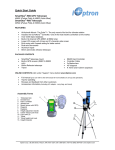
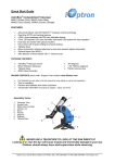
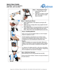
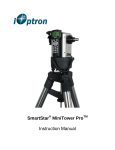
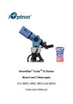
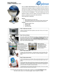
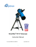
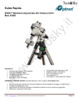
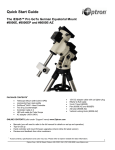
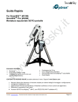
Quick Start Guide
SmartStar®-N114 GPS Telescope
#9803 (Astro Blue)
SmartStar®-N114 Telescope
#9503 (Astro Blue)
FEATURES
•
•
•
•
•
•
•
•
•
Alt-Azimuth Mount– The Cube™-- The only mount of its kind for ultimate rotation
Includes the GoToNovaTM Controller. The most intuitive controller on the market.
Over 5,000 object database.
Built-in 32-channel GPS (#9803 only)
Large LCD screen with 4 lines and 21-character wide screen
Drive motor with 5-speed setting for precise tracking.
Dual-axis Servomotor
Aluminum tripod
114mm Newtonian reflector telescope
PACKAGE CONTENTS
•
•
•
•
®
•
•
•
•
SmartStar telescope mount
Built-in GPS receiver (#9803only)
114mm Newtonian reflector telescope
Tripod
#8405 Hand Controller
Controller Cable
Red dot finder scope
K 9mm and K 25mm eyepieces
ONLINE CONTENTS (click under “Support” menu button) www.iOptron.com
•
•
•
•
Full manual (you can refer to the full manual for more details on set-up and operation).
Tips for operating
Reviews and feedback from other customers
Accessories information (including AC adapter, carry bag, and more)
7
2
3
4
Assembly Terms
1.
2.
3.
4.
5.
6.
7.
8.
9.
10.
11.
12.
13.
6
5
Telescope tube
Dovetail lock
Hand controller
Altitude lock
Mount
Red dot finder scope
Eyepiece
Height adjustment handle
Center Tripod Lock Knob
Leg Locks (3)
Tripod
Tripod height lock knob
Height Extender
1
12
8
13
9
10
11
iOptron Corp. | 6F Gill Street | Woburn, MA 01801 USA | (781) 569-0200 | Toll Free (866) 399-4587 | www.iOptron.com
Quick Start Guide for SmartStar®-N114 Telescopes (with and without GPS)
Step 1.
Unlock the leg locks #10 (shown by arrows at left).
Extend tripod legs.
Lock the leg locks afterwards.
Step 2.
Turn the center tripod lock knob (#9) to secure and stabilize the tripod.
Tighten to a firm feel.
Caution: Make sure you loosen the tripod lock knob before
collapsing the tripod to store away.
Step 3.
Attach mount to tripod by placing the mount onto the threaded bolt on
tripod. Then turn the mount until it is securely fastened to the tripod.
Threaded bolt Use height adjustment handle (#8) to adjust the height of the mount.
(Caution: Do not extend beyond 6 inches from top of tripod.)
#12 knob Make sure to tighten the tripod height lock knob (#12).
#8 Step 4.
Lift the battery cover. Carefully pull out the battery holder from the
compartment. Be sure not to accidentally disconnect the wires.
Step 4a.
Insert 8 AA batteries (not included) in the holder. Refer to the diagram
on the holder to orient the batteries properly. Replace the holder back
into the battery compartment and replace the lid.
For reference: the battery pack fits in with wires on the bottom right.
(See arrow in photo). Use only fresh batteries. Using old or low batteries
may cause error messages.
An optional AC adapter and 12V car plug cable are also available
for purchase at www.iOptron.com.
#2 knob Step 5.
Attach telescope to mount using dovetail lock knob (#2).
iOptron Corp. | 6F Gill Street | Woburn, MA 01801 USA | (781) 569-0200 | Toll Free (866) 399-4587 | www.iOptron.com
Step 6.
Attaching the red dot finder scope (#6) to the telescope tube (#1):
Point toward open end of telescope Bolts First remove the two washers on the tube. Then place the finder scope
onto the two bolts and re-attach the washers securely. The finder scope
should face towards the open end of the tube (see arrow in diagram).
Turn on the beam using the switch on the side. (note: you may need to
remove the plastic insulation placed next to the battery underneath)
Not pictured here: Insert one eyepiece into the receptor and secure with
side screws. Use the large knob on side to adjust the focus.
Step 7.
Plug hand controller into any one of HBX port on the mount.
Switch Turn on power. Now you are ready to observe. Use the 4 Arrow keys
(▲▼◄►) to rotate the scope Up, Down, Left, and Right. Use the
SPEED key to change the slew rate from the slowest (2X) to the fastest
(MAX).
(2) Up (1) South #4 Alt lock Step 8.
Set telescope to PARK POSITION.
(1) Position the mount so that the “SOUTH” mark is facing south
(a compass may be helpful).
(2) The telescope tube should be pointed directly up at the zenith. If it is
not perfectly straight then loosen the altitude lock (#4) to adjust
telescope.
Step 9.
Level the mount using the bubble on side of mount by adjusting tripod
legs. The bubble should be in the middle of the circle. It is also
suggested to use additional levels (such as torpedo levels) to assure
precise leveling.
Step 10.
Press the I/O power switch ON (controller will light up).
For models with GPS: Wait for controller to say “G-OK” or “Stop” in top
right corner —not “G-ON”. GPS provides Latitude, Longitude, and
current time only.
For models without GPS you will be able to manually enter latitude,
longitude, and time in the next steps.
Step 11.
Press the MENU key once.
Scroll (with the ▲/▼ keys) to “Set Up Controller”
Press ENTER.
Scroll to “Set Up Time and Site” in the next screen.
Press ENTER.
iOptron Corp. | 6F Gill Street | Woburn, MA 01801 USA | (781) 569-0200 | Toll Free (866) 399-4587 | www.iOptron.com
Step 12.
Now “Set Local Time:” is displayed at the top. A blinking cursor is at the
second line.
GPS will provide current date and time. If GPS is not available, current
date and time can be manually entered at this screen.
Use ▲/▼ keys to change the numbers. Use ◄/► keys to scroll through
the fields.
The last field of this screen is for setting “DaylightTime saving”.
Use ▲/▼ keys to switch between “Y” (yes) and “N” (no).
Press ENTER when finished.
Step 13.
Now “Setup Site Info:” is displayed at the top. A blinking cursor is at the
second line. (“Longi” means longitude; “Lat” means latitude.)
GPS will provide the longitude and latitude information. If GPS is not
available, these values can be manually entered here.
Use ▲/▼ keys to change the numbers and letters. Use ◄/► keys to
scroll through the fields.
The last line of this screen is for setting time zone information (add or
subtract 60 minutes (Mins.) per time zone).
Examples: minutes “behind” UT or “ahead” of UT
New York: 300 Mins. “behind” UT
Los Angeles: 480 Mins. “behind” UT
Rome: 60 Mins. “ahead” of UT
Sydney: 600 Mins. “ahead” of UT
Press ENTER when finished.
The mount is now ready to find (GOTO) and track objects.
Step 14. Select and Slew to an object
Press Menu button.
Scroll to “Select and Slew”
Press ENTER.
Step 15.
Select a category (ex. “Planets, Sun, Moon”) by scrolling with the arrow
keys.
Press ENTER.
Then select an object (ex. “Moon”) by scrolling with the arrow keys.
Press ENTER.
The telescope will automatically slew to the object and lock on. It will
automatically begin to track once it locks on to the object.
Step 16. Sync to Target (Use this to center and synchronize the object
selected in Step 15).
Press MENU. Scroll to “Sync. To Target”. Press ENTER. Next use the
arrow keys (▲▼◄►) to center the object in the eyepiece. Then press
ENTER again to synchronize the object with the memory.
To slew to other objects simply repeat steps 14 and 15. You do not need
to repeat step 16 except for adjustments as needed.
(Refer to the full online manual for 1-star and 2-star alignments. Sync to
Target is the same as 1-star Alignment except that you choose the
object to align to.)
iOptron Corp. | 6F Gill Street | Woburn, MA 01801 USA | (781) 569-0200 | Toll Free (866) 399-4587 | www.iOptron.com