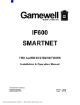
1
Installation Guide
Wireless Audio / Video Kit
1
GUWAVKIT
2
Table of Contents
System Requirements
4
Video Mode Configuration
45
Important Information
5
Screen Resolution Configuration
48
Package Contents
6
Wireless USB Transmitter Settings
51
Device Overview
8
Wireless USB Transmitter Selection
53
Wireless USB Transmitter
8
Wireless USB Transmitter Reset
54
Wireless VGA Receiver
9
Wireless VGA Receiver in Wired Mode
55
Wireless Audio Receiver
11
Trouble Shooting Guide
56
Preparing for Setup
12
Technical Specifications
70
Software Installation
17
Appendix
72
Install Wireless USB Transmitter
25
Limited Warranty
76
Install Wireless VGA Receiver
27
77
Install Wireless Audio Receiver
35
Federal Communications Commission
(FCC) Statement
Advanced Settings
43
Contact
78
Wireless USB Manager
43
3
System Requirements
• Microsoft Windows® XP (SP2) or Vista (32- / 64-bit) with available USB 2.0 port
• 1.6 GHz processor (CPU) with 1GB of system memory (RAM)
• Flat-panel (LCD / Plasma / DLP) TV display or Projector with VGA (RGB / D-sub 15-pin / PC)
or DVI port (Does NOT work with CRT tube TV)
• TV or audio system with 3.5mm audio jack or RCA connectors
Suggested system requirement to play online video clips in a “window” – 1.6 Ghz Atom™ with
1GB RAM, 480p video in a “window” – 1.8 Ghz Pentium™ M with 1GB RAM, 720p video in a
“window” – 2.8 GHz Pentium™ M with 1 GB RAM, 720p video in “full screen” – 2.8 GHz Core™
2 Duo with 1GB RAM.
4
Important Information
Before you get started, please NOTE:
Do not place Wireless USB devices under direct sunlight or near high heat emitting devices;
Do not place Wireless USB devices near water or wet surfaces to avoid electric hazards;
Do not place Wireless USB devices on any moving or unstable surfaces.
5
Package Contents
• 1 x Wireless VGA
receiver (for display)
• 1 x USB 2.0 A to mini-B cable (3 ft.)
• 1 x USB 2.0 extension cable (4 ft.)
• 1 x Wireless Audio
receiver (for stereo)
LI
NK
PW
R
• 1 x Gold Plated VGA cable (6 ft.)
• 1 x Wireless USB
Transmitter (for
computer)
• 1 x 3.5mm to 3.5mm cable
• 1 x VGA (F) to
DVI-A adapter
6
• 1 x 3.5mm to RCA cable
• 1 x Hook-and-loop
fastener
• 1 x Quick Start Guide /
User manual
• 1 x Power adapter for Audio Receiver
• 1 x Installation CD
• 1 x Power adapter for Video Receiver
• 1 x Warranty /
Registration Card
7
Device Overview
Wireless USB Transmitter
1. LINK: Data Transfer Activity Indicator
-- LED blinks when data is being transferred
2. PWR: Power
-- LED is solid when powered by the PC
3. USB Connector
-- Connect to any available USB 2.0 port on your
computer
L
IN
K
P
W
R
1 2
3
8
Wireless VGA Receiver
1
4
2
5
6 7 8
9
3
9
1. VGA : VGA Activity Indicator
-- LED is solid when display cable is connected
-- LED is blinking when data is being transferred
2. PWR: Power Indicator
-- LED is solid when power is applied
3. Status Indicator
-- Single* solid light: device is wirelessly connected to
the selected Wireless USB Transmitter
-- Single* slowly blinking light: device is searching for a
Wireless USB Transmitter
-- Single* quickly blinking light: device is trying to
connect to a Wireless USB Transmitter
-- Rapidly scrolling lights: device is used in wired mode.
-- Three Simultaneous Blinking Lights: Cable
Association Mode
5. Power Plug
-- Power adapter socket
*Only one light at a time. The position of the light indicates
which Wireless USB Transmitter the device is trying to
communicate with.
9. WIRELESS/WIRED switch
-- Choose from wired or wireless mode by using this
switch - P.55
6. RESET Button
-- Association history can be erased by pressing and
holding this button for 10 seconds. (Please visit P.54
for details)
7. HOST Button
-- This button is used to select a different Wireless USB
Transmitter. (Please visit P.53 for details)
8. Mini-B USB port
-- In wireless mode, this port is used for cable
association. (Please visit Appendix for details)
-- In wired mode, connect the VGA adapter with the
USB cable via this port for wired operation. (Please
visit P.55 for details)
4. VGA Connector
-- Connects to one end of the included VGA cable, and
the other end to the VGA or DVI port on your display
10
Wireless Audio Receiver
1. Power/Activity LED
-- LED is solid when connection is established
-- LED is blinking when power is on and connection is
not established
2. 3.5mm Audio Socket
-- Connects to the 3.5mm audio connector of the
included 3.5mm or RCA audio cable, and the other
end to the available 3.5mm audio socket or RCA
audio socket on your display or stereo system
3. Mini-B USB Port
-- Connects to the mini-B end of the included USB
cable, and the Type-A end to an available USB port
on your computer to create association between your
computer and the audio receiver
4. Power plug
-- Power adapter socket
1
2
3
4
11
Preparing for Setup
Before you begin, please make sure to properly remove all previously installed Wireless
USB Manager and DisplayLink drivers from your system to avoid driver conflict. To
properly remove previously installed drivers, please follow below instructions.
For Windows XP users
1. Go to Start -> Control Panel -> Add or Remove Programs
2. Select any previously installed DisplayLink software and click on Remove button to properly uninstall
the program.
3. After all DisplayLink software are uninstalled, please restart your system.
12
4. .Repeat steps 1 and select any previously installed Wireless USB drivers and click on Remove button to
properly uninstall the program.
13
For Windows Vista users
1. Click on the Vista logo. Click on Control Panel then double click on Programs and Features.
2. Select any previously installed Displaylink software and click on Uninstall button to properly uninstall
the program.
14
3. After successfully remove the DisplayLink software, please restart your system.
4. Repeat Step 1 and select IOGEAR Wireless USB to VGA Kit and click on Uninstall.
15
After all previously installed DisplayLink and Wireless USB to VGA Kit software are properly
removed, please make sure to install the software on the CD following the procedures on
the next page before plugging in the Wireless USB Transmitter to your computer.
Important Note:
If installing on Windows XP, Service Pack 2 (SP2)
is required. Please verify that this has been
installed before installing the Wireless Audio/Video
Kit software. Before installing the software, please
make sure the Wireless USB Transmitter and
Wireless VGA and Audio Receivers are not
connected to the computer and not powered.
16
Software Installation – Windows XP
Important Note:
For Windows XP users
For Windows XP users, if you do not have Microsoft .NET Framework 2.0 installed, you will be
prompted to have it installed. Please follow below
instructions for installation.
1. Insert the installation CD into the CD-ROM on
your computer and the InstallShield Wizard will
load automatically.
1. Click “Yes” to install .NET 2.0 Framework
2. Check “License Agreement” and click “Install”
3. Click “Finish” to complete the installation
4. Restart your computer when prompted
5. Eject your CD and follow instructions below to
begin the installation
17
3. Click on “Yes” to accept the software License
Agreement and continue the installation.
2. Click on “Next” to continue.
Note – If you previously installed IOGEAR Wireless
USB Hub and Adapter Kit (GUWH104KIT)
software, please follow detail instructions on P.72
Appendix.
18
4. The InstallShield Wizard will continue loading
the drivers. Do not click on any button, otherwise, it will interrupt the installation process and
cause malfunction of the product.
5. The installation wizard will continue to install the
video driver provided by DisplayLink. Click on
“I Accept” to continue the installation.
19
Note – If this screen does not appear, please make
sure you correctly remove all DispalyLink software
from your system. After un-installation, please
repeat the new software installation procedures
from P.17.
7. Click on “Finish” to complete the software
installation.
6. The DisplayLink driver starts to load. Do not
click on any button, otherwise, it will interrupt
the installation process and cause malfunction
of the product.
It is highly recommended to restart your
system after the software installation to
ensure all drivers are loaded correctly.
20
Software Installation – Windows Vista
For Windows Vista users
3. The InstallShield Wizard will start loading.
1. Insert the installation CD into the CD-ROM on
your computer and click on Run setup.exe to
begin the installation.
2. Click on Allow when prompted User Account
Control window to continue.
21
4. Click on “Next” to continue.
5. Click on “Yes” to accept the software License
Agreement and continue the installation.
22
6. The InstallShield Wizard will continue loading the
drivers. Do not click on any button, otherwise,
it will interrupt the installation process and cause
malfunction of the product.
7. The installation wizard will continue to install the
video driver provided by DisplayLink. Click on
“I Accept” to continue the installation.
23
Note – If this screen does not appear, please make
sure you correctly remove all DispalyLink software
from your system. After un-installation, please
repeat the new software installation procedures
from P.21.
8. The DisplayLink driver starts to load. Do not
click on any button, otherwise, it will interrupt
the installation process and cause malfunction
of the product.
9. Click “Yes” to restart your system.
24
Install Wireless USB Transmitter
1. Make sure the antenna is securely connected to the Wireless USB Transmitter.
2. Plug the Wireless USB Transmitter to your computer via option 1 or 2. Windows will detect the device
and complete the driver installation process automatically.
Option 1:
Plug the Wireless USB Transmitter into any available USB 2.0 port on your computer.
25
Option 2:
To properly connect the Wireless USB Transmitter and avoid interfering with
other USB devices connected to your computer, you can use the included
USB extension cable to connect the Wireless USB Transmitter with your
computer.
Place the USB extension cable on a flat surface, preferably the top of the desk
or work area to ensure a good line-of-sight signal with the Wireless Video and
Audio Receivers.
WR
KP
LIN
26
TV
TV
Install Wireless VGA Receiver
1. Make sure the antenna is connected to the
Wireless Video Receiver
2. Connect one end of the included VGA cable to
the Wireless Video Receiver, and the other end
to your display’s VGA port.
PC Port
Input 1
Input 2
Input 3
Input 4
Audio
PC Port
Input 1
Input 2
Input 3
Input 4
Audio
TV
vGA
PWR 1 2 3
PC Port
vGA
Input 1
Input 2
Input 3
Input 4
PWR 1 2 3
Audio
PC Port
vGA
PWR 1 2 3
27
T
vGA
PWR 1 2 3
Input 1
Input 2
Input 3
Input 4
Audio
Input 1
Input 2
Input 3
Input 4
Audio
Example 1:
For LCD monitor / Flat-Panel TV
Input 1
Input 2
Input 3
Input 4
Audio
PC Port
Input 1
Input 2
Input 3
Input 4
Audio
vGA
PC Port
vGA
PWR 1 2 3
PWR 1 2 3
28
T
PWR 1 2 3
TV
vGA
TV
Input 1
Input 2
Input 3
Input 4
Audio
Example 2:
For Projector
29
TV
Install Wireless Video Receiver – With DVI Connector
For monitor or TV that comes with DVI connector,
you may use the included VGA to DVI-A adapter
to connect the Wireless Video Receiver to your
display. Connect one end of the VGA cable to the
VGA connector of the VGA to DVI-A adapter, then
connect the DVI end of the adapter to the DVI
port on your display.
DVI Port
Important Note: The included DVI-A adapter
only works with displays with DVI-A or DVI-I
connector built-in, it does not work with DVI-D
connector on the display. Please consult the
user manual of your display for further support
information on using DVI port.
Input 1
Input 2
Input 3
Input 4
Audio
TV
DVI Port
Input 1
Input 2
Input 3
Input 4
Audio
vGA
PWR 1 2 3
DVI-I
vGA
PWR 1 2 3
30
3. Plug the power cable into Wireless VGA Receiver and make sure the Power Indicator LED is solid.
Windows will automatically install the drivers for the Wireless VGA Receiver.
Note: Please use the
included power adpater as
shown. This power adapter
is slightly different from the
one for Audio Receiver
on P.35
31
4. Upon successful installation of your Wireless
Video Receiver, double click on the Wireless
USB Manager software icon located in your
system tray.
5. You should see the active Wireless VGA icon
showing up in the software interface.
If you do not see the Wireless USB Manager icon
appears in your system tray, please click on Start,
then select All Programs, then click on Wireless
USB Manager and click again on Wireless USB
Manager to launch the application.
32
6. Please change your display’s source setting
to select VGA / RGB / PC as your video input
source. Refer to the operating instructions
supplied with your display.
PC Port
Input 1
Input 2
Input 3
Input 4
TV
PWR 1 2 3
TV
vGA
Note: You may use the included fabric hook-andloop fastener to attach the Wireless VGA Receiver
to your projector or LCD display / TV in order to
ensure a good line-of-sight signal with the
Wireless USB Transmitter.
Audio
PC Port
vGA
PWR 1 2 3
33
Input 1
Input 2
Input 3
Input 4
Audio
7. Upon successful connection, the installation will
set the best resolution supported by your
display and extend your desktop to the right.
This is called the Extended Mode. You will see
the wallpaper displaying on the monitor/display
that is connected to the Wireless VGA Receiver.
You can click on the Restore Down button on
the top right corner of the application window,
then drag the window to the right side of your
screen. You will then see the window showing
up on the monitor/display that is connected to
the Wireless VGA Receiver.
Note: For advanced display setting, please visit
Video Mode Configuration section on page 45.
34
Installing Wireless Audio Receiver
1.Plug the power cable into the Wireless Audio
Receiver. Make sure the Link Activity LED
turns on and starts blinking. The next step is
to create the association of the Wireless Audio
Receiver and the Wireless USB Transmitter.
Note: The Wireless Audio Receiver will NOT
function until the following association
process is completed.
Note: Please use the
included power adpater as
shown. This power adapter
is slightly different from
the one for Video Receiver
on P.31
35
2. Connect the mini-B end of the USB cable to the mini-B port on the Wireless Audio Receiver, and
connect the other end of the USB cable to your computer.
36
4. Click on OK to complete the association
process.
3. Once connected, the Wireless USB Cable Association window will prompt and please click
on “Accept Association” to continue.
37
5. Disconnect the USB cable from the Wireless
Audio Receiver and your computer.
The Wireless USB Manager will display the
Wireless Audio icon and show the signal strength
when connected. If the Wireless Audio Receiver is
not connected then the Wireless Audio icon will be
grayed out. If you do not see the Wireless Audio
icon displayed after following above steps, please
refer to Trouble Shooting Guide on P.57.
Double click on the Wireless USB manager icon
located in the Windows system tray to verify the
connection has been established successfully.
38
Connecting the Audio Receiver to Speakers
There are 3 options to connect the Wireless Audio Receiver to your TV, home stereo system, or power
speakers.
Option 1:
Connect one end of the 3.5mm audio cable to the Wireless Audio Receiver, and the other 3.5mm end to
the 3.5mm port on your display or stereo system.
39
TV
When connecting the 3.5mm audio cable to the 3.5mm port on your TV or display, make sure you
connect to the 3.5mm port next to the VGA port used to connect your Wireless Video Receiver. Please
refer to the original user manual that came with your TV or display for further instructions.
PC Port
Input 1
Input 2
Input 3
Input 4
Audio
TV
PC Port
Input 1
Input 2
Input 3
Input 4
Audio
40
Option 2:
Connect the 3.5mm end of the 3.5mm to RCA cable to the Wireless Audio Receiver, and the RCA (Red &
White) end to your stereo system or TV’s RCA input sockets.
41
Option 3:
Connect your powered speakers’ 3.5mm audio cable directly to the Wireless Audio Receiver.
Congratulations, your Wireless Audio / Video Kit is ready for use.
Note:
For quick trouble-shooting guide, please go to P.56.
For more information on using your Wireless Audio / Video Kit for different applications, please visit
IOGEAR’s website for detail instructions.
42
Advanced Settings – Wireless USB Manager
The Wireless USB Manager is a simple and easyto-use interface that allows you to manage your
Wireless USB devices and control your Wireless
USB Transmitter settings. The Wireless USB
Manager can be accessed via the Wireless USB
Manager icon located in the Windows system tray.
To Launch the Wireless USB Manager, double click
on the Wireless USB Manager icon in your system
tray. On the main pane, you will find an icon
representing your Wireless VGA and Wireless
Audio Receivers. If your Wireless VGA or Audio
Receiver is not connected, the icon will be grayed
out.
43
If your Wireless VGA Receiver is connected and
working, then the icon will change and show the
current signal strength.
The View menu will give the option of what type
of devices you wish to display (All Devices, Connected Devices and Disconnected Devices).
The Options menu will give the option to launch
Host Settings window and turn the Wireless USB
Transmitter radio on or off.
The Help menu offers quick help on how to connect devices to your Wireless USB Transmitter.
44
Advanced Settings – Video Mode Configuration
Note: If no output is seen on the monitor connected
to the Wireless VGA Receiver, it may be in a mode
which cannot be displayed by the monitor. This
can happen if the monitor is not adjusted to the
mode supported by the Wireless VGA Receiver.
Please refer to the operating instructions supplied
with your display and try adjusting the resolution of
the primary display until an image is shown.
There are two options to adjust the resolution,
color quality, screen rotation, and between extended or mirror mode.
1. On the Monitor icon in the system tray to access
the menu.
2. Go through Control Panel, double click on “Display”, then choose “Settings” tab.
By default, the installation will set the best resolution supported for your computer and extend your
screen to the right.
In this user manual, we will show you how to
access the advanced setting feature by double
clicking on the Monitor icon in the system tray.
45
Extended Mode
Extended mode enables the extension of the
desktop across multiple monitors.
You can choose to extend your desktop to 4
different orientations: right, left, above, and
below, of your desktop.
To set up extended mode, click on the monitor
icon located in your system tray to access the
DisplayLink menu.
46
Mirror Mode
Mirror mode duplicates the primary display (your
desktop) to the monitor connected to the Wireless
VGA Receiver.
You can choose Mirror from the menu to enable
the mirror mode. You should see duplicated
desktop showing up on the monitor that is
connected to the Wireless VGA Receiver.
After setting up the display settings, you may now
click on the monitor icon located in your system
tray to access the DisplayLink menu.
47
Advanced Settings - Screen Resolution Configuration
You may change the video resolution under
extended or mirror mode.
Extended Mode
To change the screen resolution when in Extended
Mode, please follow below instructions.
Click on the monitor icon located in your system
tray to access the DisplayLink menu.
Choose the available resolution setting from the
list.
In the extended mode, the available resolution depends on the resolution supported by the display
that is connected to the Wireless VGA Receiver.
48
Mirror Mode
When using in the Mirror Mode, click on
“Advanced” from the menu to bring up the
Display Settings window.
Windows XP
For Windows XP users, you can then click and
drag the arrow bar to switch between different
resolutions and click on Apply then OK to confirm.
49
Windows Vista
For Windows Vista users, you can click and
drag the arrow bar to switch between different
resolutions, and click on Apply then OK to
confirm.
50
Advanced Settings - Wireless USB Transmitter Settings
To manage the Wireless USB Transmitter settings, double click on the Wireless USB Manager icon in the
system tray to bring up the Wireless USB Manager window. Click on Options and select Host Settings.
• General Settings
1.Enable this Wireless USB radio: to turn on or off the
Wireless USB radio.
2.Host Name: you can change the name of your
Wireless USB Transmitter.
3.Connection Rules: this is connection rule when
creating cable association with the Wireless USB
Transmitter and any Wireless Receiver. It is set to
Ask me each time to ensure connection security.
You can change to other setting that is suitable to
you.
4.Host Information: this shows the firmware version of
your Wireless USB Transmitter.
51
• Advanced Settings
Channel selection: this function allows
you to manually set a radio channel
(not recommended) for the wireless
communication (combination of Band
Group and Channel).
For optimal performance, the automatic
setting is recommended.
52
Advanced Settings - Wireless USB Transmitter Selection
If you purchase more than one Wireless USB
Transmitter (GUWA200), then you can use the
HOST button on the Wireless Video Receiver
to select and connect to different Wireless USB
Transmitter. However, before you pressing this
button to select another Wireless USB
Transmitter, please make sure to go through the
cable association process to associate the
Wireless USB Transmitter and Wireless Video
Receiver. For more information on the cable
association process, please refer to the Appendix
on P.73.
If multiple Wireless USB Transmitters have been
associated with the Wireless Video Receiver, you
may have to press the HOST button multiple times
before a connection is made with the desired
Wireless USB Transmitter. There are up to 16
Wireless USB Transmitters can be associated with
your Wireless Video Receiver.
53
Advanced Settings - Wireless USB Transmitter Reset
To erase all Wireless USB Transmitters (except the
Wireless USB Transmitter included in this kit)
associated* to your Wireless VGA Receiver, hold
down the “RESET” button on the Wireless VGA
Receiver for 10 seconds. This will cause the
Wireless VGA Receiver to erase all Wireless USB
Transmitters that have been associated from its list.
Each Wireless USB Transmitter will then have to be
re-associated with the Wireless VGA Receiver using
the cable association process in order to connect
to the Wireless VGA Receiver again.
*For more information about the association, please
refer to P.73 Appendix - Cable association with
other devices.
54
Advanced Settings - Wireless VGA Receiver in Wired Mode
Your Wireless VGA Receiver can also be used in
wired mode. Make sure the position of the
WIRED / WIRELESS switch is in the WIRED
position. Plug the USB cable between your
computer and the Wireless VGA Receiver. The
function is the same as the wireless mode but
data will be transferred through the cable and
does not require the use of the Wireless USB
Transmitter.
55
Trouble Shooting Guide
Installation and setup related Q&A …………………………………. P.57
Connection and signal quality related Q&A ………………………... P.64
Video and Audio Receivers configuration related Q&A …………… P.68
56
Trouble Shooting Guide
For the latest FAQs, please go to IOGEAR website (www.iogear.com).
1.Why can’t I install .NET?
You may have an older version of .NET, preventing the newer one from being installed. Using Add/
Remove Programs (For Windows XP users) or Programs and Features (For Windows Vista users) in
the Control Panel, uninstall any version of Microsoft .NET Framework older than version 2.0. Then
install Microsoft .NET Framework from the Wireless Audio / Video Kit CD.
2.My Wireless USB Transmitter is plugged into my computer and my Wireless Video is powered on but I
do not see anything on my display. What’s wrong?
Check the Wireless USB Manager to see if there is an icon for your Wireless Video Receiver. If there
is no icon, try unplugging and plugging in your Wireless USB Transmitter back to your computer to
reload the driver.
57
If you see an icon that is grayed out in the Wireless
USB Manager, try resetting the Wireless VGA
Receiver by unplugging its power cord and
plugging it back in. You should see the icon in the
Wireless USB Manager appearing in color when it
is connected.
Still not connected?
Double check that the radio for your Wireless USB
Transmitter is on in the Wireless USB Manager.
58
3. My Wireless USB Transmitter is plugged into my
computer and my Wireless Audio Receiver is
powered on but I do not hear anything. What’s
wrong?
Check the Wireless USB Manager to see if there
is an icon for your Wireless Audio Receiver. If
there is no icon, try unplugging and plugging
your Wireless USB Transmitter to your
computer, then unplugging and plugging your
power adapter to your Wireless Audio Receiver
to reset the connection.
59
4. My Wireless USB Transmitter is plugged into
one of the USB ports on my computer and my
Wireless Audio and Video Receivers are powered on, but I get this window and I do not hear
or see anything. What do I do?
Please try to unplug and re-plug the Wireless
USB Transmitter into the USB port, and you
should see the USB logo becomes colored.
Once the USB logo becomes colored, then you
should see the Wireless Audio and Wireless
VGA icons shows in color and your Wireless Audio & Video Kit should become functional again.
Besides unplugging and re-plugging in the Wireless USB Transmitter, you can also try to power
cycle the Audio and VGA Receivers as this will
help to reset the wireless connection.
60
5. I already reset my Wireless USB Host
Transmitter and Audio Receiver, and the icon
does show up in the Wireless USB Manager.
But there is still no sound, what’s wrong?
Windows XP
For XP users, please go to Start -> Control
Panel -> Sounds and Audio Devices, then
select Audio tab and make sure the USB
Multimedia Audio Device is selected then
click OK.
61
Windows Vista
For Vista users, right click on the Speaker
icon at the bottom right corner of your system
tray, then make sure the “2- USB Multimedia
Audio Device” is checked then click Set
Default and OK.
62
6. Why do I get this window during the association
process?
If you idle for more than 45 seconds during
the cable association process, you will see this
window prompt. Just click OK to close the
window, and repeat the association process
again and you should not see this window
again.
Please note, DO NOT idle more than 45 seconds during the cable association process.
63
7. I successfully installed everything and I can see video and hear audio from my TV, but the signal is bad
and I can not get smooth video and audio quality. What can I do to get a better signal?
First of all, please make sure the distance between the Wireless USB Transmitter and Wireless Video
and Audio Receivers is within 30 feet. Wireless USB technology is a in-room solution and it does not
work beyond 30 feet of range.
Second, please make sure the antenna of your Wireless USB Transmitter keeps a clearance of
minimum 3” off the desktop surface and have a good line-of-sight with the Wireless Video and Audio
Receivers. Due to different home and office setup and unknown interference, we recommend using the
included USB extension cable to connect with the Wireless USB Transmitter and find a suitable position
for good signal.
You can also try to unplug and plug the Wireless USB Transmitter back into your computer to reset the
connection. You should see the icon in the Wireless USB Manager becomes grayed out then color
again. Now try to restart the application that you were using and check if the signal quality improves.
64
8. The video and audio signals seem to drop out when I walk in front of the Wireless USB Transmitter or
put my hands around the antenna. What should I do to get a better signal?
It is the most important thing to ensure a good line-of-sight between the Wireless USB Transmitter and
the Wireless Receivers. Therefore, we recommend not putting your hands or any obstacles between
the Wireless USB Transmitter and the Wireless Receivers to ensure good signal.
65
9. If you are experiencing video or audio quality
problems, please try following procedures for
solutions.
• Adjust the screen resolution to the appropriate
setting supported by your monitor/display,
please refer to P.48 for detail instructions.
• The Wireless Audio / Video Kit requires certain
level of system resource for smooth operation.
Try to close other applications on your computer to free up the system resource.
• Does your computer meet the minimum
system requirements? Please refer to P.4 for
more information.
• The Wireless Audio / Video Kit requires radio
signals to be in the line of sight. Please
ensure to eliminate as much interferences as
possible between the Wireless Transmitter
and the Wireless Video and Audio Receivers.
• Change the channel as shown on the right or
move in your computer closer to the display.
66
11. I accidentally unplug the power from my
Wireless Audio Receiver, and the sound is
gone. How do I make it work again?
10. I accidentally unplug the power from my
Wireless Video Receiver, and the movie
becomes playing on my main display of my
computer. How do I bring it back to the other
(extended) monitor?
Please stop the movie or music that is currently playing and close the player on the computer. Plug in the power adapter back to the
Wireless Audio Receiver. Restart your movie
or music and you should be able to hear the
sound again. If this is not working, please refer
to page 61 and make sure the correct audio
device is selected on your computer.
Please stop the movie that is currently playing
and close the player on the computer. Plug in
the power adapter back to the Wireless Video
Receiver. Restart your movie and you should
be able to drag the movie to the extended
monitor.
67
12. I already setup my Wireless USB Transmitter
and Audio Receiver, and the icon does show
up in the Wireless USB Manager. However,
I would like the sound to be streaming from
the built-in speakers of my computer, how do
I do that?
First of all, close the multimedia application you
are currently running, and you have to change
the playback device settings to activate the
built-in speakers on your computer.
For Windows XP users, please go to Start
-> Control Panel -> Sounds and Audio
Devices, then select Audio tab and make sure
to select your default audio device and click
Apply then OK.
Do not select USB Multimedia Audio Device
as this is the driver for Wireless Audio Receiver.
68
For Vista users, right click on the Speaker icon
at the bottom right corner of your system tray,
then right click on your default speaker device
and select Set as default device on the
device and click OK.
DO NOT select 2- USB Multimedia Audio
Device as this is the driver for the Wireless
Audio Receiver.
Now you may restart the multimedia application
you were using for your music, and the music
should be coming off from the built-in speakers
on your computer.
69
Technical Specifications
Function
GUWAVKIT
Audio
Audio Output
2 CH DAC output
Dynamic Range
95db, THD+N -85db ~ -91db
Sample Rate
8KHz, 16KHz, 44.1KHz, to 48KHz with 16-bit resolution
Antenna Type
Omni directional
Video Resolution
Up to UXGA 1600x1200 or WSXGA+ 1680x1050
Video Streaming
Up to 720p
Color Depth
32-bit true color
Interface
Audio: 3.5mm TRS audio connector ; Video: VGA female
connector
Frequency Band
3.1GHz ~ 4.8GHz (WiMedia Band Group 1)
Number of Channel
7 Channels (3 FFI + 4 TFI)
70
Function
GUWAVKIT
Operating Range
Up to 30 feet (10 meters)
Operating System Support
Microsoft XP 32-bit; Vista 32/64-bit
PHY Data Rate
53.3Mbps, 80Mbps, 106.6Mbps, 160Mbps, 200Mbps,
320Mbps, 400Mbps, 480Mbps
RF Modulation Type
QPSK/DCM
Security
Highly secured wireless connection (AES 128-bit)
USB Specification
Certified Wireless USB 1.0; Certified USB 2.0
Power Supply
Audio Adapter: 5V, 1Ah, 100-240VAC; Video Adapter: 5V,
2Ah; 100-240VAC
Environment
Humidity
10-95% RH, Non-condensing
Operation Temperature
0°C to 50°C
Storage Temperature
0°C to 75°C
71
Appendix
I. Compatibility with IOGEAR Wireless USB Hub and Adapter Kit (GUWH104KIT)
Important: To retain the functionality of both the Wireless Audio / Video Kit and the GUWH104KIT, you
MUST follow these steps:
1. Uninstall the GUWH104KIT software by using Add/Remove Programs or Programs and Features on
the Control Panel. Please select and remove “Ultrasuite with WiCenter Basic”. The Wireless Audio /
Video Kit installer will not allow you to proceed until this software is removed.
2. Complete the installation of the Wireless Audio / Video Kit as shown in the Wireless VGA Software
Installation section.
3. Install the GUWH104 software “Driver Hub Only” for your Wireless USB Hub from IOGEAR
website. Please make sure that you are in the correct product page.
http://www.iogear.com/support/dm/driver/GUWH104#display
4. Use the Wireless USB Host Adapter (GUWA200) that comes with this kit to communicate with your
Wireless USB Hub.
Note: After this upgrade, the Wireless USB Host Adapter (GUWA100U) will not function with the
Wireless VGA Receiver (GUW2015V) or the Wireless USB Hub (GUWH104) on the PC system
where the GUW2015VKIT software has been installed. However you may use this Wireless USB
Host Adapter (GUWA100U) on a different PC.
For more support information, please contact IOGEAR.
72
II. Cable association with other devices
Association Concept:
In order to establish a secure wireless connection between both the Wireless USB Transmitter and the
Wireless USB devices, you will need to go through the cable association process. The association process
will allow the Wireless USB Transmitter and the Wireless USB device to exchange security information
about each other necessary to operate in a secured wireless mode.
Association Process:
If you purchase additional Wireless USB devices, you will have to associate them with your Wireless USB
Transmitter. Refer to your Wireless USB device documentation for more information on its settings for
cable association.
73
Cable association steps:
1. Make sure that the Wireless USB Manager is running. Check your Windows tray for the Wireless
USB Manager icon.
2. Power on your Wireless USB device.
3. Connect the USB cable between an available
USB port on your computer and your
Wireless USB device.
4. Complete cable association by pressing the
“Accept Association” button when prompted.
5. Remove the USB cable from your Wireless
USB device and computer then follow
instructions specific to your Wireless USB
device for wireless operation.
74
Associated Wireless USB devices will appear as icons in the Wireless USB Manager. When the Wireless
USB device is connected to your computer, the icon will appear in color.
75
Limited Warranty
IN NO EVENT SHALL THE DIRECT VENDOR’S LIABILITY FOR DIRECT, INDIRECT, SPECIAL,
INCIDENTAL OR CONSEQUENTIAL DAMAGES RESULTING FROM THE USE OF THE PRODUCT,
DISK, OR ITS DOCUMENTATION EXCEED THE PRICE PAID FOR THE PRODUCT.
The direct vendor makes no warranty or representation, expressed, implied, or statutory with respect to
the contents or use of this documentation, and especially disclaims its quality, performance,
merchantability, or fitness for any particular purpose.
The direct vendor also reserves the right to revise or update the device or documentation without
obligation to notify any individual or entity of such revisions, or updates. For further inquiries please
contact IOGEAR.
76
Federal Communications Commission (FCC) Statement
This device complies with part 15 of the FCC Rules. Operation is subject to the following two conditions:
(1) this device may not cause harmful interference, and (2) this device must accept any interference
received, including interference that may cause undesired operation. This device is authorized under 47
CFR 15.519 (the FCC Rules and Regulations). The operation of this device is subject to the following
restriction: This UWB device shall transmit only when it is sending information to an associated receiver.
This UWB device shall cease transmission within 10 seconds unless it receives an acknowledgement from
the associated receiver that its transmission is being received. An acknowledgement of reception must
continue to be received by the transmitting device at least every 10 seconds of operation or the UWB
device must cease transmitting.
77
Contact
IOGEAR
23 Hubble
Irvine, CA 92618
P 949.453.8782
F 949.453.8785
Visit us at: www.iogear.com
© 2009 IOGEAR® Part No. M1094
IOGEAR, the IOGEAR logo, are trademarks or registered trademarks of IOGEAR, Inc. Microsoft and Windows are registered trademarks of
Microsoft Corporation. All other brand and product names are trademarks or registered trademarks of their respective holders. IOGEAR makes
no warranty of any kind with regards to the information presented in this document. All information furnished here is for informational purposes
only and is subject to change without notice. IOGEAR, Inc. assumes no responsibility for any inaccuracies or errors that may appear in this
document.
78
Customer’s Record
The model number and serial number of this product can be found on the product package. You should
note this serial number in the space provided below and retain this book, plus your purchase receipt, as a
permanent record of your purchase to aid in identification for Warranty Service purposes.
Model Number
Serial Number
Note
79
About Us
FUN
IOGEAR offers connectivity solutions that are innovative, fun, and stylish,
helping people enjoy daily life using our high technology products.
GREEN
IOGEAR is an environmentally conscious company that emphasizes the
importance of conserving natural resources. The use of our technology solutions
helps reduce electronic waste.
HEALTH
IOGEAR supports healthy and fit lifestyles. By integrating products with
the latest scientific developments, IOGEAR’s solutions enhance the life of
end-users.
PART NO. M1094
© 2009IOGEAR®