1
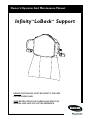
Owner's Operator And Maintenance Manual
Infinity LoBack Support
TM
TM
DEALER: THIS MANUAL MUST BE GIVEN TO THE USER
OF THE WHEELCHAIR.
USER: BEFORE USING THIS WHEELCHAIR, READ THIS
MANUAL AND SAVE FOR FUTURE REFERENCE.
SPECIAL NOTES/TABLE OF CONTENTS
S
P
E
C
I
A
L
N
O
T
E
S
WARNING
THE PROCEDURES IN THIS MANUAL MUST BE PERFORMED BY A
QUALIFIED TECHNICIAN.
DO NOT INSTALL OR USE THIS EQUIPMENT WITHOUT FIRST
READING AND UNDERSTANDING THIS MANUAL. IF YOU ARE
UNABLE TO UNDERSTAND THE WARNINGS, CAUTIONS, AND
INSTRUCTIONS, CONTACT A HEALTHCARE PROFESSIONAL,
DEALER OR TECHNICAL PERSONNEL IF APPLICABLE BEFORE
ATTEMPTING TO INSTALL OR USE THIS EQUIPMENT - OTHERWISE
INJURY OR DAMAGE MAY RESULT.
SPECIAL NOTES
NOTICE
THE INFORMATION CONTAINED IN THIS DOCUMENT IS SUBJECT TO CHANGE WITHOUT NOTICE.
WARNING/CAUTION notices as used in this manual apply to hazards or unsafe practices which
could result in personal injury or property damage.
T
A
B
L
E
SAVE THESE INSTRUCTIONS
TABLE OF CONTENTS
O
F
SPECIAL NOTES ................................................ 2
C
O
N
T
E
N
T
S
IMPORTANT INFORMATION ............................... 5
PROCEDURE 3 - INSTALLING/REMOVING THE
INFINITY LOBACK ......................................... 10
INSTALLING/REMOVING THE INFINITY
LOBACK ..................................................... 10
SAFETY SUMMARY ........................................... 3
PROCEDURE 4 - ADJUSTING THE
INFINITY LOBACK ......................................... 11
ADJUSTING THE MOUNTING
HARDWARE/HEIGHT ................................. 11
ADJUSTING THE DEPTH HARDWARE .......... 11
ADJUSTING THE ANGLE ............................... 12
ADJUSTING THE LATERAL SUPPORTS ........ 13
INSTALLATION/ADJUSTMENT OVERVIEW ........ 5
PROCEDURE 1 - PREPARING WHEELCHAIR .... 6
INSTALLING/REMOVING CANE CLAMPS ........ 6
PROCEDURE 2 - PREPARING THE
INFINITY LOBACK FOR INSTALLATION .......... 7
INSTALLING/REMOVING THE
LATERAL SUPPORTS ................................... 7
INSTALLING/REMOVING THE BACK
CUSHION ..................................................... 8
INSTALLING/REMOVING THE MODESTY
FLAP ............................................................ 9
PROCEDURE 5 - MAINTENANCE ..................... 15
INSTALLING/REMOVING CUSHION FOAM .... 15
INSPECTION ................................................. 15
CLEANING .................................................... 15
LIMITED WARRANTY .................... BACK COVER
2
SAFETY SUMMARY
SAFETY SUMMARY
NOTE: Check all parts for shipping damage. In case of damage, DO NOT use. Contact your Dealer for further instruction.
INSTALLATION WARNINGS
Stabilize from the ground up. A stable base, pelvis and footrests are requirements for any torso
positioning system.
For proper installation of the Infinity LoBack and to reduce the risk of pressure sores, the adjustment procedures in this manual MUST be performed in the following order:
1.
2.
3.
4.
Adjusting the Mounting Hardware/Height
Adjusting the Depth Hardware
Adjusting the Angle
Adjusting the Lateral Supports
Ensure the cane clamps that secure the Infinity LoBack to the wheelchair are properly secured to
the wheelchair BEFORE using. Otherwise, changes in seat depth will occur, making the wheelchair less stable.
After ANY adjustments, repair or service and BEFORE use, make sure all attaching hardware is tightened securely - otherwise injury or damage may occur.
STABILITY WARNINGS
Rear Wheel Position
✓
●
✓
✓
✓
✓
✓
●
✓
✓
✓
✓
✓
✓
✓
●
✓
✓
✓
✓
●
✓
✓
✓
✓
●
✓
✓
✓
✓
✓
✓
✓
✓
✓
✓
✓
✓
✓
✓
✓
✓
✓
✓
✓
✓
✓
✓
✓
✓
✓
✓
✓
✓
✓
✓
✓
✓
✓
✓
✓
✓
●
✓
✓
✓
✓
✓
✓
●
✓
✓
✓
✓
✓
✓
✓
✓
✓
●
✓
✓
✓
✓
✓
✓
✓
✓
✓
✓
✓
●
✓
✓
✓
✓
✓
✓
✓
✓
✓
✓
✓
✓
✓
✓
✓
✓
✓
✓
✓
✓
✓
Seat Dump
Rear Wheel Size
✓
Locking Collar
Caster Position
✓
Anti-Tippers
Seat Frame Pivot Point
✓
●
Wheel Locks
Tilt Angle
✓
✓
●
User Condition
Seating System
✓
✓
Seat Depth
Back Angle
Seat Height
Back Height
Seat Depth
Back Angle
Seating System
Tilt Angle
Seat Frame Pivot Point
Caster Position
Rear Wheel Size
Rear Wheel Position
User Condition
Seat Dump
Locking Collar
Back Height
Seat Height
The seat height, seat depth, back height, tilt angle, back angle, pivot point of seat frame, seating
system, caster position, size and position of the rear wheels, wheel locks, anti-tippers, locking collar as well as the user condition directly relate to the stability of the wheelchair. Any change to
one (1) or any combination of the fourteen (14) may cause the wheelchair to decrease in stability. Use EXTREME caution when using a new seating position.
✓
✓
✓
✓
✓
✓
●
●
NOTE: When changes to the left hand column occur, follow across the chart and refer to the ✓ procedure to
maintain the proper stability, safety and handling of the wheelchair.
NOTE: Additional adjustments may be needed according to the wheelchair type. Refer to the wheelchair
owner's manual for these procedures.
3
S
A
F
E
T
Y
S
U
M
M
A
R
Y
SAFETY SUMMARY
S
A
F
E
T
Y
S
U
M
M
A
R
Y
SAFETY SUMMARY
STABILITY WARNINGS (CONTINUED)
ALWAYS make sure wheelchair is stable BEFORE reclining the back system. Rear wheels may have
to be repositioned rearward depending on the degree of recline. ALWAYS ensure stability BEFORE
using maximum amount of recline. TEST wheelchair BEFORE it is occupied by end user to ensure
stability.
To maintain the stability of the wheelchair when moving the rear wheels to ANY forward position,
the amount of recline MUST be limited to prevent the wheelchair from tipping onto the antitippers.
The necessary back angle MUST be selected BEFORE repositioning rear wheels forward.
AS REGARDS RESTRAINTS - SEAT POSITIONING STRAPS - IT IS THE OBLIGATION OF THE DME DEALER,
THERAPISTS AND OTHER HEALTH CARE PROFESSIONALS TO DETERMINE IF A SEAT POSITIONING STRAP
IS REQUIRED TO ENSURE THE SAFE OPERATION OF THIS EQUIPMENT BY THE USER. SERIOUS INJURY
CAN OCCUR IN THE EVENT OF A FALL FROM A WHEELCHAIR.
SEATING PRESSURE WARNING
Skin condition should be checked very frequently after the installation and use of any new seating system.
GENERAL WARNINGS
Care should be taken to prevent the hook and loop fasteners from becoming wet. Prolonged
contact with moisture may reduce the hold of the hook and loop fastners.
4
IMPORTANT INFORMATION/INSTALLATION/ADJUSTMENT OVERVIEW
IMPORTANT INFORMATION
The best way to avoid problems related to pressure sores
is to understand their causes and your role in a skin management program.
All cushions should be selected carefully. Working with
your therapist, physician and equipment supplier is the
best way to assure that a cushion choice matches your
individual needs.
Your therapist and physician should be consulted if you
have any questions regarding weight relief, self-examination of skin, or individual limitations and needs.
As the needs of the client become more complex, the
cushion evaluation becomes more important.
INSTALLATION/ADJUSTMENT OVERVIEW
INSTALLATION/ADJUSTMENT OVERVIEW (FIGURE 1)
I
N
F
O
R
M
A
T
I
O
N
WARNING
For proper installation of the Infinity LoBack and to reduce the risk of pressure sores, the adjustment
procedures in this manual MUST be performed in the following order:
3. Adjusting the Angle
1. Adjusting the Mounting Hardware/Height
4. Adjusting the Lateral Supports
2. Adjusting the Depth Hardware
Follow the steps below in order. Refer to the procedure below each step.
STEP 2
Install/remove the lateral
supports. Refer to INSTALLING/
REMOVING THE
LATERAL SUPPORTS in
PROCEDURE 2 of this manual.
STEP 8
Adjust the lateral supports.
Refer to ADJUSTING THE
LATERAL SUPPORTS in
PROCEDURE 4 of this
manual.
STEP 3
Install the back cushion. Refer
to INSTALLING/REMOVING
THE BACK CUSHION in
PROCEDURE 2
of this manual.
STEP 4
Install the Infinity LoBack.
Refer to INSTALLING/
REMOVING THE INFINITY LOBACK in PROCEDURE 3 of this manual.
STEP 7
Adjust the angle.
Refer to ADJUSTING ANGLE in
PROCEDURE 4 of
this manual.
STEP 1
Install the cane
clamps onto the
wheelchair. Refer to
INSTALLING/
REMOVING CANE
CLAMPS in PROCEDURE 1 of this
manual.
STEP 6
Adjust the depth of the Infinity
LoBack. Refer to ADJUSTING
THE DEPTH HARDWARE in
PROCEDURE 4 of this manual.
STEP 5
Adjust the height of the Infinity
LoBack. Refer to ADJUSTING
THE MOUNTING HARDWARE/
HEIGHT in PROCEDURE 4 of
this manual.
FIGURE 1 - INSTALLATION/ADJUSTMENT OVERVIEW
5
O
V
E
R
V
I
E
W
PROCEDURE 1
P
R
E
P
A
R
I
N
G
W
H
E
E
L
C
H
A
I
R
PREPARING WHEELCHAIR
Removing Cane Clamps
This Procedure includes the following:
Installing/Removing Cane Clamps
1. Remove the Infinity LoBack from the wheelchair.
Refer to REMOVING THE INFINITY LOBACK in
PROCEDURE 3 of this manual.
INSTALLING/REMOVING CANE
CLAMPS (FIGURE 1)
2. Loosen, but do not remove the two (2) mounting
screws on the two (2) cane clamps.
3. Remove the two (2) cane clamps from the two (2)
back canes of the wheelchair.
WARNING
After ANY adjustments, repair or service and
BEFORE use, make sure that all attaching hardware is tightened securely - otherwise injury or
damage may result.
Cane Clamp
NOTE: Refer to the INSTALLATION AND STABILITY
WARNINGS in the SAFETY SUMMARY of this manual.
Installing Cane Clamps
Mounting Screw
(Faces TOWARD
the REAR of the
Wheelchair)
NOTE: The final mounting positions of the cane clamps
will be determined by the adjustments made to the Infinity LoBack to fit the wheelchair and user.
1. Remove the existing back upholstery. Refer to the
wheelchair Owner's Manual.
2. Hold the Infinity LoBack up to the back canes at the
desired mounting height.
3. Visually inspect the location of the clamps on the Infinity LoBack to determine the proper positions for
each cane clamp.
4. Loosen, but do not remove the mounting screw on
one (1) of the cane clamps.
5. Position the cane clamp on one (1) back cane, making sure that the HEAD of the mounting screw faces
TOWARD the REAR of the wheelchair . Hand tighten
ONLY.
Back Cane
NOTE: It is NOT necessary to tighten the two (2) mounting screws on the two (2) cane clamps at this time. The
two (2) cane clamps will be adjusted AFTER the Infinity
LoBack has been installed on the wheelchair and the
user has been evaluated.
6. Repeat STEPS 5-6 to install the other cane clamp on
the opposite back cane.
FIGURE 1 - INSTALLING/REMOVING CANE
CLAMPS
NOTE: Make sure that the two (2) cane clamps are in the
position determined in STEP 3 AND that the two (2) cane
clamps are in the same position on each back cane by
measuring the distance from the bottom of each back cane
to the bottom of each cane clamp.
6
PREPARING THE INFINITY LOBACK FOR INSTALLATION
PROCEDURE 2
Removing
This Procedure includes the following:
Installing/Removing the Lateral Supports
Installing/Removing the Back Cushion
Installing/Removing the Lower Flap
1. Remove the back cushion from the back panel. Refer
to INSTALLING/REMOVING CUSHIONS in this procedure of the manual.
2. Remove the (2) mounting screws and washers securing the lateral support to the back panel.
INSTALLING/REMOVING THE
LATERAL SUPPORTS (FIGURE 1)
3. Remove the lateral support.
WARNING
After ANY adjustments, repair or service and
BEFORE use, make sure that all attaching hardware is tightened securely - otherwise injury or
damage may result.
4. Repeat STEPS 2-3 for the remaining lateral supports,
if necessary.
T
H
E
DETAIL “A”
L
O
B
A
C
K
Lateral
Support
Upper
Mounting
Holes
NOTE: Refer to the INSTALLATION AND STABILITY
WARNINGS in the SAFETY SUMMARY of this manual.
P
R
E
P
A
R
I
N
G
Installing
Middle
Mounting
Holes
NOTE: The final mounting positions of the lateral supports will be determined by the adjustments made to the
Infinity LoBack to fit the wheelchair and user.
Lower
Mounting
Holes
1. Remove the back cushion from the back panel. Refer to INSTALLING/REMOVING THE BACK CUSHION in this procedure of the manual.
F
O
R
NOTE: The lateral supports can be adjusted to three (3)
different height positions (DETAIL “A”).
2. Align the upper, middle or lower mounting holes in
the lateral support with the toothed adjustment slots
in the back panel (DETAIL “A”).
Lateral
Support
NOTE: The grooves next to the mounting holes in the
lateral supports are provided to ensure that opposite lateral supports are installed using the SAME mounting holes
(FIGURE 1). To ensure that this occurs, install one (1)
lateral support at the desired height and look through the
toothed adjustment slot to see which mounting holes have
been used. Then, install the opposite lateral support using the SAME mounting holes.
Toothed
Adjustment
Slot
Grooves
3. Install the two (2) mounting screws and washers that
secure the lateral support to the back panel. Hand
tighten ONLY.
Mounting
Screws
NOTE: It is NOT necessary to tighten the mounting screws
on the lateral support at this time. The lateral supports will
be adjusted AFTER the Infinity LoBack has been installed
on the wheelchair and the user has been evaluated.
Back Panel
FIGURE 1 - INSTALLING/REMOVING THE
LATERAL SUPPORTS
4. Repeat STEPS 2-3 to install the OPPOSITE lateral
support.
5. Reinstall the back cushion onto the back panel. Refer to INSTALLING/REMOVING THE BACK CUSHION in this procedure of the manual.
7
I
N
S
T
A
L
L
A
T
I
O
N
PROCEDURE 2
P
R
E
P
A
R
I
N
G
T
H
E
L
O
B
A
C
K
PREPARING THE INFINITY LOBACK FOR INSTALLATION
INSTALLING/REMOVING THE BACK
CUSHION (FIGURE 2)
2. Align the hook and loop fasteners on the BACK of the
cushion with the hook and loop fasteners on the
FRONT of the back panel (DETAIL “A”).
NOTE: Refer to the INSTALLATION AND STABILITY
WARNINGS in the SAFETY SUMMARY of this manual.
NOTE: Make sure the cushion is centered on the back panel.
The cushion covers are designed to protect the
foam against moisture and to provide fire
retardency. DO NOT use the back without the
covers. If the covers are torn, they MUST be replaced immediately.
3. Make sure the hook and loop fasteners meet by firmly
pushing the cushion and back panel together. (DETAIL “A”).
4. Grasp the folding hook and loop fastener on the cushion and fold them over the TOP of the back panel,
making sure they meet the hook and loop fastener
on the BACK of the back panel (DETAIL “A”).
NOTE: Invacare recommends the use of a fire retardent
cushion with the Infinity LoBack.
5. Grasp the fixed flap AND the modesty flap and fold
them so they cover the BACK of the back panel.
CAUTION
6. Align the two (2) hook and loop fasteners at the TOP
of the modesty flap with the two (2) hook and loop
fasteners at the BOTTOM of the cushion (DETAIL “B”).
Installing
1. Lift up on the modesty flap AND the fixed flap that
covers the BACK of the cushion, and fold them so
they hang over the FRONT of the cushion.
NOTE: Modesty flap and fixed flap not shown in DETAIL “A” and DETAIL “B” for clarity.
DETAIL “A”
DETAIL “B”
NOTE: Front of back panel/ hook and loop fastener (STEP
2-3) not shown for clarity.
F
O
R
I
N
S
T
A
L
L
A
T
I
O
N
Hook and
Loop
Fastener
Folding Hook
and Loop
Fasteners
of
Bottom n
o
Cushi
Top of
Back
Panel
NOTE: Modesty flap
and fixed flap should
hang on front side of
the cushion during
installation/removal.
Hook and
Loop
Fasteners
Hook and
Loop
Fastener
Top of p
ty Fla
Modes
TOP VIEW
of
ck n
a
B hio
s
Cu
Hook and
Loop
Fastener
Bottom of Cushion
Top of
Back Panel
Hook and
Loop
Fasteners
Top of
Modesty
Flap
Back of
Back Panel
Hook and
Loop
Fasteners
FIGURE 2 - INSTALLING/REMOVING THE BACK CUSHIONS
8
PREPARING THE INFINITY LOBACK FOR INSTALLATION
PROCEDURE 2
2. Grasp the modesty flap and pull DOWN to release
the hook and loop fasteners at the TOP of the REAR
side of the modesty flap from the hook and loop fasteners at the BOTTOM of the FRONT side of the
fixed flap (DETAIL “A”).
7. Make sure the hook and loop fasteners meet by firmly
pushing the TOP of the modesty flap and the BOTTOM of the cushion together.
Removing
3. Remove the modesty flap.
1. Grasp the modesty flap AND the fixed flap.
2. Pull UP to release the two (2) hook and loop fasteners on the TOP of the modesty flap from the two (2)
hook and loop fasteners on the BOTTOM of the cushion (DETAIL “B”).
DETAIL “A”
NOTE: The hook and loop fasteners on the front side of
the fixed flap are not shown for clarity.
2. Fold the modesty flap AND the fixed flap over the
FRONT of the cushion.
T
H
E
L
O
B
A
C
K
Hook and Loop
Fasteners
3. Grasp the two (2) folding hook and loop fasteners on
the cushion and pull UP to release them from the two
(2) hook and loop fasteners on the BACK of the back
panel (DETAIL “A”).
P
R
E
P
A
R
I
N
G
Bottom of
Fixed Flap
4. Grasp the cushion and pull it away from the back
panel to release the remaining hook and loop fasteners on the cushion and back panel (DETAIL “A”).
5. Remove the cushion.
Top of Modesty Flap
INSTALLING/REMOVING THE
MODESTY FLAP (FIGURE 3)
Rear Side
F
O
R
NOTE: Refer to the INSTALLATION AND STABILITY
WARNINGS in the SAFETY SUMMARY of this manual.
Installing
DETAIL “B”
1. Align the hook and loop fasteners at the TOP of the
REAR side of modesty flap with the hook and loop
fasteners at the BOTTOM of the FRONT side of the
fixed flap (DETAIL ”A”).
2. Make sure the hook and loop fasteners meet by firmly
pushing the TOP of the modesty flap and the BOTTOM of the fixed flap together (DETAIL “A”).
Folding Hook and
Loop Fasteners
3. Align the two (2) hook and loop fasteners at the TOP
of the FRONT side of the modesty flap with the two
(2) folding hook and loop fasteners at the BOTTOM
of the REAR side of the cushion (DETAIL “B”).
Bottom Of
Cushion
4. Make sure the hook and loop fasteners meet by firmly
pushing the TOP of the modesty flap and the BOTTOM of the cushion together, making sure the hook
and loop fasteners meet (DETAIL ”B”).
Top of
Modesty
Flap
Removing
1. Grasp the two (2) hook and loop fasteners at the
TOP of the FRONT side of the modesty flap and pull
UP to release them from the two (2) hook and loop
fastener at the BOTTOM of the REAR side of the
cushion (DETAIL “B”).
Hook And Loop Fasteners
FIGURE 3 - INSTALLING/REMOVING THE
MODESTY FLAP
9
I
N
S
T
A
L
L
A
T
I
O
N
PROCEDURE 3
I
N
S
T
A
L
L
I
N
G
/
R
E
M
O
V
I
N
G
INSTALLING/REMOVING THE INFINITY LOBACK
A. ADJUSTING THE MOUNTING HARDWARE/
HEIGHT
B. ADJUSTING THE DEPTH HARDWARE
C. ADJUSTING THE ANGLE
D. ADJUSTING THE LATERAL SUPPORTS
This Procedure includes the following:
Installing/Removing the Infinity LoBack
INSTALLING/REMOVING THE
INFINITY LOBACK (FIGURE 1)
WARNING
After ANY adjustments, repair or service and
BEFORE use, make sure that all attaching hardware is tightened securely - otherwise injury or
damage may result.
NOTE: Refer to the INSTALLATION AND STABILITY
WARNINGS in the SAFETY SUMMARY of this manual.
Installing the Infinity LoBack
1. Ensure the two (2) cane clamps are properly installed
onto the wheelchair frame. Refer to INSTALLING/
REMOVING CANE CLAMPS in PROCEDURE 1 of
this manual.
2. If necessary, adjust the Infinity LoBack to fit on the
back canes. Refer to ADJUSTING THE INFINITY
LOBACK in PROCEDURE 4 of this manual.
NOTE: Perform the above procedures in the order listed.
11. Inspect all mounting screws to ensure ALL hardware
has been tightened securely. Torque to 45-50 in./lbs.
13. If necessary, repeat STEPS 8-11 until the user is comfortable.
Removing the Infinity LoBack
1. Grasp the handle of one (1) of the locking pins and
push it BACK to release the lock, and then pull it UPWARD until the handle is parallel with the rest of the
locking pin.
2. Repeat STEP 5 for the opposite locking pin.
3. Grasp the Infinity Loback from the bottom and pull
upward to release it from the mounting pins on the
two (2) cane clamps.
4. Remove the Infinity LoBack.
DETAIL “A”
3. Align the mounting holes in the two (2) Infinity LoBack
mounting clamps with the locking pins on the two (2)
cane clamps (FIGURE 1).
T
H
E
4. Lower the Infinity LoBack onto the wheelchair back
canes, making sure the locking pins on the two (2)
cane clamps pass through the mounting holes in the
two (2) mounting clamps of the Infinity LoBack.
L
O
B
A
C
K
5. Firmly grasp the handle of the locking pin and bend it
o
DOWN until it forms a 90 angle with the rest of the
locking pin, then push it FORWARD to fully engage
the lock. (DETAIL “A”).
Handle
Pull Handle
Forward to
Engage Lock
Locks to
Form A
90o Angle
Locking
Pin
Infinity LoBack
NOTE: The locking pin is fully engaged when the handle
of the locking pin bends down to form a 90° angle with the
rest of the of the locking pin.
Mounting
Clamp
6. Repeat STEP 5 for the opposite locking pin.
7. Ensure all cushions and lateral supports have been installed. Refer to PREPARING THE INFINITY BACK
FOR INSTALLATION in PROCEDURE 2 of this
manual.
8. Position the user into the wheelchair to determine
which adjustments need to be made to properly fit
the Infinity LoBack. Refer to the wheelchair owner’s
manual.
Mounting Hole
Locking Pin
9. Remove the user from the wheelchair. Refer to the
wheelchair owner’s manual.
10. Perform the following procedures to adjust the Infinity LoBack to fit the user if necessary. Refer to ADJUSTING THE INFINITY LOBACK in PROCEDURE
4 of this manual.
Cane Clamp
Back Cane
FIGURE 1 - INSTALLING/REMOVING THE INFINITY
LOBACK
10
ADJUSTING THE INFINITY LOBACK
PROCEDURE 4
6. Torque the mounting screw to 45-50 in./lbs.
This Procedure includes the following:
Adjusting the Height
Adjusting the Depth Hardware
Adjusting the Angle
Adjusting the Lateral Supports
7. Repeat STEPS 2-6 for the opposite cane clamp.
NOTE: Make sure that the two (2) cane clamps are in the
same position on each back cane by measuring the distance from the bottom of each back cane to the bottom of
each cane clamp.
9. Reinstall the Infinity LoBack onto the wheelchair. Refer
to INSTALLING/REMOVING THE INFINITY
LOBACK in PROCEDURE 3 of this manual,
WARNING
For proper installation of the Infinity LoBack and
to reduce the risk of pressure sores, the adjustment procedures below MUST be performed in
the following order:
1.
2.
3.
4.
Adjusting the Mounting Hardware/Height
Adjusting the Depth Hardware
Adjusting the Angle
Adjusting the Lateral Supports
Cane
Clamp
NOTE: After performing each procedure, place the user
in the wheelchair and inspect to ensure the correct adjustments have been made for user comfort. If necessary, repeat the procedure until the user is comfortable.
Move Up
Or Down
ADJUSTING THE MOUNTING
HARDWARE/HEIGHT (FIGURE 1)
NOTE: Refer to the INSTALLATION AND STABILITY
WARNINGS in the SAFETY SUMMARY of this manual.
Mounting
Screw
1. Remove the Infinity LoBack from the wheelchair. Refer
to INSTALLING/REMOVING THE INFINITY
LOBACK in PROCEDURE 3 of this manual,
2. Loosen the mounting screw on the cane clamp.
FIGURE 1 - ADJUSTING THE MOUNTING
HARDWARE/HEIGHT
3. Move the cane clamp up or down until the desired
position is acheived.
4. Loosen the two (2) mounting screws on the two (2)
cane clamps.
ADJUSTING THE DEPTH
HARDWARE
5. Perform one (1) of the following to achieve the desired depth:
NOTE: Refer to the INSTALLATION AND STABILITY
WARNINGS in the SAFETY SUMMARY of this manual.
NOTE: The depth of the Infinity LoBack can be adjusted by
maneuvering the cane clamps AND/OR by pivoting the adjustment brackets.
Adjusting the Cane Clamps (Figure 2)
A. To INCREASE depth, rotate the two (2) cane
clamps so that the locking pins are facing the
REAR of the wheelchair.
B. To DECREASE depth, rotate the two (2) cane
clamps so that the locking pins are facing the
FRONT of the wheelchair.
1. Remove the Infinity LoBack from the wheelchair. Refer
to INSTALLING/REMOVING THE INFINITY
LOBACK in PROCEDURE 3 of this manual,
NOTE: By rotating the locking pins on the cane clamps
toward the front or rear of the wheelchair, numerous depth
positions can be achieved.
2. Hold the Infinity LoBack up to the wheelchair.
6. Torque the two (2) mounting screws on the two (2)
cane clamps to 45-50 in./lbs.
3. Visually inspect the Infinity LoBack and the wheelchair to determine the desired depth.
11
A
D
J
U
S
T
I
N
G
T
H
E
L
O
B
A
C
K
PROCEDURE 4
A
D
J
U
S
T
I
N
G
ADJUSTING THE INFINITY LOBACK
7. Reinstall the Infinity LoBack onto the wheelchair. Refer
to INSTALLING/REMOVING THE INFINITY
LOBACK in PROCEDURE 3 of this manual.
NOTE: When loosening the mounting screws/nuts, it is
necessary to firmly hold the nuts in place while turning
the mounting screws.
5. Perform one (1) of the following to achieve the desired depth:
Locking Pin
A. To INCREASE depth, pivot the two (2) adjustment brackets so that the mounting screws and
nuts are facing the REAR of the chair.
Mounting
Screws
Cane Clamps
T
H
E
L
O
B
A
C
K
B. To DECREASE depth, pivot the two (2) adjustment brackets so that the mounting screws and
nuts are facing the FRONT of the chair.
FRONT
Rotate
Cane
Clamps
Toward
Rear to
INCREASE
Depth
Rotate
Cane
Clamps
Toward
Front to
DECREASE
Depth
6. Torque the two (2) mounting screws and nuts to 4550 in./lbs (DETAIL “B”).
7. Reinstall the Infinity LoBack onto the wheelchair. Refer
to INSTALLING/REMOVING THE INFINITY
LOBACK in PROCEDURE 3 of this manual.
REAR
TOP VIEW
REAR
To
INCREASE
Depth
Cane Clamp
Mounting
Screw
FRONT
Adjustment
Bracket
Should be
Angled
Toward
Front to
DECREASE
Depth
REAR
Adjustment
Bracket
Locking
Pin
Adjustment Bracket
Should be
Angled Toward
Rear to INCREASE
Depth
Nut
TOP VIEW
To
DECREASE
Depth
To
INCREASE
Depth
FRONT
REAR
Adjustment
Bracket
FIGURE 2 - ADJUSTING THE CANE CLAMPS
Pivoting The Adjustment Brackets (Figure 3)
1. Remove the Infinity LoBack from the wheelchair. Refer
to INSTALLING/REMOVING THE INFINITY
LOBACK in PROCEDURE 3 of this manual,
Mounting Screw
2. Hold the Infinity LoBack up to the wheelchair.
3. Visually inspect the Infinity LoBack and the wheelchair to determine the desired depth.
To
DECREASE
Depth
4. Loosen the two (2) mounting screws and nuts on the
two (2) adjustment brackets.
FRONT
FIGURE 3 - PIVOTING THE ADJUSTMENT
BRACKETS
12
ADJUSTING THE INFINITY LOBACK
PROCEDURE 4
B. To DECREASE the angle of the Infinity LoBack,
grasp the TOP of the Infinity Loback and push
FORWARD.
ADJUSTING THE ANGLE (FIGURE 4)
NOTE: Refer to the INSTALLATION AND STABILITY
WARNINGS in the SAFETY SUMMARY of this manual.
1. Remove the back cushion from the back panel. Refer to INSTALLING/REMOVING THE BACK CUSHION in PROCEDURE 2 of the manual.
2. Loosen the two (2) mounting screws on the two (2)
angle brackets.
3. While standing behind the wheelchair, perform one
(1) of the following:
A. To INCREASE the angle of the Infinity LoBack, grasp
the TOP of the Infinity LoBack and pull BACK.
NOTE: Modesty flap and fixed flap not shown for clarity.
TO INCREASE
ANGLE:
Grasp Here
and Pull
BACK
TO DECREASE
ANGLE:
Grasp Here
and Push
FORWARD
4. Torque the two (2) nuts on the two (2) angle brackets
to 45-50 in./lbs.
5. Reinstall the back cushion onto the back panel. Refer to INSTALLING/REMOVING THE BACK CUSHION in PROCEDURE 2 of the manual.
ADJUSTING THE LATERAL
SUPPORTS
NOTE: Refer to the INSTALLATION AND STABILITY
WARNINGS in the SAFETY SUMMARY of this manual.
Adjusting the Width (Figure 5)
1. Remove the back cushion from the back panel. Refer to INSTALLING/REMOVING THE BACK CUSHION in PROCEDURE 2 of the manual.
2. Loosen, but DO NOT remove the two (2) mounting
screws that secure the lateral support to the back
panel.
3. Position the user in the wheelchair.
4. Slide one (1) lateral support to the desired location.
5. Torque the two (2) mounting screws that secure the
lateral support to the back panel to 45-50 in./lbs.
6. Repeat STEPS 1-4 for the remaining lateral support.
7. Reinstall the back cushion onto the back panel. Refer to INSTALLING/REMOVING THE BACK CUSHION in PROCEDURE 2 of the manual.
Back Panel
Angle Bracket
Slide Lateral
Support to the
Desired Location
Mounting
Screw
SIDE VIEW
TO DECREASE
ANGLE:
Grasp Here
and Push
FORWARD
Lateral
Support
TO INCREASE
ANGLE:
Grasp Here
and Pull
BACK
Mounting
Screws
NOTE: Modesty flap and fixed flap not shown for clarity.
FIGURE 4 - ADJUSTING THE ANGLE
FIGURE 5 - ADJUSTING THE WIDTH
13
A
D
J
U
S
T
I
N
G
T
H
E
L
O
B
A
C
K
PROCEDURE 4
A
D
J
U
S
T
I
N
G
T
H
E
L
O
B
A
C
K
ADJUSTING THE INFINITY LOBACK
Adjusting the Height (Figure 6)
DETAIL “A”
NOTE: The lateral supports can be adjusted to three (3)
different height positions (DETAIL “A”).
Lateral
Support
Upper
Mounting
Holes
1. Remove the back cushion from the back panel. Refer to INSTALLING/REMOVING THE BACK CUSHION in PROCEDURE 2 of the manual.
Middle
Mounting
Holes
2. Remove the two (2) mounting screws securing the
lateral support to the back panel.
3. Position the lateral support in the upper, middle or
lower position, aligning the mounting holes of the lateral support with the toothed adjustment slot in the
back panel (DETAIL “A”).
Lower
Mounting
Holes
NOTE: The grooves next to the mounting holes in the
lateral supports are provided to ensure that opposite lateral supports are installed using the SAME mounting
holes. To ensure that this occurs, install one (1) lateral
support at the desired height position and look through
the toothed adjustment slot to see which mounting holes
have been used. Then, install the opposite lateral support using the SAME mounting holes.
Lateral
Support
Toothed
Adjustment
Slot
4. Install the two (2) mounting screws to secure the supports to the back panel.
Grooves
5. Repeat STEPS 1-3 for the remaining lateral support.
6. Torque the two (2) mounting screws that secure the
lateral support to the back panel to 45-50 in./lbs.
7. Adjust the width of the lateral supports. Refer to ADJUSTING THE WIDTH in this procedure of the manual.
8. Reinstall the back cushion onto the back panel. Refer to INSTALLING/REMOVING THE BACK CUSHION in PROCEDURE 2 of the manual.
Mounting
Screws
Back Panel
NOTE: Modesty flap and fixed flap not shown for clarity.
FIGURE 6 - ADJUSTING THE HEIGHT
14
MAINTENANCE
PROCEDURE 5
INSPECTION
This Procedure includes the following:
Installing/Remove Back Cushion Foam
Inspection
Cleaning
WARNING
INITIALLY AND ONCE A WEEK, visually inspect
all parts, including hardware, upholstery materials, foams (if accessible), and plastics for
deformation, corrosion, breakage, wear and/
or compression.
REPLACING THE BACK CUSHION
FOAM (FIGURE 1)
Check ALL fasteners weekly to ensure that mechanical connections are secure.
NOTE: Refer to the INSTALLATION AND STABILITY
WARNINGS in the SAFETY SUMMARY of this manual.
DO NOT continue to use this product if any of
the conditions described above are discovered.
1. Remove the back cushion from the back panels. Refer
to INSTALLING/REMOVING THE BACK CUSHIONS in PROCEDURE 2 of this manual.
2. Position the back cushion on a flat surface with the
zipper facing UPWARDS.
NOTE: Corrective maintenance can be performed at or
arranged through your equipment supplier.
WARNING
Skin condition should be checked very frequently
after the installation and use of any new seating system.
3. Unzip the zipper.
4. Grasp the EXISTING cushion foam and remove it
from the back cover.
5. Align the NEW cushion foam with the hole in the back
cover.
CLEANING
NOTE: Make sure the plastic insert on the NEW cushion
foam is facing the REAR of the back cover and that the
fingers on the plastic insert face the TOP of the back
cover.
Cover
6. Position the NEW cushion foam inside the back cover.
7. Position the zipper inside the pouch.
8. Reinstall the back cushion onto the back panels. Refer to INSTALLING/REMOVING THE BACK CUSHIONS in PROCEDURE 2 of this manual.
Back Cover
1. Machine wash the back covers in cold water on gentle
cycle using a mild detergent ONCE A WEEK.
WARNING
When washing the back covers - DO NOT use
fabric softeners or bleach. DO NOT machine
dry. Air dry ONLY. DO NOT dry in sun.
Failure to follow the washing instructions CAN
reduce the flame retardency of the back
cover.
Foam
Care should be taken to prevent the back cushion foam
from getting wet. If the back cushion foam begins to deteriorate from prolonged contact with moisture, it should be
replaced immediately.
Rear of Cushion
Fingers
Zipper
Cushion
Foam
Plastic
Insert
FIGURE 4 - REPLACING THE BACK
CUSHION FOAM
15
M
A
I
N
T
E
N
A
N
C
E
LIMITED WARRANTY
PLEASE NOTE: THE WARRANTY BELOW HAS BEEN DRAFTED TO COMPLY WITH FEDERAL LAW APPLICABLE TO PRODUCTS MANUFACTURED AFTER JULY 4, 1975.
This warranty is extended only to the original purchaser/user of our products.
This warranty gives you specific legal rights and you may also have other legal rights which vary
from state to state.
Invacare warrants its products to be free from defects in materials and workmanship for use by
the original purchaser for a period of two (2) years from the date of purchase on the back and
ninety (90) days from the date of purchase on the cover. If within such warranty period any such
product shall be proven to be defective, such product shall be repaired or replaced, at Invacare's
option. This warranty does not include any labor or shipping charges incurred in replacement
part installation or repair of any such product. Invacare's sole obligation and your exclusive remedy under this warranty shall be limited to such repair and/or replacement.
For warranty service, please contact the dealer from whom you purchased your Invacare product. In the event you do not receive satisfactory warranty service, please write directly to Invacare at the address at the bottom of this page. Provide dealer’s name, address, date of purchase,
indicate nature of the defect and, if the product is serialized, indicate the serial number. Do not
return products to our factory without our prior consent.
LIMITATIONS AND EXCLUSIONS: THE FOREGOING WARRANTY SHALL NOT APPLY TO SERIAL NUMBERED PRODUCTS IF THE SERIAL NUMBER HAS BEEN REMOVED OR DEFACED, PRODUCTS SUBJECTED
TO NEGLIGENCE, ACCIDENT, IMPROPER OPERATION, MAINTENANCE OR STORAGE, COMMERCIAL
OR INSTITUTIONAL USE, PRODUCTS MODIFIED WITHOUT INVACARE'S EXPRESS WRITTEN CONSENT
INCLUDING, BUT NOT LIMITED TO, MODIFICATION THROUGH THE USE OF UNAUTHORIZED PARTS OR
ATTACHMENTS; PRODUCTS DAMAGED BY REASON OF REPAIRS MADE TO ANY COMPONENT WITHOUT THE SPECIFIC CONSENT OF INVACARE, OR TO A PRODUCT DAMAGED BY CIRCUMSTANCES
BEYOND INVACARE'S CONTROL, AND SUCH EVALUATION WILL BE SOLELY DETERMINED BY INVACARE. THE WARRANTY SHALL NOT APPLY TO PROBLEMS ARISING FROM NORMAL WEAR OR FAILURE
TO ADHERE TO THESE INSTRUCTIONS.
THE FOREGOING WARRANTY IS EXCLUSIVE AND IN LIEU OF ALL OTHER EXPRESS WARRANTIES. IMPLIED WARRANTIES, IF ANY, INCLUDING THE IMPLIED WARRANTIES OF MERCHANTABILITY AND FITNESS FOR A PARTICULAR PURPOSE, SHALL NOT EXTEND BEYOND THE DURATION OF THE EXPRESSED
WARRANTY PROVIDED HEREIN AND THE REMEDY FOR VIOLATIONS OF ANY IMPLIED WARRANTY
SHALL BE LIMITED TO REPAIR OR REPLACEMENT OF THE DEFECTIVE PRODUCT PURSUANT TO THE
TERMS CONTAINED HEREIN. INVACARE SHALL NOT BE LIABLE FOR ANY CONSEQUENTIAL OR INCIDENTAL DAMAGES WHATSOEVER.
THIS WARRANTY SHALL BE EXTENDED TO COMPLY WITH STATE/PROVINCIAL LAWS AND REQUIREMENTS.
Invacare Corporation
www.invacare.com
USA
Canada
One Invacare Way
Elyria, Ohio USA
44036-2125
800-333-6900
5970 Chedworth Way
Mississauga, Ontario
L5R 3T9, Canada
905-890-8838
Invacare is a registered trademark of Invacare Corporation.
© 1999 Invacare Corporation
Form No. 99-221
Part No. 1095174
Rev A (1) 02/00