1
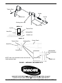
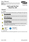
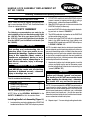
HANDLE LOCK ASSEMBLY REPLACEMENT KIT
KIT NO. 1090768
Assembly, Installation and Operating Instructions
2. If EXISTING handle lock and/or EXISTING roll pin is
present, remove by tapping out the roll pin using a
center punch - otherwise proceed to STEP 3.
SAVE THESE INSTRUCTIONS
NOTE: Check all parts for shipping damage before using. In case of damage, DO NOT use. Contact the Dealer/
Carrier for further instructions.
3. Slide EXISTING spring on to the narrow end of the
EXISTING coil pin (If necessary).
SAFETY SUMMARY
4. Insert the EXISTING coil pin and spring into the bushing arm lock as shown in FIGURE 1.
The following recommendations are made for the
safe installation of the Lock Handle Assembly Kit (Kit
No. 1090768). This kit is used where Roll Pin (Part
No. 1079151) is used with Right Hand Lock Handle
(Part No.1068937) and Left Hand Lock Handle (Part
No. 1068938).
5. The NEW handle lock is placed on to the EXISTING
coil pin and bushing arm lock.
6. Ensure hole in the EXISTING coil pin is aligned with
holes in the NEW handle lock, insert tubular rivet
through NEW handle lock and EXISTING coil pin as
in FIGURE 1 DETAIL "A".
GENERAL WARNING
DO NOT assemble or use this kit without
first reading and understanding this instruction sheet. If you are unable to understand the Warnings, Cautions or Instructions in this Instruction Sheet contact a
healthcare professional, dealer or technical personnel before attempting to install this kit, otherwise, injury or damage
may occur.
NOTE: If unable to insert tubular rivet due to frame interference or otherwise, push the existing coil pin so that the narrow end of the existing coil pin is visible at the other end of
the bushing arm lock and can be rotated to allow the tubular rivet to be inserted through both the new handle lock
and the existing coil pin. (constant pressure will be needed
on the coil pin to insert in this manner).
7. Head end of tubular rivet is butted against a hard flat
surface and lightly tap the end of the center punch
into the hollowed end of the tubular rivet causing it to
"spread" (DETAIL "B").
INSTALLATION WARNINGS
After ANY adjustments, repair or service
and BEFORE use, make sure all attaching
hardware is tightened securely - otherwise
injury or damage may occur.
WARNING
When installing the tubular rivet ensure the
hollow end is evenly "spread" and secures
the handle lock. DO NOT use excessive force
when installing the tubular rivet - otherwise
the handle lock may not function properly.
This kit contains the following:
DESCRIPTION
Handle Lock (Right Hand)
Handle Lock (Left Hand)
Tubular Rivet
*QTY
1
1
2
NOTE: it is recommended that STEP 7 be performed on
a work bench or similar structure. If the head end of the
tubular rivet can not be butted against a hard flat surface
due to frame interference or otherwise, use a solid object
(piece of metal, tool handle, ect...) that fits the space between the head end of tubular rivet and the frame interference or otherwise to hold rivet in place.
*NOTE: These quantities are per kit.
NOTE: Refer to the GENERAL WARNINGS in the
SAFETY SUMMARY of this Instruction Sheet.
Installing Handle Lock Assembly (Figure 1)
8. Repeat steps 1-7 on remaining bushing handle lock.
1. Locate bushing arm lock and determine if EXISTING
handle lock and/or the EXISTING roll pin are present.
1
Tubular Rivet
Spring
Handle Lock
Coil Pin
Bushing Arm Lock
(Narrow End)
DETAIL "A"
Coil Pin
Tubular Rivet
Head End
Hollowed End
Handle Lock
DETAIL "B"
Hollowed End
Tubular Rivet
Center Punch
Head End
Handle Lock
NOTE: After rivet installation ensure that the lock
handle operates freely.
Hollowed End
(After Installation)
Tubular Rivet
Handle Lock
FIGURE 1 - INSTALLING THE HANDLE LOCK
INVACARE CORPORATION ● ONE INVACARE WAY ● ELYRIA, OH 44035
Customer Service (800) 333-6900 ● Technical Support (800) 832-4707
Form No. 99-186
Part No. 1092333
Rev. A (1) - 8/99
Printed in USA