1
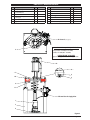
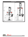
OPERATOR’S MANUAL
NP623XXXXR8-XX
INCLUDING: OPERATION, INSTALLATION AND MAINTENANCE.
INCLUDE MANUALS: 650691-XXX-B Extrusion Pump (97999-832), 66731-X Follower Plate (pn 97999-213),
67342-X Follower Assembly (pn 97999-1099), 67347-X Follower Assembly (pn 97999-1102), RM052S-X Two
Post Lift / Ram (pn 97999-1345), & S-636 General Information (pn 97999-636).
6” AIR MOTOR
23:1 RATIO
6” STROKE
RELEASED:
REVISED:
(REV. 01)
12-10-08
NP623XXXXR8-XX
EXTRUSION SYSTEM
For use with 5 gallon / 20 liter drums (tapered or straight)
READ THIS MANUAL CAREFULLY BEFORE INSTALLING,
OPERATING OR SERVICING THIS EQUIPMENT.
It is the responsibility of the employer to place this information in the hands of the operator. Keep for future reference.
The original language of this manual is English.
SERVICE KITS
y
y
y
y
y
y
NP623EXX3R8-XX EXTRUSION SYSTEM
Use only genuine ARO® replacement parts to assure compatible pressure rating and longest service life.
61355 for repair of 65665-B air motor.
104302 for repair of P39124-100 filter / regulator.
104453 for repair of P39344-100 filter / regulator.
637071-XX3-B for repair of 66243-XX3-B lower pump end.
637466 for repair of lift / ram seals.
MODEL DESCRIPTION CHART
NP 6 23 E XXX R8 - XX
Air Motor Size
6 - 6”
Pump Ratio
23 - 23:1
Check Type / Wetted Materials
E - Chop-Check / Carbon Steel
Lower Pump End Options
Refer to pump model operator’s manual
Ram Style
R8 - Two Post, 5 gallon
Follower Assembly
10 - 67342-1
11 - 67342-2
12 - 67342-3
20 - 66732
21 - 66732-1
Figure 1
22
30
31
40
41
-
66732-2
67347-1
67347-2
67347-11
67347-12
GENERAL DESCRIPTION
By delivering a smooth, continuous bead of the proper size, an
ARO system helps the operator maintain both production rate and
produce high quality standards. Maintained quality standards assures that the material benefits are realized. To further maximize
operator production time, the ARO system has a built-in lift / ram
feature for quick and easy drum changeover and easy lifting of the
pump assembly from the container.
ARO systems are totally enclosed, sealing the material in the system from air and moisture, preventing premature cure-out of the
material. This allows for either continuous or intermittent use of the
system and allows the need for daily system clean-up.
INGERSOLL RAND COMPANY LTD
P.O. BOX 151 y ONE ARO CENTER y BRYAN, OHIO 43506-0151
(800) 276-4658 y FAX (800) 266-7016
fluids.ingersollrand.com
© 2008
CCN 15324080
INSTALLATION
The NP623XXXXR8-XX Extrusion System comes completely assembled. Remove the unit from the crate and place on a level surface.
Install the material hose and dispensing device as required.
When the following instructions are observed, heavy paste materi-
als can be pumped directly from their original drum without air
inclusion or excessive waste. The follower plate creates an air tight
seal as well as clean-wiping action in its progressive downward
movement into the drum.
OPERATING INSTRUCTIONS
OPERATING INSTRUCTIONS / INITIAL SET-UP PROCEDURE
Read the warnings on page 2 of RM052S-X Two Post Lift / Ram
Operator’s Manual.
WARNING Stand clear when raising or lowering the lift.
LIFT / RAM, PUMP AND FOLLOWER PLATE AIR CONTROLS
A
B
C
D
E
F
G
H
-
Air inlet (1/2 - 14 NPT)
Lift / ram pressure gauge
Lift / ram air filter / regulator
Follower plate air supply valve
Lift / ram control lever
Pump air filter / regulator
Pump air supply valve
Pump pressure gauge
Follower plate air supply valve
OFF
Figure 2
ON
97102 Label
TO RAISE THE LIFT, (THE FIRST TIME):
1. Take note of the pump / drum clearance above. Be certain the
lift / ram is clear of any objects above. Also, refer to “Operating
and Safety Precautions” found on page 2 of RM052S-X Two Post
Lift / Ram Operator’s Manual.
2. Connect the air supply (125 p.s.i. / 8.6 bar max.) to the air inlet.
Adjust the air pressure on the lift / ram pressure regulator (turn
the knob clockwise) to 20 p.s.i. (1.4 bar).
3. Shift the control valve lever to the “up” position.
4. Raise the lift / ram high enough to clear the height of the drum.
Stop the lift upward travel by moving the control valve lever to
the “neutral” (center) position.
5. Once the lift / ram assembly and pump are in the “up” position,
place and center an opened drum of material on the lift / ram
base.
6. Lubricate the lower follower wiper plate seal with grease. NOTE:
Make certain the grease is compatible with the material being
dispensed. This ensures a smooth fit into the drum, as well as
prevents curing type compounds from bonding to the seal.
7. Check the vent plug on the follower plate to be sure it easily
threads in and out. It is recommended to lubricate the threads
of the plug to help prevent possible set-up of the compound at
this point (see RM052S-X Operator’s Manual).
TO LOWER LIFT:
WARNING PINCH HAZARD. Follower can descend quickly,
causing injury. Keep hands clear when aligning with container. Read the warnings on page 2 of RM052S-X Two Post Lift
/ Ram Operator’s Manual.
NOTE: Be certain the follower plate vent plug has been removed
so that the air trapped between the follower and the material is al-
E
D
A
B
C
F
H
G
lowed to escape from this vent.
NOTE: The lift / ram may hesitate momentarily before starting
downward. The air pressure inside the post air chamber must decrease before it will begin to descend.
1. Shift the control valve lever to the “down” position and proceed
to lower the pump.
2. Replace the vent plug once the material begins to ooze from
the vent opening.
3. The unit is now ready for operation. Open the pump air supply
valve. Adjust the air pressure on the pump filter / regulator (turn
the pump regulator knob clockwise) until the pump begins to
cycle.
4. Trigger the gun to prime the pump with material.
TO RAISE LIFT, (NORMAL OPERATION):
1. Close the pump air supply valve.
2. Shift the control valve lever to the “up” position.
3. Raise the lift / ram high enough to clear the height of the drum.
Stop the lift upward travel by moving the control valve lever to
the “neutral” (center) position.
TO CHANGE THE DRUM:
NOTE: The control valve lever must be in the “neutral” position and
the pump air supply valve should be closed.
1. To avoid damage, DO NOT OVER PRESSURIZE THE DRUM.
2. Open the follower plate air supply valve to allow air under the
follower plate.
3. Shift the control valve lever to the “up” position.
4. Place and center a new drum into position. Remove the cover.
y ARO® is a registered trademark of Ingersoll-Rand Company y
Page 2 of 4
NP623XXXXR8-XX (en)
PARTS LIST / NP623XXXXR8-XX
Item Description (size)
1 Pump Assembly
2 Male Elbow (1/2 - 14 NPT x 1/2” o.d. tube)
Qty Part No.
(1) 650691-XX3-B
(1) 59756-362
(included with item 3)
3 Two Post Lift / Ram
4 Follower Assembly (see "Model Description
(1) RM052S-C
(1)
Chart", page 1)
5 Lock Washer (3/8”)
6 Cap Screw (3/8" - 16 x 1-3/4”)
(4) Y14-616-C
(4) Y6-68-C
Item Description (size)
Qty Part No.
97153
11 Nut (7/8” - 14)
(2)
(2)
(4)
(1)
(2)
12 Muffler
(1)
91790
13 Wet-Sol “Plus”(1 quart) (not shown)
(1)
66333-B
7 Bolt (7/8” - 14 x 4-1/2”)
8 Lock Washer (7/8”)
9 Nut (3/8" - 16)
10 Mounting Plate
Y14-875
Y12-6-C
96737
Y11-14-C
Air Controls (see page 2)
2
) ASSEMBLY TORQUE REQUIREMENTS (
NOTE: DO NOT OVERTIGHTEN FASTENERS.
(6) cap screw, 25 - 30 ft lbs (33.9 - 40.7 Nm).
(7) bolt, 70 - 80 ft lbs (94.9 - 108.5 Nm).
LUBRICATION / SEALANTS
Apply anaerobic pipe sealant to all male pipe threads.
12
6(
)7
5
10
9
8
11
Follower Plate Air Supply Valve
1
3
4
Figure 3
NP623XXXXR8-XX (en)
Page 3 of 4
DIMENSIONAL DATA
55-21/32”
73-1/2”
(1413.6 mm)
(1866.8 mm)
21-27/32”
18-3/16”
(554.8 mm)
(461.9 mm)
Figure 4
PN 97999-1406
Page 4 of 4
NP623XXXXR8-XX (en)