1
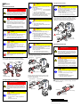
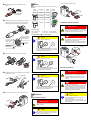
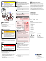
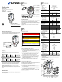
Description Position indication (visual) Connector (enclosed) Angle valve Technical Data Position indicator (electrical) pneumatically actuated bellows sealed with position indicator and pilot valve normally open Pneumatic actuator VAP016 … 040-A/X Control valve Pilot valve connection type nominal voltage power duty cycle nominal diameter Position indicator connection rating soldered joints 250 VAC / 25 VA / 0.1 A 50 VDC / 12.5 W / 0.25 A Connection flange Instant push-in fittings (enclosed) 2x 2x Vacuum connection DN 16 - 40 ISO-KF Functional principle Instruction Sheet Incl. Manufacturer's Declaration sima60e1-b When the pilot valve is activated, the angle valve is closed by the pressure spring. The position indicator is invisible. When the pilot valve is deactivated, the angle valve is opened by the pneumatic actuator. The green position indicator becomes visible. The final positions can be polled by the electrical position indicator. (0210) soldered joints normally open see product nameplate 1W 100% 0.42 mm DN 16 ISO-KF Actuation Compressed air supply tube connection pressure range (overpressure) piston displacement 5.5 cm3 12.1 cm3 26.2 cm3 Stroke of the valve plate 5 mm 10 mm 14 mm Conductance 1) 4.5 l/s 16 l/s 40 l/s 100 / min 100 ms 200 ms 100 / min 110 ms 290 ms 75 / min 150 ms 250 ms Switching frequency 2) Opening time 2) Closing time 2) ø4 mm, ø6 mm or ø¼“ 3 … 5 bar 3 … 6 bar Cycle life 3) 10 million Tightness 1×10⁻⁹ mbar l/s 1×10⁻⁸ mbar Pressure range max.(abs.) Symbols Used Product Identification In all communications with INFICON, please specify the information on the product nameplate. For convenient reference copy that information into the space provided below. DANGER Information on preventing any kind of physical injury. WARNING Information on preventing extensive equipment and environmental damage. Caution INFICON, FL - 9496 Balzers Typ: No: F-No: Information on correct handling or use. Disregard can lead to malfunctions or minor equipment damage. 20 Nominal voltage Dimensions in mm General Safety Instructions · Adhere to the applicable regulations and take the necessary precautions for the process media used. Validity This document applies to products with the following part numbers: Aluminum housing: DN 16 DN 25 ISO-KF ISO-KF DN 40 ISO-KF Nominal voltage (pilot valve) N.O. 250-206 250-246 24 VDC (=) Stainless steel housing: DN 16 DN 25 ISO-KF ISO-KF DN 40 ISO-KF 250-216 250-256 250-226 250-236 Consider possible reactions between the materials and the process media. · Adhere to the applicable regulations and take the necessary precautions for all work you are going to do and consider the safety instructions in this document. DN 40 ISO-KF opening: pneumatic closing: by pressure spring Pressure range min. Safety DN 25 ISO-KF Pressure difference Dp in closing direction in opening direction Opens to a pressure difference Dp 4) Temperatures ambiance bakeout housing aluminum stainless steel actuator / pilot valve 4 bar 2.5 bar 4 bar 2 bar 2 bar 1.5 bar 4 bar 2 bar 0 °C … 50 °C 80 °C 150 °C 50 °C Type of protection Protection class IP 50 according to DIN 40 050 II Installation angle Flow direction any any Materials housing aluminum stainless steel bellows / valve plate pressure spring DN 16 + 25 ISO-KF DN 40 ISO-KF seals shell / cylinder unit protective lids packing material Weight housing aluminum stainless steel 3.2572 1.4301 1.4541 / 1.4301 1.4301 1.1200 FPM PBTP PE carton box, PE, PU 0.3 kg 0.4 kg 0.44 kg 0.75 kg 0.9 kg 1.6 kg 1) For air with molecular flow · Before beginning to work, find out whether any vacuum components are contaminated. Adhere to the relevant regulations and take the necessary precautions when handling contaminated parts. 2) Nominal voltage (pilot valve) N.O. Communicate the safety instructions to all other users. 4) With pressure difference Dp=0 and compressed air = 5 bar (overpressure) Cycles without expendable parts (seals) and under clean operating conditions Compressed air = 5 bar (overpressure) 24 VDC (=) Liability and Warranty The part number can be taken from the product nameplate. If not indicated otherwise in the legends, the illustrations in this document correspond to the valve with the nominal diameter DN 25 ISO-KF. They apply to valves with other nominal diameters by analogy. We reserve the right to make technical changes without prior notice. Intended Use 3) Dimensions INFICON assumes no liability and the warranty becomes null and void if end-user or third parties · disregard the information in this document DN · use the product in a non-conforming manner · make any kind of interventions (modifications, alterations etc.) on the product · use the product with accessories and options not listed in the corresponding product documentation. M5 The end-user assumes the responsibility in conjunction with the process media used. 2x The angle valves are used as shut-off and venting devices for vacuum applications. 2x DN B C A DN DN 16 ISO-KF 154 127 71 DN 25 ISO-KF 176 147.4 92.5 DN 40 ISO-KF 196.5 167.3 112 D 60 74 98 E F G 51 100 40 63 108 50 83 120 65 Installation Compressed Air Outlet Caution Vacuum Connection Caution The compressed air must meet the following specifications: · free of particles >5 µm Skilled personnel The vacuum connection may only be established by persons who have suitable technical training and the necessary experience or who have been instructed by the end-user of the product. · DN 16 and DN 25: 3 … 5 bar overpressure DN 40: 3 … 6 bar overpressure · dry, free of oil or containing oil (keep using the same quality). If compressed air containing oil is used, dispose of the exhaust compressed air outlet in accordance with the relevant regulations. DANGER Caution: overpressure in the vacuum system >1 bar Injury caused by released parts and harm caused by escaping process gases can result if clamps are opened while the vacuum system is pressurized. Do not open any clamps while the vacuum system is pressurized. Use the type clamps which are suited to overpressure. Caution Contrary to the illustration below, the compressed air inlets and outlets of the following angle valves are reversed in position: Vacuum connection DN 40 ISO-KF and serial number (F-No) from · 101 for valve with aluminum housing · 118 for valve with stainless steel housing Screw in the enclosed instant push-in fitting for exhausting the compressed air if necessary. Push the tube into the instant push-in fitting until the mechanical stop is reached. Check that it is correctly mounted by slightly pulling. To ensure leak tightness of the instant push-in fitting · cut the plastic tube square · make sure the outside of the plastic tube is not damaged. Caution Caution Caution: dirt sensitive area Touching the product or parts thereof with one's bare hands increases the desorption rate. Always wear clean, lint-free gloves and use clean tools when working in this area. · use the enclosed instant push-in fitting (with extra-long thread) only. Tightening torque 0.5 Nm · screw in the instant push-in fitting without tilting it and without exceeding the tightening torque of 0.5 Nm. Compressed air inlet Compressed air outlet Compressed Air Inlet Caution Caution: vacuum component Dirt and damages impair the function of the vacuum component. When handling vacuum components, take appropriate measures to ensure cleanliness and prevent damages. Caution Contrary to the illustration below, the compressed air inlets and outlets of the following angle valves are reversed in position: Vacuum connection DN 40 ISO-KF and serial number (F-No) from · 101 for valve with aluminum housing Caution · 118 for valve with stainless steel housing Keep the protective lids and put them in place again when removing the product from the vacuum system. Remove the protective lids and install the valve to the vacuum system by means of the small flange fittings. Any installation angle and flow direction may be chosen. Clamp Caution: plastic thread The plastic thread is damaged by tilting or overturning the instant push-in fitting. Electrical Connection Skilled personnel The electrical connection, in accordance with the VDE 0100 guidelines, may be made only by a licensed electrician, qualified as per VDE 0105. The line cables shall be isolated from the line supply during all electrical work. If you wish to connect a ø6 mm, or ø¼“ plastic tube, exchange the instant push-in fitting. WARNING Compressed air inlet Compressed air outlet Seal with centering ring Caution: mains voltage The pilot valve can get destroyed if a wrong mains voltage is applied. The local mains power rating must correspond with the nominal voltage of the pilot valve (see product nameplate). If they do not correspond, exchange the pilot valve (® Furter information). Caution The cable must meet the following specifications: Tightening torque 0.5 Nm · flexible · conductor cross-section £0.75 mm2 · cable diameter £10 mm ISO-KF connection flange Protective lid Compressed Air Connection Insert the tube into the instant push-in fitting until the mechanical stop is reached. Check that it is correctly mounted by slightly pulling. Compressed air inlet Compressed air outlet · 6-pole without protective conductor or 7-pole with protective conductor. Preparing the connector Slide the screw fitting, connector housing, and strain relief on the cable. Skilled personnel Strain relief The compressed air connection may only be established by persons who have suitable technical training and the necessary experience or who have been instructed by the end-user of the product. Plastic tube Screw fitting Connector housing Seal Caution Washer Hex head screw Specifications for the plastic tube: · ø4 mm, ø6 mm or ø¼“ · bursting pressure ³ 10 bar overpressure (1 MPa) · material: PA soft or PU. s i ma 6 0 e 1 - b Original: German sima60d1-b (0210) (0210) Skin the cable and mount the insulating sleeves if required. Loosen the connector and unplug it. Operation The product is ready for operation as soon as it has been installed. Valve position closed Insulating sleeves (not incuded) Solder the cable. Slide the insulating sleeve over the soldered connections. The polarity of the pilot valve (solenoid coil) need not be taken into consideration. Compressed air Control valve available activated not available activated not available deactivated available deactivated Position indication open Compressed Air Connection Skilled personnel Pressure range: DN 16+25 ISO-KF: DN 40 ISO-KF -8 1×10 mbar … 4 bar (absolute) 1×10⁻⁸ mbar … 2.5 bar (absoute) The compressed air may only be disconnected by persons who have suitable technical training and the necessary experience or who have been instructed by the end-user of the product. Pressure difference Dp in closing direction Pilot valve (solenoid coil) Protective conductor Guide cam Caution Caution: pressure difference Dp p p Dp p + Dp V A P 0 25 Position indicator "valve open" DANGER Position indicator "valve closed" Closing direction bar bar Caution: compressed air Physical injury can result if a pressurized compressed air line is disconnected. Before doing any work, turn off the compressed air supply and relieve the compressed air lines. Pull out the tube while depressing the thrust ring. Thrust ring At Dp >4 bar (DN 16+25 ISO-KF) and Dp >2 bar (DN 40 ISO-KF) the valve may no longer be tight. Avoid bigger pressure differences. Tighten the strain relief and insert it (it will catch). Pressure difference Dp in opening direction Caution p p Dp p + Dp V A P 0 25 Opening direction Caution: pressure difference Dp bar bar With Dp >2 bar (DN 16+25 ISO-KF) and Dp >1.5 bar (DN 40 ISO-KF) the valve is opened. Avoid bigger pressure differences. Reassemble the connector and tighten the screw fitting (width across 17 mm). Skilled personnel Opening against a pressure difference Dp Caution hold stationary Caution: pressure difference Dp p The vacuum connection may only be disassembled by persons who have suitable technical training and the necessary experience or who have been instructed by the end-user of the product. Dp p + Dp V A P 0 25 Opening p Vacuum Connection bar bar With Dp >4 bar (DN 16+25 ISO-KF) and Dp >2 bar (DN 40 ISO-KF) the valve cannot open. Avoid bigger pressure differences. Plug in the connector and secure it with the union nut. Deinstallation Electrical Connection Skilled personnel The electrical power must be disconnected by a skilled electrician. Caution The control system must be disconnected from the power source before any connection to the product is made or interrupted. DANGER Caution: contaminated parts Contaminated parts can be detrimental to health. Before beginning to work, find out whether any parts are contaminated. Adhere to the relevant regulations and take the necessary precautions when handling contaminated parts. Caution Caution: vacuum component Dirt and damages impair the function of the vacuum component. When handling vacuum components, take appropriate measures to ensure cleanliness and prevent damages. Caution Caution: dirt sensitive area Touching the product or parts thereof with one's bare hands increases the desorption rate. Always wear clean, lint-free gloves and use clean tools when working in this area. Vent the vacuum system and disassemble the small flange connection. Place the protective lid. Declaration of Contamination Manufacturer's Declaration The service, repair, and/or disposal of vacuum equipment and components will only be carried out if a correctly completed declaration has been submitted. Non-completion will result in delay. This declaration may only be completed (in block letters) and signed by authorized and qualified staff. as defined by the Directive relating to machinery 98/37/EC, Appendix IIb Description of product Type Part number Serial number Reason for return Seal with centering ring We, INFICON, hereby declare that putting the incomplete equipment mentioned below into operation is not permitted until evidence is given that the system into which that incomplete equipment shall be installed is in accordance with the provisions of the EC Directive relating to machinery. We also declare that the equipment mentioned below complies with the provisions of the Directive relating to electrical equipment designed for use within certain voltage limits 73/23/EEC and the Directive relating to electromagnetic compatibility 89/336/EEC. Angle valve Clamp pneumatically actuated bellows sealed with position indicator and pilot valve normally open Operating fluid(s) used (Must be drained before shipping.) VAP016 … 040-A/X Used in copper process no q Protective lid Seal product in plastic bag and mark it with a corresponding label. yes q ISO-KF connection flange Process related contamination of product: Further information Refer to the Operating manual with regard to maintenance, repair, and spare parts. The Operating manual sina60e1 · can be downloaded from our website or · ordered at INFICON. Returning the product WARNING Caution: forwarding contaminated products Contaminated products (e.g. radioactive, toxic, caustic or microbiological hazard) can be detrimental to health and environment. Products returned to INFICON should preferably be free of harmful substances. Adhere to the forwarding regulations of all involved countries and forwarding companies and enclose a duly completed declaration of contamination. Products that are not clearly declared as "free of harmful substances" are decontaminated at the expense of the customer. Products not accompanied by a duly completed declaration of contamination are returned to the sender at his own expense. Disposal toxic corrosive biological hazard explosive radioactive other harmful substances no q 1) no q 1) no q no q no q no q 1) yes q yes q yes q 2) yes q 2) yes q 2) yes q 2) Products thus contaminated will not be accepted without written evidence of decontami nation. 1) or not containing any amount of hazardous residues that exceed the permissible exposure limits The product is free of any substances which are damaging to health. yes q Part numbers 250-206 250-216 250-226 250-236 250-246 250-256 Standards Harmonized and international/national standards and specifications: · EN 292-2 · DIN EN 60 204-1 · ISO 9803 · ISO 1609 · ISO 4414 · DIN 28 403 · DIN 28 404 · DIN 2501-1 · DIN 24 558 Harmful substances, gases and/or by-products Please list all substances, gases, and by-products which the product may have come into contact with: Trade/product name manufacturer Chemical name (or symbol) Precautions associated with substance Action if human contact Signatures INFICON AG, Balzers 22 October 2002 22 October 2002 Remo Klaiber Product Marketing Management Dr. Georg Sele Technical Support Manager Quality Representative Legally binding declaration: DANGER Caution: contaminated parts Contaminated parts can be detrimental to health and environment. Before beginning to work, find out whether any parts are contaminated. Adhere to the relevant regulations and take the necessary precautions when handling contaminated parts. We hereby declare that the information on this form is complete and accurate and that we will assume any further costs that may arise. The contaminated product will be dispatched in accordance with the applicable regulations. Organization/company Address Post code, place Phone Fax Email Name Company stamp Separating the components After disassembling the product, separate its components according to the following criteria: · Contaminated components Contaminated components (radioactive, toxic, caustic, or biological hazard etc.) must be decontaminated in accordance with the relevant national regulations, separated according to their materials, and disposed of. · Other components Such components must be separated according to their materials and recycled. This form can be downloaded from our website. Copies: Original for addressee 1 copy for accompanying documents 1 copy for file of sender LI–9496 Balzers Liechtenstein Tel +423 / 388 3111 Fax +423 / 388 3700 [email protected] www.inficon.com