1
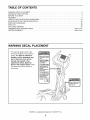
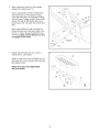
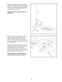
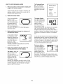
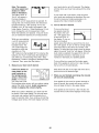
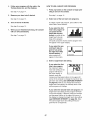
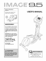
Model No, IMEL3906.0
Serial No,
USER'S MANUAL
Write the serial number in the
space above for reference.
oooo_
ooooo
Serial
.
'_
QUESTIONS?
As a manufacturer, we are committed to providing complete customer
satisfaction. If you have questions,
or if parts are damaged or missing,
PLEASE DO NOT CONTACT THE
STORE; please contact
Care.
Customer
IMPORTANT: You must note the
product model number and serial
number (see the drawing above)
before contacting us:
CALL TOLL-FREE:
1-800-753-4645
Mon,-Fri, 6 a,m,-6 p,m, MST
Sat, 8 a.m,-4 p.m, MST
ON THE WEB:
www.imageservice.com
www.imagefitness.com
new products, prizes,
fitness tips, and much more!
TABLE OF CONTENTS
WARNING DECAL PLACEMENT ..............................................................
IMPORTANT PRECAUTIONS
................................................................
BEFORE YOU BEGIN ......................................................................
ASSEMBLY ...............................................................................
HOW TO USE THE ELLIPTICAL EXERClSER ..................................................
MAINTENANCE AND TROUBLESHOOTING
...................................................
EXERCISE GUIDELINES ...................................................................
PART LIST ..............................................................................
EXPLODED DRAWING ....................................................................
ORDERING REPLACEMENT PARTS ..................................................
LIMITED WARRANTY ..............................................................
WARNING DECAL PLACEMENT
The warning decals shown here
have been applied in the locations
shown. If a decal is missing or
illegible, call the telephone number on the front cover of this
manual and request a free
replacement decal. Apply the
decal in the location shown. Note:
The decal may not be shown at
actual size.
IMAGE is a registered trademark of ICON IP, Inc.
2
2
3
4
5
12
24
25
28
30
Back Cover
Back Cover
IMPORTANT PRECAUTIONS
BEFORE
YOU
BEGIN
Thank you for selecting the new IMAGE _ 9.5 elliptical
exerciser. The iMAGE 9.5 is an incredibly smooth
exerciser that moves your feet in a natural elliptical
path, minimizing the impact on your knees and ankles.
Welcome to a whole new world of natural, ellipticalmotion exercise.
For your benefit, read this manual carefully before
you use the exercise cycle, If you have questions
after reading this manual, please see the front cover
of this manual. To help us assist you, note the product
model number and serial number before contacting
us. The model number and the location of the serial
number decal are shown on the front cover of this
manual.
To avoid a registration fee for any service needed
under warranty, you must register the elliptical
exerciser at www, imageservice,com/registration,
Before reading further, please familiarize yourself with
the parts that are labeled in the drawing below.
Fan
Console
I_
Upper Body Arm
Pulse Sensor
Water Bottle Holder
(no bottle is included)
Upright
Pedal Arm
Ramp
Wheel
Side Shield
Leveling Foot
Pedal Disk
Pedal
ASSEMBLY
To hire an authorized service technician to assemble the elliptical exerciser, call 1-800-445-2480.
Assembly requires two persons. Place all parts of the elliptical exerciser in a cleared area and remove all
packing materials; do not dispose of the packing materials until assembly is completed. Assembly requires the
included hex keys and your own adjustable
and rubber mallet c__
_J
wrench ___,
Phillips screwdriver _,
As you assemble the elliptical exerciser, use the drawings below to identify small parts. The number in parentheses below each drawing is the key number of the part, from the PART LIST near the end of this manual. The
number following the parentheses is the quantity needed for assembly. Note: Some small parts may have
been preassembled. If a part is not in the parts bag, check to see if it has been preassembled.
Star Washer
(85)-6
M8 Nylon
Locknut (87)-2
M8 Split
Washer (95)-2
M10 Nylon
Locknut (84)-4
M8 Washer
(64)-4
M4 x 16mm
Round Head
Screw (93)-4
M8 x 69mm Button Bolt (91)-2
M8 Large
Washer (81)-2
M4 x 19mm
Screw (68)-6
Wave Washer
(27)-2
M4 x 22mm
Screw (66)-2
Large Wave
Washer (20)-2
M8 x 25mm Patch
Screw (70)-6
M10 x 77mm Carriage Bolt (58)-4
M8 x 63mm Bolt Set (67)-2
1,
Attach the Rear Stabilizer (35) to the
Frame (1) with two M10 x 77mm Carriage
Bolts (58) and two M10 Nylon Locknuts (84).
Attach the Front Stabilizer (3) to the
Frame (1) with two M10 x 77mm Carriage
Bolts (58) and two M10 Nylon Locknuts (84).
58
3
84
6
.
Apply a generous amount of the included
grease to the Ramp Axle (74).
Have a second person hold the Ramp (78)
near the Frame (1) in the position shown.
Insert the Ramp Axle (74) through the Ramp
and the Frame. Tighten an M8 x 25mm Patch
Screw (70), with an M8 Washer (64) and a
Ramp Cover (59), into each end of the Ramp
Axle.
78
64
59
Next, pull the Ramp Pin (90) and align the
Ramp (78) with one of the three holes in the
Frame (1). Then, release the Ramp Pin into
the Frame. Make sure the Ramp Pin is firmly engaged in the Frame.
64
74
59
Identify the Left Pedal Arm (21), which is
marked with a "Left" sticker.
19
Attach a Pedal (19) to the Left Pedal Arm (21)
with three M4 x 19mm Screws (68) and three
Star Washers (85).
Repeat this step for the Right Pedal
Arm (not shown),
\
21
85
68
7
5.
Orient an Upper Body Leg (6) and a Ramp
Wheel (24) as shown. Attach the Upper Body
Leg and the Ramp Wheel to the Left Pedal
Arm (21) with an M8 x 63mm Bolt Set (67)
and two Wheel Covers (97).
5
Repeat this step for the Right Pedal Arm
(not shown),
j6
I
24
67
21
67
.
/
Grease
Apply a small amount of grease to a Crank
Arm Spacer (45). Orient the Crank Arm
Spacer so that the flange is on the side
shown, and slide it onto the Left Crank Arm
(42). Then, slide the Left Pedal Arm (21) onto
the Left Crank Arm.
Apply a small amount of grease to a Large
Wave Washer (20) and press it against the
Left Pedal Arm (21). Then, tighten an
M8 x 25mm Patch Screw (70) with an M8
Washer (64) and a Pedal Leg Cover (23) into
the end of the Left Crank Arm (42).
Repeat this step for the Right Pedal Arm
and the Right Crank Arm (not shown),
21
20
23
7,
Have a second person hold the Upright (2)
near the Frame (1) as shown. Next, connect
the Upper Wire Harness (18) to the Lower
Wire Harness (38).
Attach the Upright (2) to the Frame (1) with
two M8 x 69mm Button Bolts (91), two M8
Split Washers (95), and two M8 Nylon
Locknuts (87). Be careful to avoid pinching
the wires.
87
Attach the Water Bottle Holder (17) to the
Upright (2) with two M4 x 22mm Screws (66).
17
66
9
9.
The Console (10) requires four "D" batteries
(not included); alkaline batteries are recommended. IMPORTANT: If the elliptical exerciser has been exposed to cold temperatures, allow it to warm to room temperature before inserting batteries into the
Console. If you do not do this, the console
displays or other electronic components
may become damaged. Remove the battery
cover from the bottom of the Console and
9
11
93
insert four batteries into the battery compartment. Make sure the batteries are oriented
Console Wires
18
as shown by the diagram inside the battery
compartment.
Then, reattach the battery
cover.
Have a second person hold the Console (10)
near the Upright (2) as shown. Connect the
console wires to the Upper Wire Harness (18)
and the Pulse Wire (11). Attach the Console
(10) to the Upright (2) with four M4 x 16mm
Round Head Screws (93). Be careful to
avoid pinching the wires.
10. Identify the Left Upper Body Arm (4), which is
marked with a "Left" sticker. Orient the Left
Upper Body Arm so that the indicated tube is
facing inward.
10
Lubricate the upper end of the left Upper
Body Leg (6) using a small amount of the
included high-temperature lubricant. Then,
slide the Left Upper Body Arm (4) onto the
Upper Body Leg.
Apply a generous amount of grease to the
Pivot Axle (16). Then, insert the Pivot Axle
through the Left Upper Body Arm (4), an
Upper Body Arm Spacer (29), and the
Upright (2). Make sure the Upper Body Arm
Spacer is oriented as shown, with the
arrow pointed down.
29
Grease
_.
Lubricate
10
11. Orient the Right Upper Body Arm (5) so that
the indicated tube is facing inward. Lubricate
the upper end of the right Upper Body Leg (6)
with high-temperature lubricant. Then, slide
the Right Upper Body Arm onto the Upper
Body Leg.
11
Then, slide the Pivot Axle (16) through the
remaining Upper Body Spacer (29) and the
Right Upper Body Arm (5).
16\
Lubricate
12. Apply a small amount of grease to a Wave
Washer (27). Slide an M8 Large Washer (81)
and the Wave Washer onto an M8 x 25mm
12
//
Patch Screw (70), and tighten the Patch Screw
into the left end of the Pivot Axle (16). Then,
press a Pivot Cover (14) against the Left
Upper Body Arm (4).
14
Repeat this step on the right side of the
elliptical exerciser.
27
Grease
14
13. Make sure that all parts of the elliptical exerciser are properly tightened, Note: Some hardware may be
left over after assembly is completed. To protect the floor or carpet from damage, place a mat under the
elliptical exerciser.
11
HOW TO USE THE ELLIPTICAL
EXERCISER
HOW TO MOVE AND LEVEL THE ELLIPTICAL
EXERCISER
HOW TO EXERCISE ON THE ELLIPTICAL
EXERCISER
To move the elliptical exerciser, stand in front of it,
place one foot against one of the wheels, and firmly
hold the upper end of the upright. Pull the upright forward until you can move the elliptical exerciser on the
wheels. Carefully move the elliptical exerciser to the
desired location and then lower it. To decrease the
risk of injury, do not attempt to move the elliptical
exerciser over an uneven surface.
To mount the elliptical exerciser, firmly hold the upper
body arms and carefully step onto the pedal that is in
the lowest position. Next, step onto the other pedal.
Push the pedals until they begin to move with a continuous motion. Note: The pedal discs can turn in
either direction. It is recommended that you turn
the pedal discs in the direction shown below;
however, for variety, you can turn the pedal discs
in the opposite direction.
Upright
Upper
Pedal
Pedal
Disc
Leveling Foot
If the elliptical exerciser rocks slightly on your floor,
turn one or both of the leveling feet under the front
stabilizer until the rocking motion is eliminated.
HOW TO ADJUST THE RAMP INCLINE
The ramp has three
incline levels. To adjust
the incline level of the
ramp, pull the ramp pin,
move the ramp to the
desired incline level,
and engage the ramp
pin into one of the three
holes in the frame.
Ramp
To dismount the elliptical exerciser, allow the pedals to
come to a complete stop. The elliptical exerciser
does not have a freewheel; the pedals will continue to move until the flywheel stops, When the pedals are stationary, step off the higher pedal first. Then,
step off the lower pedal.
Frame
12
f_
ii[
20
minules
Note: If there is a sheet of clear plastic on the face
of the console, remove it before using the console.
l StepProgr,_ms
1StepResislance
Target Pace
Training
_7
ez, rformance
Too Fast
P_,rsonaI Training
On
Pace
Endurance
B:2
;"
Zones
Odometer
Aerobic
Fal Burn
lUUl
Start
m
Warm
5
Resistance
Toe Slow
Up
Cool Down
A WARNING:
TO reduce
aft insfru(
risk
of se,rious
lions
and
inlur_;
lh_
lead
warnings
m_d
und_
beh)re
FEATURES OF THE CONSOLE
sstxnd
us_?
users
m mu
K_,r,p d_Hdren
thu
away
d
(available at electronics stores), you can connect the
elliptical exerciser to your portable stereo, home
stereo, computer, or VCR and play special iFIT.com
CD and video programs (iFIT.com CDs and videocassettes are available separately), iFIT.com programs
automatically control the resistance of the pedals and
prompt you to vary your pace as a personal trainer
coaches you through every step of your workout.
High-energy music provides added motivation. To purchase iFIT.com COs and videocassettes,
call the
telephone number on the front cover of this manual.
The advanced console offers a selection of features
designed to make your workouts more enjoyable and
effective. When you use the manual mode of the console, you can change the resistance of the pedals with
the touch of a button. As you exercise, the console will
provide continuous exercise feedback. You can even
measure your heart rate using the handgrip pulse sensor.
The console also offers eight preset programs that
automatically change the resistance of the pedals and
prompt you to increase or decrease your pace while
guiding you through an effective workout.
With the elliptical exerciser connected to your computer, you can also go to our website at www.iFIT.com
and access programs directly from the Internet.
Explore www.iFIT.com for more information.
In addition, the console features two heart rate programs that automatically change the resistance of the
pedals and prompt you to vary your pace to keep your
heart rate near a target heart rate while you exercise.
To use the manual mode of the console, follow the
steps beginning on page 14. To use a preset program, see page 16. To use a heart rate program,
see page 17. To use an iFIT.com CD or video program, see page 22. To use an iFIT.com program
directly from our website, see page 23.
The console also features iFIT.com interactive technology. Having iFIT.com technology is like having a personal trainer in your home. Using a stereo audio cable
13
HOW TO USE THE MANUAL MODE
1.
The Training Zones
bar--The Training
Zones bar will show
Press any button on the console or begin pedaling to turn on the console.
Performance
the approximate intensity level of your exercise.
A few seconds after the console is turned on, the
displays will light. A tone will then sound and the
console will be ready for use.
2.
Warm
[]
[]
[]
[]
mmmmmm
[]
The upper display-The upper display will
show the approximate
number of grams of
carbs you have
burned, the approximate number of calo-
[]
[]
[]
U'UU
Aerobi
t
pedals by pressing the
Fat
B.I
1 Step Resistance butResistance
Warml
tons. Note: After you
Cool
press the 1 Step
Resistance buttons, it
will take a moment for the pedals to reach the
selected resistance level.
4.
Follow your progress with the matrix, the
Training Zones bar, and the displays.
The matrix--When
the
______
manual mode or the
[]
iFIT.com mode is
[]
[]
selected, the matrix will
display a track that
___
represents 1/4 mile
(400 meters). As you
exercise, the indicators around the track will
in succession until the entire track is lit. The
[]
[]
Up
Down
/I
Time1
"_
e
_ '_
ries you have burned, the distance you have pedaled, and the elapsed time. The display will
change modes every few seconds. Note: When a
program is selected, the display will show the time
remaining in the program instead of the elapsed
time.
Begin pedaling and change the resistance of
the pedals as desired.
As you pedal, change
the resistance of the
Aerobic
Cool
[]
[]
by pressing the iFIT
______
button once or twice
until a track appears in
the matrix; the letters "iFIT" should not appear
above the matrix.
3.
Endurance
Fat Burn
Select the manual mode.
If you have selected a
program or the
iFIT.com mode, reselect the manual mode
Training Zones
[]
[]
[]
To see the total distance that has been pedaled on
the elliptical exerciser, press the Odometer button
twice; the words "Total Dist." and the total number
of miles will appear in the display. To again see the
distance that you have pedaled during your workout, press the Odometer button again.
The lower display-The lower display will
show your pedaling
pace, in revolutions per
minute (RPM), your
pedaling speed, and
the resistance level of
tBul
Resistance
Warm
the pedals. The display will change modes every
few seconds. The display will also show your heart
rate when you use the handgrip pulse sensor.
light
track
will then disappear and the indicators will again
begin to light in succession.
14
1
Cool DJ
your heart rate for up to 30 seconds. The display
will then show your heart rate along with the other
modes.
Note: The console
J _ L,I L
F==g
can show speed and
distance in either
miles or kilometers.
The letters "MPH" or
"Km/H" will appear in
the lower display to
show which unit of measurement is selected. To
If your heart rate is not shown, make sure that
your hands are positioned as described. Be careful not to move your hands excessively or to
squeeze the metal contacts too tightly.
change the unit of measurement, first hold down
the Start button for a few seconds. An "E" (for
English) or an "M" (for metric) will appear in the
lower display. Press the 1 Step Resistance 10 button to change the unit of measurement. Note:
When the batteries are replaced, it may be necessary to reselect the desired unit of measurement.
While you are selecting
a unit of measurement,
you can also select a
backlight mode. The
"On" mode keeps the
backlight on while the
console is on. The
6.
To turn on the fan at
low speed, press the
Fan button; the number 1 will appear next
to the word "Fan" in
the display. To turn on
the fan at medium
L
m
2
m
[]
[]
[]
To turn off the fan, press the Fan button again.
Note: If the pedals do not turn for a few minutes,
the fan will turn off automatically.
Measure your heart rate if desired.
If there are sheets of
Slide the thumb tab on the right side of the fan to
pivot the fan to the desired angle.
clear plastic on the
metal contacts on
the handgrip pulse
Contacts_.,_t/_
sensor, remove the
plastic. To measure
your heart rate, hold
the handgrip pulse sensor, with your palms resting
against the metal contacts. Avoid moving your
hands or gripping the contacts tightly,
_n
immmmm
speed, press the button a second time; the number 2 will appear. To turn on the fan at high speed,
press the button a third time; the number 3 will
appear. To select the Auto mode, press the button
again; the words "Auto Fan" will appear. While the
Auto mode is selected, the speed of the fan will
automatically increase or decrease as you
increase or decrease your pedaling speed.
"Off" mode turns the backlight off. To conserve the
batteries, the "Auto" mode keeps the backlight on
only while you are exercising. Press the 1 Step
Resistance 1 button to change the backlight mode
if desired. Then, press the Start button.
5.
Turn on the fan if desired.
7.
I
When you are finished exercising, the console
will turn off automatically.
If the pedals do not move for several seconds, a
tone will sound, the console will pause, and the
time will begin to flash in the upper display.
If the pedals do not move for a few minutes, the
console will turn off and the displays will be reset.
When your pulse is detected, your heart rate will
be shown in the lower display. For the most accurate heart rate reading, hold the contacts for at
least 15 seconds. Note: If you continue to hold the
handgrip pulse sensor, the lower display will show
15
HOW TO USE A PRESET PROGRAM
1.
one of the "Too Fast" indicators lights, decrease
your pace; when the "On Pace" indicator lights,
maintain your current pace.
Press any button on the console or begin pedaling to turn on the console.
Target Pace
See step 1 on page 14.
Target Pace
Target Pace
Too Fast
Too Fast
On Pace
On Pace
Too Slow
Too Slow
Too Fast
2.
Select one of the eight preset programs,
To select a preset program, press one of the buttons labeled "20 minutes," "30 minutes," or "45
minutes." Note: Each "30 minutes" button can be
used to select two programs.
When a preset program is selected, a
profile of the resistance settings of the
program will scroll
across the matrix, tn
[]
m
STiti"l e
]
Resistance
addition, the program
time will appear in the upper display, and the maximum resistance setting of the program will flash in
the lower display for a moment.
3.
On Pace
A
Too Slow
(_
IMPORTANT: The pace settings are intended
only to provide motivation, Your actual pace
may be slower than the pace settings, Make
sure to exercise at a pace that is comfortable
for you.
U'UU
mmm
ira|
(_
When only three seconds remain in the first segment of the program, both the Current Segment
column and the column to the right will flash, a
series of tones will sound, and all resistance settings will move one column to the left. The resistance setting for the second segment will then be
shown in the flashing Current Segment column,
and the resistance of the pedals will change to the
resistance setting for the second segment. Note: If
all of the indicators in the Current Segment column
are lit after the resistance settings have moved to
the left, the resistance settings may move downward so only the highest indicators appear in the
matrix.
Press the Start button or begin pedaling to
start the program,
Each program is divided into several one-minute
segments. One resistance setting and one pace
setting are programmed for each segment. Note:
The same resistance setting and/or pace setting
may be programmed for two or more consecutive
segments.
The resistance setting for the first segment will be shown
The program will continue until the resistance setting for the last segment is shown in the Current
Segment column and the last segment ends.
Current Segment
m
m
in the flashing
mmmm
Current Segment
mmmmmm
|mmmmmmm
column of the
matrix. (The pace
settings are not
shown in the matrix.) The resistance settings for
the next several segments will be shown in the
columns to the right.
Note: During the program, you can override the
resistance setting for the current segment, if
desired, by pressing the 1 Step Resistance buttons. However, when the next segment begins, the
resistance will change if a different resistance setting is programmed for the next segment.
As you exercise, the Target Pace guide will help
you to keep your pedaling pace near the pace setting for the current segment. When one of the "Too
Stow" indicators lights, increase your pace; when
If you stop pedaling for several seconds, a tone
will sound and the program will pause. To restart
the program, simply resume pedaling.
16
4.
HOW TO USE A HEART RATE PROGRAM
Follow your progress with the matrix, the
Training Zones bar, and the displays.
1. Press any button on the console or begin pedaling to turn on the console.
See step 4 on page 14.
5.
Measure your heart rate if desired.
See step 1 on page 14.
See step 5 on page 15.
6.
2.
Turn on the fan if desired.
Select one of the two heart rate programs.
To select a heart rate program, press either of the
Heart Rate Control buttons.
See step 6 on page 15.
7.
When you are finished exercising,
will turn off automatically.
If you select the first
heart rate program (if
you press the left
Heart Rate Control
the console
See step 7 on page 15.
[]
[]
__
[]
__
__
___
__
_____
_________
__________
[]
button), a profile of the
target heart rate settings of the program
will scroll across the matrix and the program time
will appear in the upper display.
If you select the second heart rate program (if you press
the right Heart Rate
Control button), a
pulse symbol will
appear in the matrix.
3.
__
[]
[]
[]
Heart
[]
[]
_____
Rate
Enter a target heart rate setting.
If you select the first
heart rate program,
the maximum target
heart rate setting of the
ifU
[ ='"
"i v
program will flash in
the lower display. If
desired, press the
increase and decrease buttons in the upper left
corner of the console to change the maximum target heart rate setting (see EXERCISE INTENSITY
on page 25). Note: If you change the maximum
target heart rate setting, the intensity level of the
entire program will change.
u!
1
If you select the second heart rate program, the
target heart rate setting for the program will flash
in the lower display. If desired, press the increase
and decrease buttons in the upper left corner of
the display to change the target heart rate setting
(see EXERCISE INTENSITY on page 25). Note:
The same target heart rate setting will be programmed for all segments.
17
4.
Hold the handgrip pulse sensor.
ment. If your heart rate is too far below or above
the target heart rate setting, the resistance of the
pedals will automatically increase or decrease to
bring your heart rate closer to the target heart rate
setting.
It is not necessary to hold the handgrips continuously during the program. However, you should
hold the handgrips frequently for the program to
function properly. Each time you hold the handgrip pulse sensor, keep your hands on the
metal contacts for at least 30 seconds.
5.
The Target Pace guide will prompt you to increase
or decrease your pedaling pace during the program. When one of the "Too Slow" indicators
lights, increase your pace; when one of the "Too
Fast" indicators lights, decrease your pace; when
the "On Pace" indicator lights, maintain your current pace.
Press the Start button to start the program.
The first heart rate program--This
program is
divided into 30 one-minute segments. One target
heart rate setting is programmed for each segment. Note: The same target heart rate setting
may be programmed for two or more consecutive
segments.
The target heart rate
setting for the first
segment will be
shown in the flashing Current
Segment column of
the matrix. The tar-
IMPORTANT: The target heart rate settings are
intended only to provide motivation. Your actual heart rate may be slower than the target
heart rate settings. Make sure to exercise at a
pace that is comfortable for you.
CurrentSegment
Note: During the program, you can manually override the resistance setting for the current segment,
if desired, with the 1 Step Resistance buttons.
However, when the console compares your heart
rate to the target heart rate setting, the resistance
of the pedals may automatically increase or
decrease to bring your heart rate closer to the target heart rate setting.
[]
[]_
[]
__
__
___
__
___
_______
|_______
get heart rate settings for the next several segments will be shown
in the columns to the right.
When only three seconds remain in the first segment of the program, both the Current Segment
column and the column to the right will flash, a
series of tones will sound, and all target heart rate
settings will move one column to the left. The target heart rate setting for the second segment will
then be shown in the flashing Current Segment
column.
If you stop pedaling for several seconds, a tone
will sound and the program will pause. To restart
the program, simply resume pedaling.
.
Follow your progress with the matrix, the
Training Zones bar, and the displays.
See step 4 on page 14.
7.
The second heart rate program--This program
is divided into 40 one-minute segments. The same
target heart rate is programmed for all segments.
Note: For a shorter workout, stop exercising or
select a different program before the program
ends.
Turn on the fan if desired.
See step 6 on page 15.
.
Both heart rate programs--As
you pedal, the
console will regularly compare your heart rate to
the target heart rate setting for the current seg-
When you are finished exercising, the console
will turn off automatically.
See step 7 on page 15.
18
HOW TO CONNECT YOUR PORTABLE STEREO
HOW TO CONNECT YOUR CD PLAYER, VCR, OR
COMPUTER
Note: If your stereo has an RCA-type AUDIO OUT
jack, see instruction A below. If your stereo has a
1/8" LINE OUT jack, see instruction B. If your
stereo has only a PHONES jack, see instruction C.
To use iFIT, com CDs, the elliptical exerciser must be
connected to your portable CD player, portable stereo,
home stereo, or computer with CD player. See pages
19 and 20 for connecting instructions. To use
iFIT.com videocassettes,
the elliptical exerciser must
be connected to your VCR. See page 21 for connecting instructions. To use iFIT, com programs directly
from our website, the elliptical exerciser must be
connected to your computer. See page 20.
A.
Plug one end of a 1/8" to RCA stereo audio cable
(available at electronics stores) into the jack
beneath the console. Plug the other end of the
cable into the AUDIO OUT jack on your stereo.
HOW TO CONNECT YOUR PORTABLE CD PLAYER
Note: If your CD player has separate LINE OUT
and PHONES jacks, see instruction A below. If
your CD player has only one jack, see instruction
B.
A.
,r'_"_""
@, i............
_ ,_ i
I
E!,,-!!i!!ii
] [!!!!.,.11!
C.
a.
;_._I
Audio
U
e
d-
Plug one end of a 1/8" to 1/8" stereo audio cable
(available at electronics stores) into the jack
beneath the console. Plug the other end of the
cable into a 1/8" Y-adapter (available at electronics
stores). Plug the Y-adapter into the PHONES jack
on your CD player. Plug your headphones into the
other side of the Y-adapter.
See the drawing above. Plug one end of a 1/8" to
1/8" stereo audio cable (available at electronics
stores) into the jack beneath the console. Plug the
other end of the cable into the LINE OUT jack on
your stereo.
Plug one end of a 1/8" to 1/8" stereo audio cable
(available at electronics stores) into the jack
beneath the console. Plug the other end of the
cable into a 1/8" Y-adapter (available at electronics
stores). Plug the Y-adapter into the PHONES jack
on your stereo. Plug your headphones into the
other side of the Y-adapter.
C
o
o
i
__
Audio
Cable
1/8"_
Y-adapter
B- - 3_
i
Cable
}
Cable
a.
'_,....
a
Audio%_ A
Plug one end of a 1/8" to 1/8" stereo audio cable
(available at electronics stores) into the jack
beneath the console. Plug the other end of the
cable into the LINE OUT jack on your CD player.
Plug your headphones into the PHONES jack.
!
LEFT
Headphones
Y-adapter
Headphones_-_
19
_
HOW TO CONNECT YOUR HOME STEREO
HOW TO CONNECT YOUR COMPUTER
Note: If your stereo has an unused LINE OUT jack,
see instruction A below. If the LINE OUT jack is
being used, see instruction
B.
Note: If your computer has a 1/8" LINE OUT jack,
see instruction A. If your computer has only a
PHONES jack, see instruction B.
A.
Plug one end of a 1/8" to RCA stereo audio cable
(available at electronics stores) into the jack
beneath the console. Plug the other end of the
cable into the LINE OUT jack on your stereo.
A.
Plug one end of a 1/8" to 1/8" stereo audio cable
(available at electronics stores) into the jack
beneath the console. Plug the other end of the
cable into the LINE OUT jack on your computer.
A
Audio
Cable
iUNEO_
@ i
i
Audio
Cable
B.
B.
Plug one end of a 1/8" to RCA stereo audio cable
(available at electronics stores) into the jack
beneath the console. Plug the other end of the
cable into an RCA Y-adapter (available at electronics stores). Next, remove the wire that is currently
plugged into the LINE OUT jack on your stereo
and plug the wire into the unused side of the Yadapter. Plug the Y-adapter into the LINE OUT
jack on your stereo.
j
i
ooo
Plug one end of a 1/8" to 1/8" stereo audio cable
(available at electronics stores) into the jack
beneath the console. Plug the other end of the
cable into a 1/8" Y-adapter (available at electronics
stores). Plug the Y-adapter into the PHONES jack
on your computer. Plug your headphones or
speakers into the other side of the Y-adapter.
i PHONES
_)i
Audio
Cable
1/8"
Y-adapter
_® ........
He ad ph ones/S pea kers---_.-E:_:_
Audio
Cable
........
-,==_
RCA __
Y-adapter
_=_IZZ]_=_
......
Wire removed from -_-_=_
LINE OUT jack
2O
HOW TO CONNECT YOUR VCR
B,
Note: If your VCR has an unused AUDIO OUT jack,
see instruction A below. If the AUDIO OUT jack is
being used, see instruction B. If you have a TV
with a built-in VCR, see instruction B. If your VCR
is connected to your home stereo, see HOW TO
CONNECT YOUR HOME STEREO on page 20.
A,
Plug one end of a 1/8" to RCA stereo audio cable
(available at electronics stores) into the jack
beneath the console. Plug the other end of the
cable into an RCA Y-adapter (available at electronics stores). Next, remove the wire that is currently
plugged into the AUDIO OUT jack on your VCR
and plug the wire into the unused side of the Yadapter. Plug the Y-adapter into the AUDIO OUT
jack on your VCR.
Plug one end of a 1/8" to RCA stereo audio cable
(available at electronics stores) into the jack
beneath the console. Plug the other end of the
cable into the AUDIO OUT jack on your VCR.
t
i
=............
,'
Audio Cable
[25.
........
÷
/
z
,
'1
Wire removed from-_-E:_._
AUDIO OUT jack
Audio
Cable
21
HOW TO USE AN IFIT.COM CD OR VIDEO
PROGRAM
The program will function in almost the same way
as a preset program (see step 3 on page 16).
However, an electronic "chirping" sound will alert
you when the resistance setting and/or pace setting is about to change.
To use an iFIT.com CD or video program, the elliptical
exerciser must be connected to your CD player or
VCR. See HOW TO CONNECT YOUR CD PLAYER,
VCR, OR COMPUTER on pages 19 to 21. To purchase iFIT.com CDs or videocassettes, call the
telephone number on the front cover of this manual.
Note: If the resistance of the pedals and/or the
pace setting does not change when a "chirp"
sounds:
• Make sure that the letters "iFIT"
the matrix.
Follow the steps below to use an iFIT.com CD or
video program.
1.
• Adjust the volume of your CD player or VCR.
If the volume is too high or too low, the console may not detect the program signals.
Press any button on the console or begin pedaling to turn on the console.
• Make sure that the audio cable is properly
connected and that it is fully plugged in.
See step 1 on page 14.
2.
Select the iFIT.com mode.
.
To select the iFIT.com
mode, press the iFIT
button. A track will
appear in the matrix
and the letters "iFIT"
will appear above the
matrix.
3.
appear above
Follow your progress with the matrix, the
Training Zones bar, and the displays.
i FiT
[]
[]
m
VJ
[]
VJVJVJVJVJVJ
[]
[]
WJ
[]
[]
VJVJVJVJVJVJ
See step 4 on page 14.
5.
Measure your heart rate as desired.
See step 5 on page 15.
6.
Press the Play button on your CD player or
VCR.
Turn on the fan if desired.
See step 6 on page 15.
Note: If you are using an iFIT.com CD, insert the
CD into your CD player; if you are using an
iFIT.com videocassette, insert the videocassette
into your VCR.
7.
When you are finished exercising, the console
will turn off automatically.
See step 7 on page 15.
A moment after you press the play button, your
personal trainer will begin guiding you through
your workout. Simply follow your personal trainer's
instructions.
22
HOW TO USE PROGRAMS DIRECTLY FROM
OUR WEBSITE
6.
program.
Our website at www.iFIT.com allows you to play
iFIT.com programs directly from the Internet. To use
programs from our website, the elliptical exerciser
must be connected to your home computer. See HOW
TO CONNECT YOUR COMPUTER on page 20. In
addition, you must have an Internet connection and an
Internet service provider. A list of specific system
requirements is found on our website.
When you start the program, an on-screen countdown will begin.
7.
Return to the elliptical
pedaling.
exerciser
and begin
When the on-screen countdown ends, the program
will begin. The program will function in almost the
same way as a preset program (see step 3 on
page 16). However, an electronic "chirping" sound
will alert you when the resistance setting and/or
pace setting is about to change.
Follow the steps below to use a program from our
website.
1.
Follow the online instructions to start the
Press any button on the console or begin pedaling to turn on the console.
8.
Follow your progress with the matrix,
Training Zones bar, and the displays.
the
See step 1 on page 14.
See step 4 on page 14.
2.
Select the iFIT.com mode.
9.
Measure your heart rate if desired.
See step 2 on page 22.
See step 5 on page 15.
3.
Go to your computer and start an Internet
connection.
4.
Start your Web browser, if necessary, and go
to our website at www.iFIT.com.
5.
Follow the desired links on our website to
select a program.
10. Turn on the fan if desired.
See step 6 on page 15.
11. When you are finished exercising,
will turn off automatically.
See step 7 on page 15.
Read and follow the online instructions for using a
program.
23
the console
MAINTENANCE
AND TROUBLESHOOTING
HANDGRIP PULSE SENSOR TROUBLESHOOTING
Inspect and properly tighten all parts of the elliptical
exerciser regularly. Replace any worn parts immediately. The elliptical exerciser can be cleaned with a
soft cloth and mild detergent. Do not use abrasives
or solvents to clean the exerciser. To prevent damage to the console, keep liquids away from the console and keep the console out of direct sunlight.
If the handgrip pulse sensor does not function properly, make sure that your hands are positioned as
described in step 5 on page 15. Be careful not to
move your hands excessively or to squeeze the metal
contacts too tightly. For optimal performance, clean
the metal contacts using a soft cloth; never use alcohol, abrasives, or chemicals to clean the contacts.
When storing the elliptical exerciser, remove the batteries from the console. Keep the elliptical exerciser in
a clean, dry location, away from moisture and dust.
CONSOLE TROUBLESHOOTING
If the console does not function properly, the batteries
should be replaced. To replace the batteries, see
assembly step 9 on page 10.
24
EXERCISE GUIDELINES
Burning Fat--To burn fat effectively, you must exercise at a low intensity level for a sustained period of
time. During the first few minutes of exercise, your
body uses carbohydrate calories for energy. Only after
the first few minutes of exercise does your body begin
to use stored fat calories for energy, tf your goal is to
burn fat, adjust the intensity of your exercise until your
heart rate is near the lowest number in your training
zone. For maximum fat burning, exercise with your
heart rate near the middle number in your training
zone.
Aerobic Exercise--If your goal is to strengthen your
cardiovascular system, you must perform aerobic
exercise, which is activity that requires large amounts
of oxygen for prolonged periods of time. For aerobic
exercise, adjust the intensity of your exercise until
your heart rate is near the highest number in your
training zone.
These guidelines will help you to plan your exercise
program. For detailed exercise information, obtain a
reputable book or consult your physician. Remember,
proper nutrition and adequate rest are essential for
successful results.
WORKOUT
EXERCISE INTENSITY
Warming up--Start with 5 to 10 minutes of stretching
and light exercise. A warm-up increases your body
temperature, heart rate, and circulation in preparation
for exercise.
Whether your goal is to burn fat or to strengthen your
cardiovascular system, exercising at the proper intensity is the key to achieving results. You can use your
heart rate as a guide to find the proper intensity level.
The chart below shows recommended heart rates for
Training Zone Exercise--Exercise for 20 to 30 minutes with your heart rate in your training zone. (During
the first few weeks of your exercise program, do not
keep your heart rate in your training zone for longer
than 20 minutes.) Breathe regularly and deeply as you
exercise-never hold your breath.
fat burning and aerobic exercise.
165
155
145
140
130
125
215
145
138
130
125
120
115
125
118
110
103
110
105
95
90
20
30
40
50
60
70
GUIDELINES
_
<_
Cooling down--Finish
with 5 to 10 minutes of
stretching. Stretching increases the flexibility of your
muscles and helps to prevent post-exercise problems.
80
EXERCISE FREQUENCY
To find the proper intensity level, find your age at the
bottom of the chart (ages are rounded off to the nearest ten years). The three numbers listed above your
age define your "training zone." The lowest number is
the heart rate for fat burning, the middle number is the
heart rate for maximum fat burning, and the highest
number is the heart rate for aerobic exercise.
To maintain or improve your condition, complete three
workouts each week, with at least one day of rest
between workouts. After a few months of regular exercise, you may complete up to five workouts each
week, if desired. Remember, the key to success is to
make exercise a regular and enjoyable part of your
everyday life.
25
SUGGESTED
STRETCHES
The correct form for several basic stretches is shown at the right.
Move slowly as you stretch--never bounce.
1. Toe Touch Stretch
Stand with your knees bent slightly and slowly bend forward from
your hips. Allow your back and shoulders to relax as you reach
down toward your toes as far as possible. Hold for 15 counts,
then relax. Repeat 3 times. Stretches: Hamstrings, back of
knees, and back.
2. Hamstring Stretch
Sit with one leg extended. Bring the sole of the opposite foot
toward you and rest it against the inner thigh of your extended
leg. Reach toward your toes as far as possible. Hold for 15
counts, then relax. Repeat 3 times for each leg. Stretches:
Hamstrings, lower back, and groin.
3. Calf/Achilles Stretch
With one leg in front of the other, reach forward and place your
hands against a wall. Keep your back leg straight and your back
foot flat on the floor. Bend your front leg, lean forward, and move
your hips toward the wall. Hold for 15 counts, then relax. Repeat
3 times for each leg. To cause further stretching of the achilles
tendons, bend your back leg as well. Stretches: Calves, achilles
tendons, and ankles.
4. Quadriceps Stretch
With one hand against a wall for balance,
one foot with your other hand. Bring your
buttocks as possible. Hold for 15 counts,
times for each leg. Stretches: Quadriceps
reach back and grasp
heel as close to your
then relax. Repeat 3
and hip muscles.
26
1
NOTES
27
PART LIST--Model
Key No.
Qty,
1
1
2
3
No. IMEL3906.0
Description
Ro2o8A
Key No,
Qty.
Frame
41
1
1
Upright
Front Stabilizer
42
43
2
1
Crank Snap Ring
Left Crank Arm
4
5
6
7
8
9
10
11
1
1
2
2
2
2
1
2
Left Upper Body Arm
Right Upper Body Arm
Upper Body Leg
Sleeve
Foam Grip
Upper Body Endcap
Console
Pulse Sensor/Wire
44
45
46
47
48
49
50
51
1
1
2
1
1
Right Crank Arm
Resistance Cable
Crank Arm Spacer
Clamp
Reed Switch/Wire
12
13
14
2
1
2
Leveling Foot
Upright Endcap
Pivot Cover
52
53
54
15
16
17
18
19
6
1
1
1
2
Upper Body Bushing
Pivot Axle
Water Bottle Holder
Upper Wire Harness
Pedal
55
56
57
58
59
1
1
2
1
1
1
1
1
1
Flywheel
Flywheel Axle
Flywheel Bearing
"C" Magnet
"C" Magnet Bracket
Magnet
Spring
Idler
Resistance Motor
20
21
2
1
Large Wave Washer
Left Pedal Arm
60
61
2
4
4
7
1
Flange Screw
M10 x 77mm Carriage Bolt
Ramp Cover
M4 x 16mm Screw
M8 x 19mm Flat Head Bolt
22
23
24
25
26
27
1
2
2
4
4
2
Right Pedal Arm
Pedal Leg Cover
Ramp Wheel
Pedal Leg Bearing
Ramp Wheel Bushing
Wave Washer
62
63
64
65
66
67
28
29
30
2
2
1
Upright Spacer
Upper Body Arm Spacer
Left Side Shield
68
69
70
31
32
1
1
Right Side Shield
Left Disc
71
72
1
1
6
4
2
2
6
4
6
8
3
Adjustment
M6 x 18mm
M8 Washer
M5 x 16mm
M4 x 22mm
M8 x 63mm
M4 x 19mm
M4 x 12mm
M8 x 25mm
M5 x 25mm
M4 x 12mm
33
34
35
36
37
38
39
1
2
1
4
1
1
1
Right Disc
Disc Cover
Rear Stabilizer
Stabilizer Endcap
Belt
Lower Wire Harness
Crank
73
74
75
76
77
78
79
40
2
Crank Bearing
80
4
1
12
1
1
1
2
1
Ramp Bushing
Ramp Axle
M6 Star Washer
M6 x 38mm Bolt
M6 Nut
Ramp
Frame Bushing
M4 x 25mm Screw
28
Description
Screw
Bolt
Button Screw
Screw
Bolt Set
Screw
Screw
Patch Screw
Screw
Round Head Screw
Key No,
Qty.
81
82
83
84
85
86
87
88
89
90
2
4
1
7
6
2
4
2
2
1
Description
M8 Large Washer
M4 Washer
M6 Nylon Locknut
M10 Nylon Locknut
Star Washer
M4 x 20mm Screw
M8 Nylon Locknut
M10 x 60mm Button Bolt
Transport Wheel
Ramp Pin
Key No,
Qty.
91
92
93
94
95
96
97
*
*
*
2
2
4
2
2
2
4
-
Description
M8 x 69mm Button Bolt
M5 x 6mm Screw
M4 x 16mm Round Head Screw
M3 x 16mm Screw
M8 Split Washer
M4 Washer
Wheel Cover
Hex Key
Grease
User's Manual
Note: Specifications are subject to change without notice. See the back cover of this manual for information
about ordering replacement parts. *These parts are not illustrated.
29
EXPLODED DRAWING A--Model
No. IMEL3906.0
Ro2o8A
_9
13
_10
93
11
29
28
14
94
15
15
_66
92
15
29
_7
92
--6
19
97
%%
%%
%%%
22
19
7O
26
24
2O
25
67
25
97
21
68
70
30
EXPLODED DRAWING B--Model
No. IMEL3906.0
Ro2o8A
89
31
72
59
j
60
72
60
64
78
70
60
95
._84
63 76
91
87
34
53
77
59
74
@
64
47
49
44
45
54
84
33
43
71
75
71
36
\
\
\
\
37
34
\
\
\
\
31
ORDERING
REPLACEMENT
PARTS
To order replacement parts, please see the front cover of this manual. To help us assist you, be prepared to
provide the following information when contacting us:
• the model number and serial number of the product (see the front cover of this manual)
• the name of the product (see the front cover of this manual)
• the key number and description of the replacement part(s) (see the PART LIST and the EXPLODED
DRAWING near the end of this manual)
LIMITED WARRANTY
ICON Health & Fitness, tnc. (ICON) warrants this product to be free from defects in workmanship and
material, under normal use and service conditions, for a period of ninety (90) days from the date of purchase. This warranty extends only to the original purchaser. ICON's obligation under this warranty is limited to replacing or repairing, at ICON's option, the product through one of its authorized service centers.
All repairs for which warranty claims are made must be pre-authorized by ICON. If the product is shipped
to a service center, freight charges to and from the service center will be the customer's responsibility. For
in-home service, the customer will be responsible for a minimal trip charge. This warranty does not extend
to any product or damage to a product caused by or attributable to freight damage, abuse, misuse,
improper or abnormal usage or repairs not provided by an ICON authorized service center; products used
for commercial or rental purposes; or products used as store display models. No other warranty beyond
that specifically set forth above is authorized by ICON.
ICON is not responsible or liable for indirect, special or consequential damages arising out of or in connection with the use or performance of the product or damages with respect to any economic loss, loss
of property, loss of revenues or profits, loss of enjoyment or use, costs of removal or installation or other
consequential damages of whatsoever nature. Some states do not allow the exclusion or limitation of incidental or consequential damages. Accordingly, the above limitation may not apply to you.
The warranty extended hereunder is in lieu of any and all other warranties and any implied warranties of
merchantability or fitness for a particular purpose is limited in its scope and duration to the terms set forth
herein. Some states do not allow limitations on how long an implied warranty lasts. Accordingly, the above
limitation may not apply to you.
This warranty gives you specific legal rights. You may also have other rights which vary from state to state.
ICON HEALTH & FITNESS, INC., 1500 S. 1000 W., LOGAN, UT 84321-9813
Part No. 245513 R0208A
Printed in China © 2008 ICON IP, Inc.