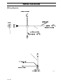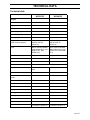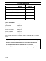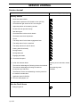
1
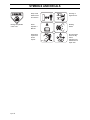
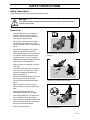
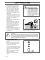
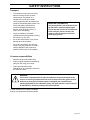
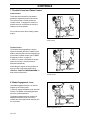
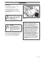
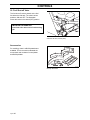
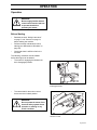
Operator´s manual WG4815E/968999120 WG3613E/968999117 Please read the operator’s manual carefully and make sure you understand the instructions before using the machine. English OPERATOR’S MANUAL MOWER WG3613E WG4815E Contents Contents ..................................................................1 Introduction ............................................................3 Congratulations ...................................................3 General ...............................................................3 Driving and Transport on Public Roads ..............3 Towing ................................................................3 Operating ............................................................3 Good Service ......................................................4 Manufacturing Number .......................................4 Symbols and Decals ..............................................5 Safety Instructions .................................................7 General Use ........................................................7 Driving on Slopes ................................................9 Children .............................................................10 Maintenance .....................................................11 Transport ...........................................................13 Customer responsibilities ..................................13 Controls ................................................................14 Control Locations ..............................................14 1. Recoil Starter Grip ........................................15 2. Ignition Switch ...............................................15 3. Motion control levers .....................................16 4. Operator Presence Levers ............................16 5. Gear shift lever ..............................................17 6. Neutral Bail ...................................................17 7. Throttle Control and Choke Control ..............18 8. Blade Engagement Lever .............................18 9. Refueling .......................................................19 10. Fuel Shut-off Valve .....................................20 Accessories .......................................................20 Operation ..............................................................21 Before Starting ..................................................21 Starting the Engine ...........................................22 Gearbox ............................................................25 Running .............................................................25 Reversing ..........................................................26 To operate on hills ............................................26 Mowing Tips .....................................................26 Stopping ............................................................28 Stopping the Engine ..........................................29 Adjustment of cutting height ..............................30 Moving machine by Hand .................................33 Maintenance ........................................................ 34 Maintenance Schedule ..................................... 34 Ignition System ................................................. 36 Checking the Safety System ............................ 37 Checking the Engine's Cooling Air Intake ........ 38 Replacing the Air Filter ..................................... 39 Replacing the Fuel Filter .................................. 40 Checking the Fuel Pump’s Air Filter ................. 40 Checking Tire Pressures .................................. 40 Checking the Parking Brake ............................. 41 Checking the V-belts ........................................ 41 Checking the Blades ........................................ 42 Brake Rod Adjustment ..................................... 42 Under side of rear deck .................................... 42 Cleaning and Washing ..................................... 43 Caster Wheels .................................................. 43 Hardware .......................................................... 43 Blade replacement ........................................... 44 Lubrication ........................................................... 45 Lubrication Schedule ........................................ 45 General ............................................................ 45 Lubricating the Cables ..................................... 46 Lubricating in Accordance with the Lubrication Schedule .......................................................... 46 Trouble Shooting Guide ..................................... 51 Storage ................................................................. 53 Winter Storage ................................................. 53 Service ............................................................. 53 Wiring diagrams .................................................. 54 Technical data .................................................... 55 Torque Specifications ....................................... 56 Conformity Certificates ....................................... 57 USA requirements ............................................ 57 Service Journal .................................................. 58 Delivery Service ............................................... 58 After the First 8 Hours ...................................... 58 25-Hour Service ............................................... 59 50-Hour Service ............................................... 60 100-Hour Service ............................................. 61 300-Hour Service ............................................. 62 At Least Once Each Year ................................. 63 English-1 WARNING! Failure to follow safe operating practices can result in serious injury to the operator or other persons. The owner must understand these instructions, and must allow only trained persons who understand these instructions to operate the mower. Each person operating the mower must be of sound mind and body and must not be under the influence of any mind altering substance. WARNING! Engine exhaust, some of its constituents, and certain vehicle componets contain or emit chemicals known to the State of California to cause cancer and birth defects or other reproductive harm. English-2 INTRODUCTION Introduction Congratulations Thank you for purchasing a Husqvarna Walk-Behind Mower. This machine is built for the greatest efficiency and rapid mowing primarily of large areas. Controls in one place and a transmission regulated by steering controls contribute to the machine’s performance. This manual is a valuable document. Following the instructions (use, service, maintenance, etc.) can considerably increase the lifespan of your machine and even increase its resale value. If you sell your machine, be sure to give this Operator’s Manual to the new owner. The final chapter of this Operator’s Manual comprises a Service Journal. Ensure that service and repair work is documented. A well kept service journal reduces service costs for the season-based maintenance and affects the machine’s resale value. Take the Operator’s Manual along when the machine is left to the workshop for service. General In this Operator’s manual, left and right, backward and forward are used in relation to the machine’s normal driving direction. Driving and Transport on Public Roads Check applicable road traffic regulations before driving and transport on public roads. If the machine is transported, you should always use approved fastening equipment and ensure that the machine is well anchored. Towing Do not tow this machine, it may cause damage to the drive system. Do not tow any trailers, etc. with this mower. They may jackknife or overturn causing damage to the mower and possibly serious injury to the operator. Operating This machine is constructed only for mowing grass on lawns and other free and level ground without obstacles such as stones, tree stubs, etc. The machine can also be used for other tasks when equipped with special accessories provided by the manufacturer, for which the operating instructions are provided in conjunction with delivery. All other types of use are incorrect. The manufacturer’s directions concerning operation, maintenance, and repairs must be carefully followed. Lawnmowers and all power equipment, can be potentially dangerous if used improperly. Safety requires good judgement, careful use in accordance with these instructions and common sense. The machine must only be operated, maintained, and repaired by persons that are familiar with the machine’s special characteristics and who are well versed in the safety instructions. Accident prevention regulations, other general safety regulations, occupational safety rules, and traffic regulations must be followed without fail. Unauthorized modifications to the design of the machine may absolve the manufacturer from liability for any resulting personal injury or property damage. English-3 INTRODUCTION Good Service Husqvarna’s products are sold all over the world and only in specialized retail stores with complete service. This ensures that you as a customer receive only the best support and service. Before the product is delivered, the machine has, for example, been inspected and adjusted by your retailer, see the certificate in the Service Journal in this Operator’s Manual. When you need spare parts or support in service questions, warranty issues, etc., please consult the following professional: This Operator’s Manual belongs to the machine with manufacturing number: Engine Transmission Manufacturing Number The machine’s manufacturing number can be found on the printed plate of the rear part of the chassi. Stated on the plate, from the top are: • The machine’s type designation (I.D.). • The manufacturer's type number (Model). • The machine’s serial number (Serial no.) Please state the type designation and serial number when ordering spare parts. The engine’s manufacturing number is stated on a barcode decal. This is placed on the left side of the crankcase. The plate states: • The engine’s serial number (E/NO). • The engine’s type designation (Code). Please state these when ordering spare parts. English-4 SYMBOLS AND DECALS Symbols and Decals These symbols are found on the machine and in the operator’s manual. Study them carefully so that you know what they mean. WARNING! Xxxxxxx xxxx xxxxxxxx xxx x Xxxxx xxxxxx xx. xx xxxxxxxx xxxxx xxx xx. Used in this publication to notify the reader of a risk of personal injury, particularly if the reader should neglect to follow instructions given in the manual. IMPORTANT INFORMATION Xxxxxxx xxxx xxxxxxxx xxx xxx xxxx xxxxxx xx. Used in this publication to notify the reader of a risk of material damage, particularly if the reader should neglect to follow instructions given in the manual. Used also when there is a potential for misuse or misassembly. Warning! Noise emissions to the surroundings in accordance with the European Union’s directive. The machine’s emission is stated in the chapter TECHNICAL DATA and on the decals. Slow Fast CE conformity marking Only machines for European market. Choke Warning! Rotating blades, keep away from the discharge deck Use protective glasses Use protective gloves Fuel Do not touch rotating parts Do not stand here English-5 SYMBOLS AND DECALS Moving sharp blades under cover English-6 Keep a safe distance from the machine. Severing of fingers & toes. Read Operator´s Manual. Rotating blades Whole body exposure to thrown objects. Shut off engine & remove key before performing any maintenance or repair work. SAFETY INSTRUCTIONS Safety Instructions These instructions are for your safety. Read them carefully. WARNING! This symbol means that important safety instructions need to be emphasized. It concerns your safety. General Use • Read all instructions in this operator’s manual and on the machine before starting it. Ensure that you understand them and then abide by them. • Learn how to use the machine and its controls safely and learn how to stop quickly. Also learn to recognize the safety decals. • Only allow the machine to be used by adults who are familiar with its use. • Make sure nobody else is in the vicinity of the machine when you start the engine, engage the drive, or run the machine. • Make sure animals and people maintain a safe distance from the machine. • Stop the machine if someone enters the work area. • Clear the area of objects such as stones, toys, steel wire, etc. that may become caught in the blades and thrown out before operating unit. • Beware of the discharge deck and do not point it at any one. Do not use the machine without the discharge chute in place. 8011-630 • Stop the engine and prevent it from starting before you clean the discharge deck. • Remember that the operator is responsible for dangers or accidents. • Never take passengers. The machine is only intended for use by one person. • Always look down and behind before and during reversing maneuvers. Look out for both large and small obstacles. • Slow down before turning. Read the operator’s manual before starting the machine 8011-631 Clear the area of objects before mowing 8011-632 Never take passengers English-7 SAFETY INSTRUCTIONS • Shut off the blades when not mowing. • Be careful when turning around fixed objects, so that the blades do not hit them. Never drive over foreign objects. • Only use the machine in daylight or in other well-lit conditions. Keep the machine a safe distance from holes or other irregularities. Pay attention to other possible risks. • Never use the machine if you are tired, if you have consumed alcohol, or if you are taking other drugs or medication that can affect your vision, judgment, or coordination. • Beware of traffic when working near or crossing a road. • Never leave the machine unsupervised with the engine running. Always shut down the blades, engage the parking brake if so equipped, stop the engine, and remove the ignition key before leaving the machine. • Never allow children or other persons not trained in the use of the machine to use or service it. Local laws may regulate the age of the user. WARNING! Engine exhaust and certain vehicle components contain or emit chemicals considered to cause cancer, birth defects, or other reproductive system damage. The engine exhaust contains carbon monoxide, which is a colorless, poisonous gas. Do not use the machine in enclosed spaces. 8011-633 Keep children away from the work area WARNING! When using the machine, approved personal protective equipment should be used. Personal protective equipment cannot eliminate the risk of injury but it will reduce the degree of injury if an accident does happen. Ask your retailer for help in choosing the right equipment. • Make sure that you have first aid equipment close at hand when using the machine. • Never use the machine when barefoot. Always wear protective shoes or boots, preferably with steel toecaps. • Always wear approved protective glasses or a full visor when assembling or driving. • Always wear gloves when handling the blades. • Never wear loose clothing that can get caught in moving parts. • Use ear protectors to avoid impaired hearing. English-8 8011-670 Personal protective equipment SAFETY INSTRUCTIONS Driving on Slopes Driving on slopes is one of the operations where the risk is greatest that the driver will lose control or the machine will tip over, which can result in serious injury or death. All slopes require extra caution. If you cannot reverse up a slope or if you feel unsure, do not mow the slope. Do as follows • Remove obstacles such as stones, tree branches, etc. • Watch out for and avoid driving over furrows, holes, and bumps. On uneven terrain, the machine can tip more easily. Long grass can hide obstacles. • Mow up and down, not side-to-side. • If machine stops while going uphill, disengage blades and back down slowly. • Drive evenly and slowly. Use small movements of the steering controls. • Be extra cautious with any additional equipment, which can alter the machine’s stability. 8011-634 Mow up and down, not side-to-side Do not • Do not make sudden changes in speed or direction. • Do not drive the machine on terrain that slopes more than 10°. • Do not mow near verges, ditches, or banks. The machine can suddenly spin around if a wheel goes over the edge of a drop or ditch, or if an edge gives way. • Do not mow wet grass. It is slippery, and the tires can lose their grip, so that the machine slides. • Avoid unnecessary turns on slopes, and if it proves necessary, turn slowly and gradually downward, if possible. • 8011-635 Be extra cautious when driving on slopes Avoid starting or stopping on a slope. If the tires begin to slip, shut off the blades and drive slowly straight down the slope. English-9 SAFETY INSTRUCTIONS Children • Serious accidents may occur if you fail to be on guard for children in the vicinity of the machine. Children are often attracted to the machine and mowing work. Never assume that children will stay where you last saw them. • Keep children away from the mowing area and under close supervision by another adult. • Keep an eye out and shut off the machine if children enter the work area. • Before and during a reversing maneuver, look backward and downward for small children. • Never allow a child to ride with you. They can fall off and injure themselves seriously or prevent risk-free maneuvering of the machine. • Never allow children to operate the machine. • Be particularly cautious near corners, bushes, trees, or other objects that block your view. 8011-636 English-10 Never allow children to operate the machine SAFETY INSTRUCTIONS Maintenance WARNING! The engine must not be started when the protective plate for the mower deck’s drive belt is removed. • Stop the engine. Prevent the engine from starting by removing the spark plug cables from the spark plugs or by removing the ignition key before making any adjustments or performing maintenance. • Never fill the fuel tank indoors. • Fuel and fuel fumes are poisonous and extremely flammable. Be especially cautious when handling fuel, as carelessness can result in personal injury or fire. • Only store fuel in containers approved for the purpose. • Never remove the fuel tank cap and never fill the fuel tank while the engine is running. • Allow the engine to cool before refueling. Do not smoke. Do not fill fuel in the vicinity of sparks or open flames. • If leaks arise in the fuel system, the engine must not be started until the problem has been resolved. • Store the machine and fuel in such a way that there is no risk of leaking fuel or fuel vapor leading to damages. • Check the fuel level before each use and leave space for the fuel to expand, because the heat from the engine and the sun may otherwise cause the fuel to expand and overflow. • Avoid overfilling. If you spill fuel on the machine, wipe up the spill and wait until it has evaporated before starting the engine. If you have spilled fuel on your clothing, change your clothing. • Allow the machine to cool before taking any actions in the engine compartment. • Ensure that nuts and bolts, especially the fastening bolts for the blade attachments, are properly tightened and that the equipment is in good condition. 8011-637 Never fill the fuel tank indoors WARNING! The engine, the exhaust system components become very warm during operation. Risk for burns if touched. 8011-777 Do not smoke when using machine. English-11 SAFETY INSTRUCTIONS • Do not modify safety equipment. Check regularly to be sure it works properly. The machine must not be driven with defective or unmounted protective plates, protective cowlings, safety switches, or other protective devices. • Do not change the settings of governors and avoid running the engine with overly high engine speeds. If you run the engine too fast, you risk damaging the machine components. • Never use the machine indoors or in spaces lacking proper ventilation. The exhaust fumes contain carbon monoxide, an odorless, poisonous, and lethal gas. • Stop and inspect the equipment if you run over or into anything. If necessary, make repairs before starting. • Never make adjustments with the engine running. • The machine is tested and approved only with the equipment originally provided or recommended by the manufacturer. • The blades are sharp and can cause cuts and gashes. Wrap the blades or use protective gloves when handling them. • Check the parking brake’s functionality regularly. Adjust and service as necessary. • When mowing in familiar areas use the mulch deck. • Reduce the risk of fire by removing grass, leaves, and other debris that may have accumulated on the machine. Allow the machine to cool before putting it in storage. • Have your mower inspected and serviced each year by an authorized Husqvarna dealer. • Use only authentic Husqvarna replacement parts to insure that the safety and quality of your mower is maintained. • Safety decals should be replaced if they are missing or illegible. Decals can be purchased from your Husqvarna dealer. 8011-638 Never drive the machine in an enclosed space Use protective glasses at maintenance work. 8011-639 Clean the machine regularly English-12 SAFETY INSTRUCTIONS Transport • The machine is heavy and can cause serious crushing injuries. Be extra cautious when it is loaded on or unloaded from a vehicle or trailer. • Use an approved trailer to transport the machine. Activate the parking brake, turn off the fuel supply, and fasten the machine with approved fastening devices, such as bands, chains, or ropes, when transporting. • Check and abide by local traffic regulations before transporting or driving the machine on any road. • Do not tow this machine, it may cause damage to the drive system. • Do not tow any trailers, etc. with this mower. They may jackknife or overturn causing damage to the mower and possibly serious injury to the operator. IMPORTANT INFORMATION The parking brake is not sufficient to lock the machine in place during transport. Ensure that the machine is well fastened to the transport vehicle. Reverse the machine onto the transport vehicle to avoid tipping it over. Customer responsibilities • Read and observe the safety rules. • Follow a regular schedule in maintaining, caring for and using your mower. • Follow the instructions under "Maintenance” and "Storage” sections of this owner’s manual. WARNING! This mower is equipped with an internal combustion engine and should not be used on or near any unimproved forest-covered, bush-covered or grass-covered land unless the engine’s exhaust system is equipped with a spark arrester meeting applicable local or state laws (if any). If a spark arrester is used, it should be maintained in effective working order by the operator. A spark arrester for the muffler is available through your authorized Husqvarna dealer. English- 13 CONTROLS Controls This operator’s manual describes the Husqvarna Walk-Behind Mowers WG3613E and WG4815E. The machines are fitted with a Kawasaki four-stroke V-Twin engine, for data see “Technical data” on page 55. Transmission from the engine is made via two V-belt, one for each wheel. Using the left and right motion controls, the speed of the rear wheels is regulated for steering of the machine. 8011-473 Walk behind mower 8011-776 Locations of the controls Control Locations Page Page 1. Recoil starter grip 15 6. Neutral bail 17 2. Ignition switch 15 7. Throttle control and choke control 18 3. Motion control levers 16 8. Blade engagement lever 18 4. Operator presence levers 16 9. Fuel cap 19 5. Gear shift lever 17 10. Fuel shut-off valve 20 English-14 CONTROLS 1. Recoil Starter Grip IMPORTANT INFORMATION Do not let recoil cord snap back by itself. This may damage the cord or the recoil starter assembly. Pull the recoil starter grip slowly until you feel compression, then pull it briskly. Normally this engine will not backfire. If you get backfires, contact your Husqvarna dealer for service. 8011-476 Recoil starter grip 2. Ignition Switch The ignition key switch is placed on the control panel. 8011-475 Ignition key English- 15 CONTROLS 3. Motion control levers The machine’s speed and direction are continuously variable using the two motion control levers. When both controls are in the neutral position, the machine stands still. The controls can be locked in neutral position by the Neutral bail By moving both controls an equal amount the machine moves in a straight line forward. WARNING! The machine can turn very rapidly if one steering control is moved much further than the other. 8011-478 Motion controls levers In order, for example, to turn right while moving forward, move the right control towards the handle (neutral position). The rotation of the right wheel is reduced and the machine turns to the right. To stop forward travel pull levers back. 4. Operator Presence Levers Located on the handle. As an additional safety feature, these mowers are equipped with an Operators Presence System. This is an electrical interlock safety system which is activated by depressing either one or both of the Operator Presence Levers at the handle grips. Releasing both Operators Presence Levers while mowing or transporting will break the electrical circuit and cause the engine and mower to stop. The mower will not stop immediately after releasing the O.P. levers, some travel does occur. One or both levers must be pressed against the handle for the engine to remain running, when the blades are engaged or neutral lock bail is not locked in drive levers. English-16 8011-683 Operator presence levers CONTROLS 5. Gear shift lever Gear shift lever has 5 gears speed. There is also a neutral gear and reverse gear. Grip motion control levers before shifting gears. This will clutch the gearbox. 8011-482 Gear drive lever in neutral position 6. Neutral Bail Keeps the unit from moving while idling. The neutral bail will lock the drive levers in neutral position and must be activated when starting the engine. Parking Brake The parking brake on geardrive machines is applied when neutral bail is in lock position. 8011-477 Neutral bail English- 17 CONTROLS 7. Throttle Control and Choke Control Choke Control The choke control is used for cold starts to provide the engine with a richer fuel mixture. The choke control is combined with the Throttle control. To engage the choke, the throttle control is moved past the max rpm setting to its choke position. Do not use the choke when starting a warm engine. 8011-682 Choke control Throttle Control The throttle control regulates the engine speed and thereby the rate of rotation of the blades, assuming the control for engaging the mower deck is pulled forward, see “8. Blade Engagement Lever” on page 18. In order to increase or decrease the engine speed, the control is moved forward or backward respectively. Avoid idling the engine for long periods, as there is a risk of the spark plugs fouling. USE FULL THROTTLE WHEN MOWING, for best mower performance. 8011-682 Throttle control 8. Blade Engagement Lever The blade engagement lever is on the left support by the control panel. In order to engage the blades, push the lever forward. The blades are disengaged when the lever is pulled backward. The blade engagement lever needs to be adjusted so the lever does not come in contact with control panel when the lever is in the off position. 8011-474 Blade engagement lever English-18 CONTROLS 9. Refueling The machine has one fuel tank. The tank volume is 5.3 gallons / 20 liters. The engine should be run on a minimum of 87-octane unleaded gasoline (no oil mix). Also see Technical Data concerning methanol and ethanol fuels. WARNING! Gasoline is highly flammable. Observe caution and fill the tank outdoors (see the safety rules). 8011-418 Fuel tank IMPORTANT INFORMATION . WARNING! Fill to bottom of filler neck. Do not overfill. Wipe off any spilled oil or fuel. Do not store, spill or use gasoline near an open flame. When operating in temperatures below 32° F. (0° C.), use fresh, clean winter grade gasoline to help insure good cold weather starting. Experience indicates that alcohol blended fuels (called gasohol or using ethanol or methanol) can attract moisture which leads to separation and formation of acids during storage. Acidic gas can damage the fuel system of an engine while in storage. To avoid engine problems, the fuel system should be emptied before storage of 30 days or longer. Drain the gas tank, start the engine and let it the run until the fuel lines and carburetor are empty. Use fresh fuel the next season. See Storage Instructions for additional information. Never use engine or carburetor cleaners in the fuel tank or permanent damage may occur. English- 19 CONTROLS 10. Fuel Shut-off Valve The fuel shut-off valve is placed on the fuel line below the fuel tank. The valve has two positions; ON and OFF. The illustration shows the valve in the closed (OFF) position. IMPORTANT INFORMATION Close fuel valve at the end of each mowing job. 8011-437 Fuel shut off valve, closed (OFF) Accessories For mulching, there is a BioClip attachment available. This is mounted underneath the mower deck and consists of control plates and BioClip blades. 8011-566 BioClip attachment English-20 OPERATION Operation WARNING! Be thoroughly familiar with all controls their function and how to operate them before operating the mower. Before Starting • Read the sections “Safety Instructions” on page 7, and “Controls” on page 14, before starting the machine. • Perform the daily maintenance before starting (see “Maintenance Schedule” on page 34). • Check that there is sufficient fuel in the fuel tank. The following conditions must be fulfilled before the engine can be started: • The control for engaging the blades must be in disengaged position. 8011-474 Disengaged blades • The neutral bail for the motion control levers must be in locked position. WARNING! Do not operate the mower if the interlock safety system allows operation or starting in any unsafe condition. 8011-477 Neutral lock bail English- 21 OPERATION Starting the Engine WARNING! Never run the engine indoors, in enclosed or poorly ventilated spaces. Engine exhaust fumes contain poisonous carbon monoxide. 1. Move blade engagement lever to the OFF position, so the interlock will allow engine to start. 8011-474 Blade engagement lever 2. Check gear shifter to be sure it is in the neutral position. 8011-482 Gear shifter 3. While on level terrain, squeeze both motion control levers and lift up on the neutral bail to lock it into the neutral lock position. This will ensure that the mower is braked. 8011-477 Neutral bail in neutral lock position English-22 OPERATION 4. Open fuel shut-off valve. 8011-438 Fuel shut-off valve, Open 5. Turn ignition key to ON position. 8011-475 Ignition key 6. Set throttle control and engage the choke (if needed). Do not use choke when the engine is warm. IMPORTANT INFORMATION Do not let recoil cord snap back by itself. This may damage the cord or the recoil starter assembly. 8011-682 Choke and Throttle controls 7. Pull the recoil starter grip slowly until you feel compression, then pull it briskly. If the engine won´t start in three pulls, open the choke and try again. 8011-476 Pull the starter grip English- 23 OPERATION 8. Warm engine momentarily, then disengage the choke until engine runs smoothly, approximately 1/2 throttle. WARNING! Be sure all persons are clear of area before engaging the blades. IMPORTANT INFORMATION To prolong spindle bearing clutch and belt life engage and disengage blades at approximately ½ throttle. 9. Depress one operator presence lever. Engage the blades and set the desired rpm. The best cutting and bagging is obtained with engine at top rpm. Grip motion control levers before shifting gears. 8011-683 Presence lever 8011-474 Blade engaged English-24 OPERATION Gearbox The gear drive machines have a 5-speed gearbox. The gear selector is placed under the control panel. Only shift gear when the machine is standing still and on level ground. 8011-482 Gear selector Running 1. Depress one operator presence lever and shift transmission to the desired gear. 2. Unlock the motion control levers by pushing the neutral bail down out of the neutral slots. Slowly release both levers at the same time to begin forward motion. 3. The steering system of this mower uses individual right and left motion control levers on the handle bars. Squeezing the lever will reduce tension on the wheel drive belt eliminating power to that wheel. With the opposite wheel still under power a turn is accomplished. 4. If the motion control lever is squeezed even tighter the brake will be applied to that wheel and a tighter more abrupt turn is accomplished. - turn left by squeezing the left hand lever or turn right by squeezing the right hand lever. If you squeeze both levers the mower will stop. 8011-403 1. Operator Presence Lever 2. Drive Lever 3. Neutral Bail 4. Handle E-handle with bail in neutral position English- 25 OPERATION Reversing Depress one operator presence lever and shift transmission to the reverse gear. Grip motion control levers before shifting gear. 8011-482 Clutch drive before shifting gear To operate on hills To operate on slopes is a dangerous mowing job. Read the Safety Instructions section “Driving on Slopes” on page 8. WARNING! Do not drive up or down hills with slopes greater than 10 degrees. And do not drive across any slopes. • The slowest speed possible should be used before starting up or down hills. • Avoid stopping or changing speed on hills. • Make all turns slowly. Mowing Tips • Observe and mark rocks and other fixed objects in order to avoid collisions. • The cutting deck should be properly leveled for best mowing performance. The blades should be parallel to the ground or slightly tipped down in the front. • Only use sharp blades. • Check tire pressure. Different pressure can cause uneven mowing results. • The left hand side of the deck should be used for trimming. English-26 WARNING! Clear the lawn of stones and other objects that can be thrown out by the blades. OPERATION • Drive so that clippings are discharged onto the area that has been cut. Have the cut area to the right of the mower. This will result in more even distribution of clippings and a more uniform cut. To avoid clippings spraying on roads etc, mow the first two patterns in opposite direction. • Begin with a high cutting height and reduce it until the desired mowing result is attained. The average lawn should be cut to 2 1/2" (64 mm) during the cool season and to over 3" (76 mm) during the hot months. For healthier and better looking lawns, mow often after moderate growth. 8011-409 Mowing patterns For best cutting performance, grass over 15 cm (6") in height should be mowed twice. Make the first cut relatively high; the second to the desired height. • The mowing result will be best with a high engine speed (the blades rotate rapidly) and low speed (the machine moves slowly). If the grass is not too long and dense, the driving speed can be increased without noticeably depreciating the mowing result. • The finest lawns are obtained by mowing often. The mowing becomes more even and the grass clippings more evenly distributed over the mown area. The total time taken is not increased as a higher driving speed can be used without poorer mowing results. • Avoid mowing wet lawns. The mowing result is poorer because the wheels sink into the soft lawn, clumps build, and the grass clippings will fasten under the cowling. English- 27 OPERATION • Hose the mower deck with water after each use. Hose especially underneath. Do not spray high pressure spray directly on top of spindles. • Avoid getting engine too wet. WARNING Never drive the machine on terrain that slopes more than 10o. Mow slopes up and down, never side-to-side. Avoid sudden directional changes. 8011-514 Clean mower deck after each use Stopping Emergency stop Release both hands from the operate presence lever handles. When both operator presence levers return to their outer position, the engine will quit and the mower will stop. or Pull both drive levers firmly against handle grips and hold them securely in place. Use thumbs to lift the neutral bail up into the neutral slot. Then stop engine by pulling throttle control back and shut off the key switch. Normal operating stop 1. Pull both drive levers (traction levers) firmly toward the handle grips to stop forward motion. 2. Use thumbs to lift neutral bail into the neutral slots. 3. Move the throttle control to the slow position. 4. Move blade engagement control to the off position. 5. Move shift lever to the neutral position. 6. Stop engine, refer to “Stopping the Engine” on page 29. English-28 IMPORTANT INFORMATION Close fuel valve at the end of each mowing job. OPERATION Stopping the Engine Allow the engine to idle a minute in order to attain normal operating temperature before stopping it, if it has been worked hard. Avoid idling the engine for longer periods, as there is a risk of the spark plugs fouling. 1. When the machine is standing still, set the neutral bail in the lock position. 8011-477 Parking brake 2. Disengage the blades by pulling the blade egagement lever back. 8011-474 Disengage the blades 3. Move the throttle to the minimum position (tortoise symbol). Turn the ignition key to the stop position. 4. Remove the ignition key. 8011-475 Ignition key 5. Shut OFF the fuel valve. IMPORTANT INFORMATION Close fuel valve at the end of each mowing job. 8011-437 Fuel valve English- 29 OPERATION Adjustment of cutting height The cutting height can be adjusted by three methods: • Moving spacers between the upper side and the lower side of the caster swivel according to "Cutting height table". For instruction, see below. • Moving spacers between the upper side and the lower side of the blades according to "Cutting height table". For removing and installation of blades, refer to “Blade replacement” on page 44. • Rear axle height adjustment according to the following instruction. 1. To adjust rear axle, stop engine and place motion control levers in the neutral lock position, remove spark plug wires. 2. Remove lower belt shield from underside of rear deck for better access to axle adjustment bolts. 3. Loosen axle pivot bolts and axle adjustment bolts. See illustration. 1. Axle pivot bolt 4. Place a jack under center of rear deck, raise the jack slightly so axle adjustment bolts may be removed. A-D. Axle adjustment bolts 8011-408 5. With the jack, raise or lower the rear deck to the desired position using the chart to ensure proper height. 6. Reinstall the axle adjustment bolts and tighten. A tapered punch may be used to help align the holes. 7. Using the "Cutting height table", find the correct number of spacers to be placed under the caster swivel. 8. Remove the lynch pin and washer from the top of the caster and reposition spacers to the desired cutting height from the table. See illustration. 2. Securing bolts (Loosen each side) Rear axle height adjustment IMPORTANT INFORMATION It may be necessary to readjust drive and brake linkages. 8011-405 IMPORTANT INFORMATION 1. Machinery bushing To achieve the best quality cut, the blades should be level with the ground or slightly tipped forward. 2. Caster swivel English-30 3. ½" "C" Spacers Caster height adjustment OPERATION Cutting height table Axle position A Spacers below caster arm 0 1 B 2 3 Blade spacers under cutter housing Cutting height 4 1 1/2" (38 mm) 3 1 3/4" (44 mm) 2 2" (51 mm) 1 2 1/4" (57 mm) 0 2 1/2" (64 mm) 4 1 3/4" (44 mm) 3 2" (51 mm) 2 2 1/4" (57 mm) 1 2 1/2" (64 mm) 0 2 3/4" (70 mm) 4 2 1/2" (64 mm) 3 2 3/4" (70 mm) 2 3" (76 mm) 1 3 1/4" (83 mm) 0 3 1/2" (89 mm) 4 3" (76 mm) 3 3 1/4" (83 mm) 2 3 1/2" (89 mm) 1 3 3/4" (95 mm) 0 4" (102 mm) English- 31 OPERATION Axle position C Spacers below caster arm 3 4 D 4 5 English-32 Blade spacers under cutter housing Cutting height 4 3 1/4" (83 mm) 3 3 1/2" (89 mm) 2 3 3/4 (95 mm) 1 4" (102 mm) 0 4 1/4" (108 mm) 4 3 1/2" (89 mm) 3 3 3/4" (95 mm) 2 4" (102 mm) 1 4 1/4" (108 mm) 0 4 1/2" (114 mm) 4 3 3/4" (95 mm) 3 4" (102 mm) 2 4 1/4" (108 mm) 1 4 1/2" (114 mm) 0 4 3/4" (121 mm) 4 4" (102 mm) 3 4 1/4" (108 mm) 2 4 1/2" (114 mm) 1 4 3/4" (121 mm) 0 5" (127 mm) OPERATION Moving machine by Hand In order for the machine to be moved with the engine turned off, make sure the gear shift lever is in the neutral position and the motion control levers are not in the locked position. The locked position is used when the machine is parked. 8011-482 Gear shift lever in neutral position English- 33 MAINTENANCE Maintenance Maintenance Schedule The following is a list of maintenance procedures that must be performed on the machine. For those points not described in this manual, visit an authorized service workshop. An annual service carried out by an authorized service workshop is recommended in order to maintain your machine in the best possible condition and to ensure safe operation. Read Safety Instructions section “Maintenance” on page 10. z = Described in this manual = Not described in this manual Daily maintenance Maintenance Weekly At mainte- least nance once each Page Before After year - Check the parking brake 41 z Check the engine’s oil level (every refueling) 47 z Front and rear tires 40 z Check the fuel pump’s air filter 40 Check the safety system 37 Check/clean the engine’s cooling air intake 38 Check the cutting deck 42 Check underside of rear deck 42 z Check hardware (screws, nuts, etc.) 43 z - Clean under the mower deck 43 z Inspect/Replace blades 2) 44 Check the condition of belts, belt pulleys, etc. 41 Check for fuel and oil leakages Start the engine and blades, listen for unusual sounds Check for damage Check the tire pressures - 25 50 100 z z z z z z z z z z 40 Thoroughly clean around the engine - Clean around belts, belt pulleys, etc. - English-34 Maintenance interval in hours 300 MAINTENANCE Daily maintenance Weekly At mainte- least nance once each Page Before After year Maintenance Check/adjust the cutting height Maintenance interval in hours 25 50 100 300 - Linkages and adjustments 43 z Check throttle and choke cables 46 z Clean the air cleaner’s pre-filter (foam) 39 z Clean the air cleaner’s filter cartridge 2) (paper filter) 39 z Change the engine oil 1) 67 z z Replace the engine oil filter (every 200 hours) 47 z z Clean/Replace the spark plugs 36 z z Replace the fuel filter 40 z z - - Replace the air cleaner’s pre-filter (foam) 39 z z Replace the air filter (paper filter, every 200 hours) 2) 39 z Check the caster wheel bolt (every 200 hours) 43 Lubricate according to Lubrication Schedule 65 Perform the 300-hour service 4) 95 Check/adjust the parking brake - Clean the cooling fins Check the engine valve clearance4) z z z z z z z z z z z 1) First change after 8 hours. When operating with a heavy load or at high ambient temperatures, replace every 50 hours. 2) In dusty conditions, cleaning and replacement are required more often. 3) For daily use, the machine should be lubricated twice weekly. 4) Performed by authorized service workshop. z = Described in this manual = Not described in this manual WARNING! No adjustments or maintenance to be carried out unless: • The engine is stopped. • The ignition key has been removed. • The parking brake is on. English- 35 MAINTENANCE Ignition System The engine is equipped with an electronic ignition system. Only the spark plugs require maintenance. For recommended spark plugs, see Technical Data. 1. 2. Remove the ignition cable boot and clean around the spark plug. Remove the spark plugs with a spark plug socket wrench. 3. Check the spark plugs. Replace the spark plug if the electrodes are burned or if the insulation is cracked or damaged. Clean the spark plug with a steel brush if it is to be reused. 4. Measure the electrode gap with a gapping tool. The gap should be 0.030” (0.75 mm). Adjust as necessary by bending the side electrode. 5. Reinsert the spark plugs, turning by hand to avoid damaging the threads. 6. After the spark plug is seated, tighten it using a spark plug wrench so that the washer is compressed. Used spark plugs should be turned 1/8 of a turn from the seated position. New spark plugs should be turned 1/4 of a turn from the seated position. 7. Connect the ignition cable. English-36 IMPORTANT INFORMATION Fitting the wrong spark plug type can damage the engine. Inadequately tightened spark plugs can cause overheating and damage the engine. Tightening the spark plugs too hard can damage the threads in the cylinder head. 8011-054 Measure the electrode gap MAINTENANCE Checking the Safety System The machine is equipped with a safety system that prevents starting or driving under the following conditions. The engine can only be started when: 1. The blades are disengaged. 2. The neutral bail must be in the locked position. Make daily inspections to ensure that the safety system works by attempting to start the engine when one of the conditions is not met. If the machine starts when one of these conditions is not met, turn the machine off and repair the safety system before using the machine again. 8011-477 Condition for starting Functional check Check the function of the safety electrical system on a regular basis. 1. Engine must stop if blades are engaged without operator presence levers held down. 2. Engine must stop if transmission is taken out of neutral without holding down operator presence levers. 3. Engine must not start unless blades are off and transmission is in the neutral position. WARNING! Do not operate the mower if the interlock safety system allows operating or starting in any unsafe condition. English- 37 MAINTENANCE Checking the Engine's Cooling Air Intake Check that the engine’s cooling air intake is free from leaves, grass, and dirt. If the cooling air intake is clogged, engine cooling deteriorates, which can lead to engine damage. 8011-783 Check and clean the cooling air intake Checking and Adjusting the Throttle and Choke Cable Check that the engine responds to throttle increases and that a good engine speed is attained at full throttle. If doubts arise, contact the Husqvarna service workshop. If adjustments are necessary, they can be made as follows for the cable: 1. Loosen the clamping screw for the cable’s outer casing. 2. Check that the throttle cable is mounted in the correct hole in the lever. 3. Set the throttle lever at full throttle with no choke. 4. Align the hole in the speed control lever with the hole in the base plate by moving the lever. Insert a 6 mm dia pin (or a screw) through the two holes. 5. Pull up the outer housing of the throttle cable until the inner wire has almost no slack and tighten the clamping screw. 6. Remove the 6 mm pin. 7. Make sure that the carburetor choke valve is closed completely when the throttle lever is moved to choke position. 8. Check engine idle speed. 8011-485 English-38 Adjusting the throttle cable MAINTENANCE Replacing the Air Filter If the engine seems weak or runs unevenly, the air filter may be clogged. If run with a dirty air filter, the spark plugs can become fouled disrupting operation. For this reason, it is important to replace the air filter regularly (see the heading Maintenance Schedule for the proper service interval). Cleaning/replacing the air filter is carried out as follows: 8011-486 Remove the air filter cowling WARNING! Allow the exhaust system to cool before performing service. Risk for burns. 1. Depress the two tabs. 2. Remove the air filter cowling. 3. Remove the paper filter. 4. Remove the foam pre-filter and clean using a mild detergent. Squeeze it dry with a clean cloth 8011-487 Remove the paper filter IMPORTANT INFORMATION Do not used compressed air to clean the air filter. Do not wash the paper filter. Do not oil the paper filter. 5. Refit the air filter as follows: Check that the paper filter is whole. 8011-488 Remove the pre-filter Mount the pre-filter under the paper filter. Mount the paper filter in the air filter cowling. 6. Install the filter cowling on the air filter housing. 8009-450 Remove dust English- 39 MAINTENANCE Replacing the Fuel Filter Replace the line-mounted fuel filter every 100 hours (once per season) or more regularly if it is clogged. Replace the filter as follows: 1. Move the hose clamps away from the filter. Use flat-nosed pliers. 2. Pull the filter loose from the hose ends. 3. Push the new filter into the hose ends. Position the filter with the ”FLOW” arrow pointing up toward the fuel pump. If necessary, a soap solution can be applied to the filter ends to ease mounting. 4. 8011-425 Fuel filter Move the hose clamps back toward the filter. Checking the Fuel Pump’s Air Filter Regularly check that the fuel pump’s air filter is free from dirt. Remove the screws and open the pump, no hoses need be removed. The filter can be cleaned with a brush if necessary. Replace the filter on the bracket. 8009-147 The fuel pump’s air filter Checking Tire Pressures All four tires should have a pressure of 15 PSI (1 bar). 8011-564 Tire pressures English-40 MAINTENANCE Checking the Parking Brake Visually check that no damage is found on the neutral bail. Perform a test drive and check that there is sufficent braking action. To adjust the handbrake, contact the service workshop if you are uncertain. Set the neutral bail in the neutral lock position. Tighten the wing nut. Check if the machine is braked, if not tighten the wing nut again. 8011-477 The neutral bail in locked position Checking the V-belts Deck belt Check every 100 hours of operation. Check for severe cracking and large nicks. NOTE: The belt will show some small cracks in normal operation. To replace belt lower the deck to its lowest position. Remove the plate and belt shields. Use a ratchet with a 9/16” socket on the spring idler bolt to relieve the tension on the belt. Slide the belt off of pulley and fully remove the belt. 8011-775 Slackening the belt tensioner Reverse the proceedure for installation. See the decal on the top of deck for belt routing information. After installation is complete check the belt for twists. English- 41 MAINTENANCE Checking the Blades In order to attain the best mowing effect, it is important that the blades are well sharpened and not damaged. : Bent or cracked blades or blades with large nicks must be replaced. Check the blade mounts. IMPORTANT INFORMATION The replacement or sharpening of blades should be carried out by an authorized service workshop. Damaged blades should be replaced when hitting obstacles that result in a breakdown. Let the service workshop decide whether the blade can be repaired/ground or must be replaced. 8011-604 Check the blades WARNING! Blades are sharp. Protect your hands with gloves and/or wrap blades with a heavy cloth when handling. Brake Rod Adjustment 1. Make sure the rod is installed into the proper hole in the brake arm. The brake rod should be in the lower hole on the brake arm. 2. To increase braking, turn the wing nut down on the rod. Do not turn the wing nut down too far as this will result in a constant braking action and will excessively wear the brake lining and cause premature failure. 8011-774 Brake rod position Under side of rear deck Remove grass and debris. English-42 MAINTENANCE Cleaning and Washing Regular cleaning and washing, especially under the mower deck, will increase the machine’s lifespan. Make it a habit to clean the machine directly after use, before the dirt sticks. Do not spray high pressure water directly on the top of the deck. 8011-639 Cleaning Caster Wheels Check every 200 hours. Lift front of unit off of ground so caster wheels can rotate freely. Tighten caster bolt (34) then back off 1/2 turn. Check that wheel rotates freely. If wheel does not rotate freely, back the caster bolt off in 1/4 turn increments until wheel rotates freely. IMPORTANT INFORMATION DO NOT add any type of tire liner or foam fill material to the tires. Excessive loads created by foam filled tires will cause premature failures. 8011-619 Caster wheels Only use O.E.M. specified tires. Foam filled tires or solid tires will void the warranty. Hardware Check daily. Inspect the entire machine for loose or missing hardware. English- 43 MAINTENANCE Blade replacement WARNING! Blades are sharp. Protect your hands with gloves and/or wrap blades with a heavy cloth when handling. • Remove blade bolt by turning counterclockwise. IMPORTANT INFORMATION To ensure proper assembly, center hole in blade must align with star on cutter housing. • • Install new or re-sharpened blade with stamped “GRASS side” facing towards ground/grass (down) or “THIS SIDE UP” facing deck and cutter housing. Install and tighten blade bolt securely. Tighten torque 90 ft/lb (122 Nm). IMPORTANT INFORMATION Special blade bolt is heat treated. Replace with a Husqvarna bolt if required. Do NOT use lower grade hardware than specified. English-44 8011-671 1. Blade 2. Center hole 3. Star 4. Cutter housing 5. Blade bolt (special) Blade attachment, principal LUBRICATION Lubrication Lubrication Schedule 12/12 1/52 1/365 25h 50h 100h 200h 300h 8011-685 Lubrication schedule 12/12 Every year Lubricate with grease gun 1/52 Every week Oil change Lubricate with oil can Level check 1/365 Every day Filter change General Remove the ignition key to prevent unintentional movements during lubrication. When lubricating with an oil can, it should be filled with engine oil. When lubricating with grease, unless otherwise stated, use a high grade molybdenum disulfide grease or another chassis or ball bearing grease offering good corrosion protection should be used. For daily use, the machine shall be lubricated twice weekly. Wipe away excess grease after lubrication. It is important to avoid getting lubricant on the belts or the drive surfaces on the belt pulleys. Should this happen, attempt to clean them with spirits. If the belt continues to slip after cleaning with spirits, it must be replaced. Gasoline or other petroleum products must not be used to clean belts. English- 45 LUBRICATION Lubricating the Cables If possible, lubricate both ends of the cables and move the controls to end stop positions when lubricating. Refit the rubber covers on the cables after lubrication. Cables with sheaths will bind if they are not lubricated regularly. If a cable binds, it can disrupt operation. If a cable binds, remove the cable and hang it vertically. Lubricate it with thin engine oil until the oil begins to escape from the bottom. Hint!: Fill a small plastic bag with oil and tape it so that it seals against the sheath and allow the cable to hang vertically from the bag overnight. If you do not succeed in lubricating the cable, it must be replaced. Lubricating in Accordance with the Lubrication Schedule 1. Front Wheel Mount Lubricate with a grease gun, one zerk for each wheel mount, until the grease is forced out. Use only good quality molybdenum disulphide grease. Grease from well-known brand names (petrochemical companies, etc.) usually maintains a good quality. 8011-573 Lubricating the front wheels 2. Front Wheel Bearings Lubricate with a grease gun, one zerk for each set of wheel bearings, until the grease is forced out. Use only good quality molybdenum disulphide grease. 3. Throttle and Choke Cable, Lever Bearings Lubricate the cable end at the carburetor with the oil can. Move the controls to the end points and lubricate again. The throttle cable is also lubricated at the control when the control console is removed. 8011-485 Throttle and choke cable by the carburetor English-46 LUBRICATION 4. Changing the Oil Filter 1. Drain the engine oil in accordance with the description in Engine Oil/Change Engine Oil. 2. Disassemble the oil filter. If necessary, use a filter remover. 3. Wipe new, clean engine oil on the seal of the new filter. 4. Mount the filter by hand with + 3/4 turn. 5. Run the engine warm, then check that there are no leaks around the oil filter seal. 6. 8011-785 Changing the oil filter Check the oil level in the engine, fill if necessary. The oil filter holds 0.2 qt (0.2 liters) of oil. 5. Engine oil Changing the Engine Oil The engine oil should be changed for the first time after 8 hours of operation. Thereafter, it should be changed every 100 hours. IMPORTANT INFORMATION WARNING! Engine oil can be very hot if it is drained directly after stopping the engine. Allow the engine to cool somewhat first. 1. Place the machine on a flat surface. 2. Place a container under the engine where the hose from the oil drain valve exits. 3. Remove the dipstick and open the drain valve. 4. Allow the oil to run out into the container. 5. Then close the oil drain valve. 6. Replace the oil filter if necessary. 7. Fill with new engine oil, Refer to “Checking the Oil Level” on page 48. 8. Start the engine. Run it for a few seconds and re-check the oil level. Used engine oil is a health hazard and must not be disposed of on the ground or in nature; it should always be disposed of at a workshop or appropriate disposal location. Avoid skin contact; wash with soap and water in case of spills. 8011-451 Oil drain valve English- 47 LUBRICATION Checking the Oil Level Check the oil level in the engine when the machine is standing level and the engine is stopped. Remove the dipstick, wipe it clean, and then replace it. The dipstick should not be screwed into place. Take the dipstick out again and read the oil level. 8011-452 Remove the dipstick The oil level should lie between the markings on the dipstick. If the level is approaching the ”ADD” mark, fill with oil to the ”FULL” mark on the dipstick. Never fill above the ”FULL” mark. The oil is filled through the hole for the dipstick. 8009-159 The dipstick markings Use engine oil SAE 30 or SAE 10W-30 or, alternately, 10W/40, class SF–SJ (over +32 °F / 0 °C). Over +68 °F /+20 °C SAE 40 can be used. Use engine oil SAE 5W-20, class SF–SJ (under +32 °F / 0 °C). The engine holds 1.6 qt (1.5 liters) of oil excluding the filter (including filter 1.8 qt, 1.7 liters). 8009-140 Engine oils English-48 LUBRICATION 6. Drive wheel idle arm, right and left Lubricate with a grease gun, one zerk for each arm, until the grease is forced out. Use only good quality molybdenum disulphide grease. Grease from well-known brand names (petrochemical companies, etc.) usually maintains a good quality. 8011-495 Lubricating drive wheel idle arm 7. Coupling Lubricate with a grease gun, one zerk for each coupling, until the grease is forced out. Use only good quality molybdenum disulphide grease. Grease from well-known brand names (petrochemical companies, etc.) usually maintains a good quality. 8011-494 Lubricating coupling 8. Mower deck lever Lubricate with a grease gun, one zerk for each lever, until the grease is forced out. Use only good quality molybdenum disulphide grease. Grease from well-known brand names (petrochemical companies, etc.) usually maintains a good quality. 8011-715 Lubricating deck lever English- 49 LUBRICATION 9. Rear wheel Lubricate with a grease gun, one zerk for each rear wheel, until the grease is forced out. Use only good quality molybdenum disulphide grease. Grease from well-known brand names (petrochemical companies, etc.) usually maintains a good quality. 8011-716 IMPORTANT INFORMATION Lubricating rear wheel Be spartan and remove excess lubricant so that is does not come into contact with belts. 10. Brake Arms Lubricate with a grease gun, one zerk for each brake arm, until the grease is forced out. Use only good quality molybdenum disulphide grease. Grease from well-known brand names (petrochemical companies, etc.) usually maintains a good quality. 8011-493 IMPORTANT INFORMATION Be frugal and remove excess lubricant so that is does not come into contact with the brake band. English-50 Lubricating brake arms TROUBLE SHOOTING GUIDE Trouble Shooting Guide Problem Cause The engine will not start. • The control for engaging the mower deck is in engaged position. • The motion controls are not locked in the neutral position. • Spark plug wires off. • Contamination in the carburetor or fuel line. • The fuel fuel shut-off valve is closed. • Clogged fuel filter or fuel line. • Fuel tank empty. • Faulty carburetor. • The choke control is pulled out with a warm engine. • Defective valves. • Defective piston, cylinder, piston ring, or cylinder head seal. • The cylinder head bolts are loose. • Clogged fuel filter or jet. • Clogged ventilation valve on the fuel cap. • Fuel tank near empty. • Defective spark plugs. • The spark plugs are loose. • Defective ignition cable. • Defective spark plug electrode. • Defective spark plug connection. • Rich fuel mixture or fuel-air mixture. • Wrong fuel type. • Water in the fuel. • Clogged air filter. • Clogged air filter. • Defective spark plugs. • Carburetor incorrectly adjusted. Worn engine. The engine runs unevenly. The engine seems weak. English- 51 TROUBLE SHOOTING GUIDE The engine overheats. • Clogged air intake or cooling fins. • Engine overloaded. • Poor ventilation around engine. • Defective engine speed regulator. • Too little or no oil in the engine. • Defective spark plugs. The machine moves slowly, unevenly, • Drive belt for the gear slack or has come off. Mower deck not engaging. • Drive belt for the mower deck has come loose. • The control for engaging the mower deck is faulty. • Different air pressure in the tires on the left and right sides. • Bent blades. • Spacers for height adjustment faulty placed. • The blades are blunt. • Driving speed too high. • The grass is too long. • Grass collected under the mower deck. • The blades are loose. • The blades are incorrectly balanced. • The engine is loose. The machine moves when in neutral postion. • The motion control linkage out of adjustment. The machine pulls left or right. • The tire pressure uneven. • The motion control linkage incorrectly adjusted. • Soft terrian. • Sloope to steep. • The tracking not adjusted. • The brakes faulty adjusted. Uneven mowing results. The machine vibrates. English-52 STORAGE Storage To ready the machine for storage, follow these steps: Winter Storage 1. Thoroughly clean the machine, especially under the mower deck. Touch up damage to the paint and spray a thin layer of oil on the underside of the mower deck in order to avoid corrosion. 2. Inspect the machine for worn or damaged parts and tighten any nuts or screws that may have become loose. 3. Change the engine oil; dispose of properly. 4. Empty the fuel tanks or add a fuel stabilizer. Start the engine and allow it to run until even the carburetor is drained of fuel or the stabilizer has reached the carburetor. 5. Remove the spark plugs and pour about a tablespoon of engine oil into each cylinder. Turn over the engine so that the oil is evenly distributed and then refit the spark plugs. WARNING! 6. Lubricate all grease zerks, joints, and axles. Never store an engine with fuel in the tank indoors or in poorly ventilated spaces where fuel vapor can come in contact with open flames, sparks, or a pilot light such as in a boiler, hot water tank, clothes drier, etc. Handle the fuel with care. It is very flammable and careless use can cause serious personal injury and property damage. Drain the fuel into an approved container outdoors and far away from open flame. Never use gasoline for cleaning. Use a degreaser and warm water instead. 7. Store the machine in a clean, dry place and cover it for extra protection. At the end of the mowing season, the machine should be readied for storage (or if it will not be in use for longer than 30 days). Fuel allowed to stand for long periods of time (30 days or more) can leave a sticky residue that can foul the carburetor and disrupt engine function. Fuel stabilizers are an acceptable option as regards sticky residues during storage. Add stabilizer to the fuel in the tank or in the storage container. Always use the mixing ratios specified by the manufacturer of the stabilizer. Run the engine for at least 10 minutes after adding the stabilizer so that it reaches the carburetor. Do not empty the fuel tank and the carburetor if you have added stabilizer. Service When ordering spare parts, please specify the purchase year, model, type, and serial number. Always use genuine Husqvarna spare parts. An annual check-up at an authorized service workshop is a good way to ensure that your machine performs its best the following season. English- 53 WIRING DIAGRAMS Wiring diagrams 8011-684 English-54 TECHNICAL DATA Technical data WG3613E WG4815E Engine Manufacturer Kawasaki Kawasaki Type FH381V FH430V Power 13 hp / 9.5 kW 15 hp / 11 kW Spark plugs / gap RCJ8Y/ .030” / 0.75 mm RCJ8Y/ .030” / 0.75 mm Oil capacity excl filter 1.6 qt / 1.5 liters 1.6 qt / 1.5 liters Oil capacity incl filter 1.8 qt / 1.7 litres 1.8 qt / 1.7 litres Engine oil (See viscocity digram) SAE 10W30, 10W40 SAE 30, SAE 40 API SF-SJ SAE 10W30, 10W40 SAE 30, SAE 40 API SF-SJ Fuel Min 87 octane unleaded (Max methanol 5%, max ethanol 10%, Max MTBE 15%) Min 87 octane unleaded (Max methanol 5%, max ethanol 10%, Max MTBE 15%) Fuel tank capacity 5.3 gallon / 20 liters 5.3 gallon / 20 liters Transmission Transmission Peerless 5 speed, 700 series, 9 spline Speed forward 2.0-6.0 mph / 3.2-9.6 km/h 2.0-6.0 mph / 3.2-9.6 km/ h Speed reverse Assisted only Assisted only Front caster tires, Smooth tread 9x3.50-4, 4 ply 9x3.50-4, 4 ply Rear tires, Turf pneumatic 13x6.5-6 13x6.5-6 Tire pressure front and rear 15 PSI / 103 kPa / 1 bar 15 PSI / 103 kPa / 1 bar Cutting width 36” / 91 cm 48” / 122 cm Cutting height 1.5” - 5” / 38 - 127 mm 1.5” - 5” / 38 - 127 mm 1.8 acres/h / 7290 m2/h 2.4 acres/h / 9720 m2/h Equipment Productivity Productivity English-55 TECHNICAL DATA WG3613E WG4815E Overall dimensions Weight 445 lbs / 202 kg 470 lbs / 213 kg Base maschine lenght 66” / 168 cm 66” / 168 cm Base machine width 37” / 94 cm 49” / 125 cm Base machine height 42” / 106 cm 42” / 106 cm Overall width, Chute up 37” / 94 cm 49” / 125 cm Overall width, Chute down 47” / 119 cm 59” / 150 cm Torque Specifications Engine crankshaft bolt 50 ft/lb (67 Nm) Deck pulley bolts 45 ft/lb (61 Nm) Blade bolt 90 ft/lb (122 Nm) Standard ¼” fasteners 9 ft/lb (12 Nm) Standard 5/16” fasteners 18 ft/lb (25 Nm ) Standard 3/8” fasteners 33 ft/lb (44 Nm) Standard 7/16” fasteners 52 ft/lb (70 Nm) Standard ½” fasteners 80 ft/lb (110 Nm) When this product is worn out and no longer used, it should be returned to the dealer or other party for recycling. In order to implement improvements, specifications and designs can be altered without prior notification. Note that no legal demands can be placed based on the information contained in these instructions. Use only original parts for repairs. The use of other parts voids the warranty. Do not modify or install non-standard equipment to the unit without consent from the manufacturer. Modifications to the unit may cause unsafe operation or damage the unit. English-56 CONFORMITY CERTIFICATES Conformity Certificates USA requirements Labels are placed on the engine and/or in the engine compartment stating that the machine will fulfill the requirements. This is also applicable to special requirements for any of the states, (Californian emission rules etc.). Do not remove any of these labels. Certificates can also be supplied with the machine at delivery or written in the Engine manual. Take care of them as valuable documents. English-57 SERVICE JOURNAL Service Journal Action Date, mtr reading, stamp, sign Delivery Service 1. Mount the caster wheels. 2. Adjust the tire pressure of all wheels to 1 bar (15 PSI). 3. Check that the right amount of oil is in the engine. 4. Adjust the position of the steering controls. 5. Fill with fuel and open the fuel tap. 6. Start the engine. 7. Check that there is drive to both wheels. 8. Check the mower deck adjustment. 9. Check: The safety switch for the blade engagement lever. The safety switch for the neutral bail. The safety switches for the OP-levers. Parking brake functionality. Driving forward. Driving backward. Engaging the blades. 10. Check the idle speed. 11. Inform the customer about: The need and advantages of following the service schedule. The need and advantages of leaving the machine for service every 300 hours. The effects of service and maintaining a service journal on the machine’s resale value. Application areas for BioClip. 12. Fill in the sales papers, etc. After the First 8 Hours 1. Change engine oil. English-58 Delivery service has been carried out. No remaining notes. Certified: SERVICE JOURNAL Action Date, mtr reading, stamp, sign 25-Hour Service 1. Check the fuel pump’s air filter. 2. Check the tire pressures. 3. Check/clean the engine’s cooling air intake. 4. Clean the air cleaner’s pre-filter (foam). 5. Check the cutting deck. English- 59 SERVICE JOURNAL Action 50-Hour Service 1. Perform the 25-hour service. 2. Clean/replace the air cleaner’s filter cartridge (paper filter) (shorter intervals for dusty operating conditions). 3. Lubricate the front wheel bearings. 4. Lubricate the throttle/choke cable. 5. Check/adjust the parking brake. English-60 Date, mtr reading, stamp, sign SERVICE JOURNAL Action Date, mtr reading, stamp, sign 100-Hour Service 1. Perform the 25-hour service. 2. Perform the 50-hour service. 3. Change engine oil. 4. Check whether the engine oil filter needs changing (every 200 hours). 5. Clean/replace the spark plugs. 6. Replace the fuel filter. 7. Clean the cooling fins on the engine and transmission. 8. Check V-belts, pulleys etc. 9. Check tighten caster wheel axle bolts (every 200 hours). 10. Clean and check the need to change the air filter’s paper cartridge (every 200 hours). English- 61 SERVICE JOURNAL Action 300-Hour Service 1. Inspect the machine. Come to agreement with the customer as to which additional work is to be carried out. 2. Perform the 25-hour service. 3. Perform the 50-hour service. 4. Perform the 100-hour service. 5. Clean the combustion chamber and grind the valve seats. 6. Check the engine valve clearance. 7. Replace the air cleaner’s pre-filter (foam). English-62 Date, mtr reading, stamp, sign SERVICE JOURNAL Action Date, mtr reading, stamp, sign At Least Once Each Year 1. Clean the engine’s cooling air intake (25 hours). 2. Replace the air cleaner’s pre-filter (foam) (300 hours). 3. Replace the air filter’s paper cartridge (200 hours). 4. Change the engine oil (100 hours). 5. Replace the engine oil filter (200 hours). 6. Check/adjust the cutting height. 7. Check/adjust the parking brake (50 hours). 8. Clean/Change the spark plugs (100 hours). 9. Change the fuel filter (100 hours). 10. Clean the cooling fins (100 hours). 11. Check the play in the engine valves (300 hours). 12. Perform the 300-hour service at an authorized service workshop. English- 63 106457R01 08/11/05