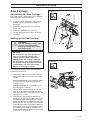
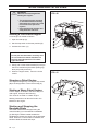
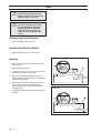
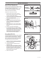
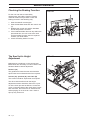
1
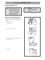
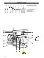
Operator´s manual
SMB 70
SMB 70 E
Please read these instructions carefully and make sure
you understand them before using the one-man sawmill.
English
TABLE OF CONTENTS
Introduction ....................................... 3
Symbols ............................................. 4
Warning Signs ................................... 4
Safety Regulations ............................ 5
Description ........................................ 7
Installation ....................................... 16
Fuel Handling .................................. 23
Starting and Stopping..................... 24
Use .................................................... 26
Maintenance .................................... 30
Technical Data ................................. 36
2 – English
INTRODUCTION
Introduction
This operator’s manual describes in detail how
the one-man sawmill is used and maintained and
how servicing is to be carried out. It also describes the measures to be taken for maximum
safety and how the safety features are designed
and function, as well as how they are inspected,
maintained, and repaired if necessary.
Symbols and warning signs shown on the next
page can be found in this operator’s manual and
on the one-man sawmill. If a decal on the sawmill
has been damaged or is worn, a new warning
decal must be applied as soon as possible in
order to ensure the greatest possible safety
when using the sawmill.
NOTE! The section dealing with safety must
be read and understood by all those who
install, use, or repair the sawmill.
The one-man sawmill shall only be used to cut
boards and planks from logs.
The operator’s manual comprises installation,
usage, and the different maintenance procedures
that can be performed by the operator. More
comprehensive servicing or troubleshooting
should be performed by the dealer’s service
personnel.
The one-man sawmill should be used outdoors
and not in enclosed spaces.
The operator’s manual describes all the requisite
safety features and should be read and understood by the user before the sawmill is assembled.
English –
3
KEY TO SYMBOLS
Symbols
Warning Signs
The symbols below are used in this operator’s
manual.
The decal with the symbols below is found on the
one-man sawmill.
Eye protection and hearing
protection should be used.
Boots or work shoes with
steel toecaps and non-slip
soles should
be worn.
Eye protection should be
used.
Protective gloves should be
worn.
Switch off the engine by
moving the stop switch to the
STOP position before carrying out any checks or maintenance.
Eye protection and hearing
protection should be used.
Protective gloves should be
worn.
Boots or work shoes with steel
toecaps and non-slip soles
should be worn.
Read this manual carefully
and make sure you understand it before attempting to
use the one-man sawmill.
Exercise caution.
Bandsaw blade tension
Bandsaw blade cleaning on
tank
Bandsaw start/stop and
brake
Height setting
Arrow for bandsaw blade
direction
Danger
4 – English
SAFETY REGULATIONS
Safety Regulations
!
WARNING!
A one-man sawmill can be a
dangerous tool that can cause
serious or fatal injury if used
incorrectly or carelessly. It is
very important that the person
using the one-man bandsaw
reads and understands the
content of this manual.
!
WARNING!
Always ensure good ventilation. Exhaust fumes and
sawdust can cause injury or
allergies.
Personal Protective Equipment
The person or persons using the one-man
sawmill or remaining in its close proximity must
be equipped with the personal equipment as set
out below:
1. Hearing protection.
2. Eye protection.
3.
Approved protective gloves.
4. Boots or work shoes with steel toecaps and
non-slip soles.
5. First aid kit.
English –
5
SAFETY REGULATIONS
The One-man Sawmill Safety
Equipment
!
WARNING!
The one-man sawmill must
never be used if any of the
safety devices or guards is
damaged or does not work.
Safety During Use
The safety regulations that apply while using the
one-man sawmill are documented in their respective areas under the section Use on page
26-29.
The operator should observe the following safety
measures before and during use:
There are a number of safety devices and
guards in order to prevent accidents when using
the sawmill. These are described in the sawmill’s
general description. See page 15.
1. Check that all safety devices and guards are
fitted and undamaged.
The safety devices and guards also require
regular inspection and maintenance. Measures
and intervals are documented in the section
Maintenance. See page 30-35.
3. Ensure that there are no people or animals
within the one-man sawmill’s risk zone.
Fuel Safety
5. Adjust the bandsaw guide so that it is as
close to the log as possible. See page 27.
!
WARNING!
The fuel used in the one-man
sawmill has the following
hazardous properties:
1. The fluid, its vapour, and its
exhaust fumes are poisonous.
2. Can cause skin irritation.
3. Is highly inflammable.
Special safety regulations apply to the fuel used
with the one-man sawmill. These are documented
in the section Fuel Handling on page 23.
Personnel
The following apply to personnel using the oneman sawmill:
1. Shall have read and understood the content
of this operator’s manual.
2. Must not be under the influence of alcohol or
medication, nor suffering from tiredness.
3. Good lighting is required when using the
sawmill outside daylight hours.
4. Shall not be a minor.
5. Earthed circuit breaker recommended.
Risk Zone
The risk zone is evident from the picture to the
right.
No unauthorised persons may be present in the
risk zone.
The risk zone should also be kept free of foreign
objects and the ground within the risk zone
should be flat so that the operator avoids stumbling.
6 – English
2. Check that no fuel has been spilt on the
outside of the tank or on the ground.
4. The stopping and locking devices required to
fasten the log shall be used in the intended
manner. See pages 26-28.
6. Adjust the scale and check that the bandsaw
moves freely over the short and long log
supports by the red markings on the scale.
See page 22.
FIG. 1
DESCRIPTION
One-man Sawmill Petrol Engine
The one-man sawmill consists of two main parts:
• The carriage with engine and saw
• Rails
The carriage consists of the following:
1. Scale
2. Scale pointer
3. Bandsaw blade cleaning fluid tank
4. Start/stop control
5. Handlebars
6. Rails
7. Adjustable band guide lock
8. Adjustable band guide
9. Bandsaw blade
10. Rail guard
11. Support wheels
12. Runners
13. Lifting handle
14.
15.
16.
17.
18.
19.
20.
21.
22.
23.
24.
25.
26.
27.
28.
29.
30.
Stop switch
Petrol engine
Exhaust system with muffler
Fuel tank
Chain guard
Height setting screw
Upper bandsaw blade guard
Band wheel guard
Safety switch
Bandsaw blade guard
Scraper
Frame
Band wheel
Band tension crank
Band wheel adjuster
Height setting crank
Index plate
English –
7
DESCRIPTION
Tools and operator’s manual
38. Open ended spanner 13-15 mm
39. Open ended spanner 17-19 mm
40. Socket spanner
41. Combination spanner 13-19
42. Combination spanner
43. Allen key 4 mm
44. Allen key 5 mm
45. This operator’s manual
8 – English
DESCRIPTION
One-man Sawmill Electric Motor
The one-man sawmill consists of two main parts:
• The carriage with motor and saw
• Rails
The carriage consists of the following:
1. Scale
2. Scale pointer
3. Bandsaw blade cleaning fluid tank
4. Start/stop control
5. Handlebars
6. Rails
7. Adjustable band guide lock
8. Adjustable band guide
9. Bandsaw blade
10. Rail guard
11. Support wheels
12. Runners
13. Lifting handle
18.
19.
20.
21.
22.
23.
24.
25.
26.
27.
28.
29.
30.
31.
32.
33.
34.
35.
36.
37.
Chain guard
Height setting screw
Upper bandsaw blade guard
Band wheel guard
Safety switch
Bandsaw blade guard
Scraper
Frame
Band wheel
Band tension crank
Band wheel adjuster
Height setting crank
Index plate
Connector with polarity reversal
Stop switch
Start switch
Safety switch connector
Main switch
Distribution box
Electric motor
English –
9
DESCRIPTION
Tools and operator’s manual
38. Open ended spanner 13-15 mm
39. Open ended spanner 17-19 mm
40. Socket spanner
41. Combination spanner 13-19
42. Combination spanner
43. Allen key 4 mm
44. Allen key 5 mm
45. This operator’s manual
10 – English
DESCRIPTION
Carriage (FIG 2)
FIG. 2
The carriage consists of the following parts:
•
•
•
•
Steel structure with runner wheels against
the rails and guides for the saw’s up and
down movement.
Two screws for the saw’s vertical adjustment.
The screws are connected to a chain and are
operated by a crank, equipped with an index
plate.
Handle with operating mechanism
Saw unit with the following parts:
• Engine.
• Adjustable band wheels.
• Bandsaw blade.
• Adjustable support for optimal bandsaw
blade guiding.
• Fuel tank (petrol engine) for petrol. See
the Fuel Handling section.
• Cleaning fluid tank for the bandsaw blade.
• Muffler (petrol engine).
FIG. 3
Frame (FIG. 3) and (FIG. 4)
The carriage frame consists of welded square
tubing with requisite corner reinforcement for
stability during cutting.
The frame is equipped with two round runners for
the saw unit's up and down movement. The
guides transfer the saw carriage’s lateral forces
to the frame.
On the underside of the frame are four runners,
fitted with bearings, with slots for securing and
smooth running along the rails.
The carriage is equipped with two adjustable
bearings, which run against the underside of the
rails, to prevent it from lifting.
FIG. 4
Height Setting (FIG. 4)
The saw unit is secured vertically by two interacting screws. The screws are connected to a chain
for precise and simultaneous movement.
A crank (29) is fitted on the top section of one of
the screws, and is used to set the exact dimension of the timber thickness. One turn of the
crank moves the bandsaw blade 5 mm. The
height of the bandsaw blade above the rails’
cross members is read on the scale (1).
There are two red markings on the scale that
indicate the lowest saw height with the timber
support raised, one red line for the long timber
support and one red line for the short one.
CAUTION! Sawing under the respective markings will damage the bandsaw.
English –
11
DESCRIPTION
Handlebars (FIG. 5)
The saw carriage is operated and moved forward with a vibration-free steering handlebar (5),
located on the carriage’s right hand side. The
handlebar is equipped with start and stop
controls (4) for the bandsaw.
FIG 5
Cleaning Tank (FIG. 5)
The saw carriage is equipped with a cleaning
tank (3). The tank is located beside the handlebars. Cleaning fluid is applied to the blade by
opening the tank valve.
Band Wheels (FIG 6)
The bandsaw blade runs over two band wheels
(26), which are made of cast aluminium and are
balanced to provide smooth operation. The band
wheels are equipped with bearings, and are
adjustable, partly to tension the bandsaw blade
and partly to adjust the correct alignment of the
bandsaw blade.
The band wheels are fitted with scrapers so that
sawdust and the like does not penetrate between
the bandsaw blade and the band wheel.
One of the band wheels is powered by the
engine/motor via an adjustable belt.
FIG 6
Bandsaw and Band Guide (FIG 6)
Two band guides (8) are used to keep the
bandsaw blade (9) in the correct position during
cutting. One of the band guides is placed in front
of the powered band wheel and ensures correct
entry onto the wheel. The other band guide is
adjustable and is positioned above the bandsaw
blade before it runs onto the log. This band guide
absorbs the forces from the log and prevents the
bandsaw blade from shifting.
FIG 7
Propulsion
Petrol Engine (FIG. 7)
The one-man saw is run with an air-cooled fourstroke engine (15). A clutch is located on the
engine’s drive axle that starts, stops, and brakes
the bandsaw blade. The speed of the engine is
regulated with the operating control on the
handlebars. See the enclosed manual for a
description of the engine.
Electric Motor (FIG. 8)
The one-man saw is powered by a 3-phase motor
(37). The motor is started and stopped with the
start and stop buttons on the distribution box,
which has built-in motor protection. There is also
a connection for an electric cable with single
polarity reversal (FIG. 8A), and a main switch
(FIG. 8B.). A clutch is located on the motor’s axle
and starts, stops, and brakes the bandsaw blade.
12 – English
FIG 8
DESCRIPTION
Rails
The rails consist of two sections (standard
delivery). Each section is 3 m. The sections are
aligned and bolted together into a track for the
carriage. The rail sections are bolted together
and fastened using M12 bolts with nuts, which
assures stability and ensures that the carriage
runs straight.
The rails also have a number of transverse log
bolsters, designed to provide a stable support for
the log to be cut or the planks to be trimmed.
The rails’ transverse log bolsters are equipped
with:
• Folding stop for the log
• Log lock
• Height adjustment of one end of the log
The rails are also fitted with stops at both ends
for the saw carriage, as well as adjustable
jointing plates on the section joints.
FIG. 9
FIG. 10
Log Bolsters (A)
Folding Stops (C)
The rails have a number of transverse log bolsters that provide a stable support for the log to
be cut or the planks to be trimmed.
There are a number of folding stops for the log on
the left-hand side of the rails. To increase usability, the stops come in two different lengths.
Height Adjustment (B)
Log Locks (D)
The height adjustment is designed to raise the
small end of the log, so that the core becomes
horizontal.
The log locks consist of a cam with handle,
housed in a moveable unit. The locks are used to
secure the log against the folding stops.
English –
13
DESCRIPTION
Rail Stop
Rail stops are fitted at the ends of the rails (A).
The stop is mounted using a bolt from the side of
the rail.
Adjustable Support Feet
Adjustable support feet are mounted by each log
bolster. You can fine tune the rails’ adjustment
using the support feet.
Rail Guard
The saw carriage is equipped with four rail
guards that run above the rails. The rail guards
have the tasks of keeping the rails clean and
preventing crush injuries between the runner
wheels and rails.
14 – English
FIG. 11
FIG. 12
FIG. 13
DESCRIPTION
Safety Devices
FIG 14
The one-man saw is fitted with a number of
safety devices, which are described under the
headings below.
!
WARNING!
The one-man saw must not be
started if any of the safety
devices have been removed,
are defective, or are not
working.
Band Wheel Guard (21)
The band wheels are protected from contact by a
cover on each side. Each cover is equipped with
a safety key that cuts the mains power to the
start switch for units with an electric motor and
short-circuits the petrol engine when the covers
are removed. There are 3 rubber straps on the
guard to allow easy dismantling and assembly
when changing the bandsaw blade. The safety
key activates a safety switch when the covers are
fitted. The rail stop (FIG. 14A) prevents the
bandsaw carriage from rolling off the rails.
FIG 15
Bandsaw Blade Guard (upper)
(20)
The upper section of the bandsaw blade runs in
a slot.
Bandsaw Blade Guard (lower)
(23)
The part of the bandsaw blade that is not in the
log when cutting should be covered by the
adjustable guard.
FIG 16
Bandsaw Blade Brake (FIG. 16)
The bandsaw is equipped with an integrated
brake/clutch (A) that stops the band wheel in
order to quickly stop the band wheel when the
handlebar controls (4) are released.
Starter, Electric Motor (FIG. 17)
The electrically powered saw is equipped with a
main switch (35), safety switch connector with
phase inverter (31), contact for safety switch (A),
and start switch (33). The motor is started with
the green start switch and stopped with the red
stop switch (32). The electric motor stops when
not in use for longer periods or when sawing is
completed. The starter is equipped with a 0-volt
trigger. This means that the sawmill’s electric
motor must be restarted after a power outage.
FIG 17
Stop Switch, Petrol Engine (14)
On the petrol engine, the stop switch is located
on the engine body and with electric start the
engine is stopped with the key.
English –
15
INSTALLATION
Unpacking
Unpack the one-man sawmill and check that the
delivery is complete. Check that no parts are
damaged. If any part is damaged, report this to
the carriers.
The operator’s manual includes detailed instructions about safety, assembly, use, and maintenance of the one-man sawmill.
Installation
Installation Site
The one-man sawmill with petrol engine should
be installed outdoors.
There should be space to lay out timber and
sawn wood.
Rails
Place the rail sections after each other on the
transverse wooden beams, which are placed
under each log bolster, and an extra transverse
wooden beam by the joints between the sections.
Parts that are included are pictured in the Description section on page 7-10 . Component parts
are packed according to the following:
1.
2.
3.
4.
5.
6.
Rail sections (quantity according to the order).
Split saw carriage with engine/motor.
4 rail guards.
Bandsaw blade.
Tanks with hoses.
Assembly components.
Continue as follows:
1. Assemble the adjustable feet under each of
the 16 log bolsters. Adjust, by using the
adjustable feet and the rails’ bedding, until
the rail sections form a straight line and the
rails sit firmly on each wooden beam. See
FIG. 18.
2. Loosely bolt together the rail sections using
the supplied jointing plates and M12 nuts and
bolts. See FIG. 20.
3. Finely adjust the rails and tighten all the
bolts. Tighten the bolted joints to 5-10 Nm.
See FIG. 18.
4. Fit the stops to the ends of the rails (see page
14, FIG. 11), as well as the folding stops, log
lift, and log lock (see page 13, FIG 10).
5. Load the rails above each wooden beam and
check that the rails do not move.
FIG. 18
Aligning the rails
FIG. 19
Adjustable foot
16 –English
FIG. 20
Bolted joint
INSTALLATION
Saw Carriage
FIG. 21
Assembling the Saw Carriage
The wheel fixture is assembled in the packaging,
where the sides are disassembled.
1. Crank the height adjustment crank (29) so
that the runner (12) reaches outside the
packaging.
2. Attach the wheel fixture (FIG 21B) to the
runner (12).
3. Attach the stabilising stay (FIG 21A)
4. Loosely attach the frame (25) to its fixture
and guide.
Setting up the Saw Carriage
!
WARNING!
The saw carriage is heavy. Two
persons are required when
setting up. Always wear boots
with steel toecaps.
CAUTION!
Do not drop the saw carriage onto the
rails or any other hard surface too
heavily. This will result in permanent
damage to the saw carriage’s bearings.
Do not place the saw carriage directly on
the ground so that dirt and unnecessary
contamination can come into contact
with the saw carriage’s wheels.
FIG. 22
Place the saw carriage on the rails and make
adjustments as follows:
1. Two persons take hold of the saw carriage,
one on each side. Hold the saw carriage as
follows:
The right-hand side: by the bandsaw blade
tension crank and under the band wheel’s
protective cover.
The left-hand side: by the handle (13) on
the motor/engine console.
2. Lift and place the saw carriage so that the
grooves in its wheels are positioned above
their respective rails. Carefully lower the saw
carriage onto the rails.
3. The one-man sawmill can be fitted with a
wheel kit (FIG. 22) and a handle (Part no. 531
01 95-93) to make handling the saw carriage
easier. The wheel kit is inserted into the steel
structure by the saw carriage’s runner wheels
on the left-hand side. The handle is attached
to the wheel housing on the right-hand side of
the sawmill. When using the wheel kit and
handle, the sawmill can be moved and placed
on the rails by one person.
English –
17
INSTALLATION
Saw Carriage Adjustment
FIG. 23
The saw carriage is aligned on the rails by fitting
its lower guide wheels and rail guards. The lower
guide bearings have the task of preventing the
saw carriage from tilting and the rail guards keep
the rails and the saw carriage’s wheels free from
dirt and the like. Assembled on the saw carriage
are:
•
Two lower guide wheels
•
Four rail guards.
Assembly is done as follows:
1. Fix the guide wheel’s bracket in place with a
screw. Place a 0.2 mm feeler gauge between
the bearing and rail.
FIG. 24
0,2 mm
2. Press the bearing against the rail and tighten
the bearing bracket screw. Tightening torque:
40-50 Nm. Now remove the feeler gauge.
3. Carry out 1-2 above for the remaining guide
wheels.
4. Position the four rail guards above the wheel.
5. Adjust and screw into place the frame (25)
and guide FIG. 26 A.
FIG. 25
FIG. 26
18 –English
INSTALLATION
Handlebars (FIG. 27)
Attach the handlebars with the start lever (5) at a
suitable height on the right-hand frame (25) and
tighten the screws to 10 Nm. Attach the weight
(A) to the rear end of the handlebars.
Band Cleaning Tank (FIG. 28)
The tank (3) is placed on the mounting located
on the right-hand side of the sawmill. The band
cleaning fluid flow is regulated with a continuously variable manual valve on the tank (FIG.
28A).
FIG. 27
FIG. 28
The tank (3) can be easily removed from the
sawmill. The spiral hose is inserted through the
hole in the band guide (8) and is connected in
the hole on the plate mounted on the adjustable
band guide. The fluid can then run down and
clean the bandsaw blade.
English –
19
INSTALLATION
Propulsion
1. Place the engine/motor on the engine/motor
console and attach the drive belt.
2. Bolt the engine/motor (petrol or electric) onto
the engine/motor console.
3. Connect the cable to the clutch control arm
(A).
4. Attach the mounting for the drive disc (B), so
that the clutch does not rotate.
5. Tighten the belt with the belt tension device
(FIG. 31 A). A correctly adjusted belt can be
moved 0.5 cm with one finger (FIG. 31 B). If
necessary, adjust the engine/motor console
mounted in the lengthways slot to attain the
correct belt tension.
6. Connect the cable to the start lever (FIG. 30
E), check that the clutch is activated. When
the start lever (FIG 30 F) is activated, the
spring in the control arm on the clutch shall
be lightly compressed.
FIG 29
FIG 30
Wire adjustment
The wire that engages the clutch must be adjusted so that there is no pressure on the clutch
arm that is connected to the clutch. The easiest
way to do this is to adjust the wire so that it is
completely slack when the clutch is not engaged.
Adjustment is by means of the adjuster nipples
on the starter yoke and the engine bracket (FIG
30 G and FIG X A).
It is also important that the attachment to the
clutch is able to swing (FIG X B). The spring in
the fastener prevents excessive leverage being
applied to the clutch arm.
On saw mills with four-stroke engines, the wire
connected to the engine is adjusted using nipple
(FIG X), so that the throttle lever is activated by
the swinging motion (FIG X B) of the wire fastener near the clutch and therefore increases the
engine speed before the clutch is engaged.
FIG X
FIG 31
Petrol Engine
Connect the cable from the covers’ safety switch
(22) to the contact (FIG. 29 D) on the engine.
Electric Motor
Connect the cable from the covers’ safety switch
to the contact on the distribution box (FIG. 32 A).
The contact for the electrical cable for the electric
motor has polarity reversal (31). Make sure that
the main switch (34) is set to 0.
!
20 –English
WARNING!
Check that the main switch is
set to 0, and be sure to invert
the phase if the sawmill runs in
the wrong direction.
FIG 32
INSTALLATION
Bandsaw Blade
!
FIG. 33
WARNING!
Wear protective gloves whenever
you handle the bandsaw blade!
On delivery a new bandsaw blade
is rolled up and is in a state of
high mechanical tension. Carefully unpack the bandsaw blade
so that it does not fly out and
cause physical injury!
Only bandsaw blades with the part number
531 0194-65 may be used.
FIG. 34
Fit the bandsaw blade as follows:
1. Remove the guards over the band wheels.
The guards are attached by three rubber
straps, one upper, one lower, and one in the
middle.
2. Crank the band tension crank (27) anticlockwise so that the distance between the band
wheels is as small as possible.
3. Loosen the crank (FIG. 33A), drop the band
guard (23), and attach the bandsaw blade
with the teeth facing. Make sure that the
bandsaw blade enters the adjustable band
guide (8) and the fixed band support (FIG.
33B).
FIG. 35
4. Release the belt tensioner by loosening the
belt idler from the engine/motor. See FIG. 34.
5. Tension the bandsaw blade using the crank
(27) until the spring washers are correctly
compressed. See FIG. 36A. Turn the
bandsaw wheels a few turns by hand, so that
the bandsaw blade centres on the band
wheels. CAUTION! It is important that the
bandsaw blade is not tensioned too much so
that the washers are completely compressed.
See FIG. 36B. The washers should have a
degree of springiness to take up variations in
band tension. Incorrect band tension (too
hard or too loose) means that the bandsaw
blade runs a risk of roaming and coming
loose from the band wheel.
FIG. 36
6. Tension the belt FIG. 35 by pulling the handle so that the idler tightens the drive belt.
Lock it. A correctly adjusted belt can be
moved 0.5 cm with one finger.
7. Adjust the band guide’s blocks by loosening
the bolts 1 and 2 (FIG. 33). Adjust the blocks
from both directions so that they lie lightly
against the band.
8. Fold up the band guard (23).
9. Position the guards over the band wheels
and secure them with the rubber straps.
Ensure that the safety keys are in the tracks.
English –
21
INSTALLATION
Scale (FIG 37)
Fit the ruler on the bandsaw blade’s upper guard
as follows:
FIG. 37
1. Insert the ruler through the top of the scale
pointer FIG. 37 A. The greatest value on the
ruler shall face downwards.
2. Measure the distance between the underside
of the bandsaw blade and the log bolster’s
upper section FIG. 38 B. NOTE! During this
procedure the bandsaw blade should be
tensioned and adjusted.
3. Set the scale so that the scale pointer has
the same value and can be read on the scale
FIG. 37 C.
4. Bolt the scale to the wheel housing FIG. 37 D.
5. Check that the bandsaw blade moves freely
over the long and short log supports when
the red mark can be read on the scale
pointer. FIG. 37 E
FIG. 38
22 –English
FUEL HANDLING
Fuel
FIG. 39
Fuel Safety
!
WARNING!
The fuel used in the one-man
sawmill has the following
hazardous properties:
1. The fluid, its vapour, and its
exhaust fumes are poisonous.
2. Can cause skin irritation.
3. Is highly inflammable.
The following are absolutely forbidden when
fuelling:
•
Smoking.
•
To have flames or hot objects in close
proximity.
•
To have the engine running.
Petrol
Use leaded or unleaded petrol. The lowest
recommended octane grade is 90. If you run the
engine on a lower octane grade than 90, socalled knocking can occur. This leads to an
increased engine temperature, which can result
in serious engine damage.
Fuelling
1. Clean around the fuel cap.
2. Open the fuel cap slowly so that any excess
pressure is released.
3. Tighten the fuel cap carefully after fuelling.
Clean the fuel tank regularly. The fuel filter should
be changed at least once a year. Contamination
in the fuel tanks causes malfunction.
English –
23
STARTING AND STOPPING
!
WARNING!
Observe the following before
starting the engine:
FIG. 40
• The engine must be mounted
in the sawmill before starting.
Otherwise the clutch can come
loose and cause personal
injuries.
• Keep people and animals well
away from the risk zone.
Starting a Cold Petrol Engine
A cold engine is started as follows:
1. Open the fuel tap (A).
2. Set the stop switch to the start position (B).
3. Activate the choke. (C)
CAUTION!
Do not pull out the starter cord fully and
do not release the starter handle from
the fully extended position. This damages the starter.
4. Slowly pull out the starter handle (D) until you
feel some resistance (the starter pawls grip).
Now pull quickly and firmly.
5. When the engine starts, return the choke
control.
Stopping a Petrol Engine
The engine is stopped by moving the stop switch
(B) to the stop position. Close the fuel tap (A).
Starting a Warm Petrol Engine
A warm engine is started in the same way as a
cold engine, except for the following:
The choke is not used on a warm engine.
Starting instructions can also be found in the
Manual for the engine.
Starting and Stopping the
Bandsaw Blade
The blade is started and stopped using the
control handle (4) on the sawmill’s handlebars
(5). Moving the starter handle towards the
handlebars activates the clutch and the bandsaw
starts. When the control handle is released, the
bandsaw blade is braked and stops.
24 – English
FIG. 41
STARTING AND STOPPING
Starting the Electric Sawmill
!
WARNING!
The sawmill must not be
started until the appropriate
current and voltage has been
connected. Use suitable personnel trained in the country in
question.
FIG. 42
CAUTION!
The first time the sawmill is started or
when it has been moved to another
power outlet:
•
•
Test start the sawmill in accordance
with the starting instructions.
Check the direction of the bandsaw
blade. If the bandsaw blade runs in
the wrong direction, there is a phase
inverter on the power connector
(FIG. 42). The phase is inverted with
the aid of a screwdriver, as illustrated in FIG. 42.
FIG. 43
Starting the Electric Motor
1. Check that the power cable is connected
correctly.
2. Set the main switch (35) to 1.
3. Start the motor with the green start button
(33). The motor starts.
Stopping the Electric Motor
1. The electric motor is stopped with the raised
red button (32).
2. Set the main switch (35) to 0.
Starting and Stopping the
Bandsaw Blade
FIG. 44
The blade is started and stopped using the
control handle (4) on the sawmill’s handlebars
(5). Moving the starter handle towards the
handlebars activates the clutch and the bandsaw
starts. When the control handle is released, the
bandsaw blade is braked and stops.
English –
25
USE
Securing the Log
!
WARNING!
Exercise care during all log
handling. Heavy lift! Wear boots
or shoes fitted with steel toecaps.
1. Fold up the stops (C) on the left-hand side of
the rails.
2. Roll the log up against the stops (C). The log
must not come closer:
• than 300 mm to the end of the rails
• than 500 mm to the start of the rails
This means that when using two rail sections,
the maximum log length is 5200 mm.
3. Raise the log using the height adjuster (B) so
that the log’s core is horizontal.
4. Lock the log in position with the log lock (D).
FIG. 46
26 – English
FIG. 45
USE
Calculating the Yield
Measure the log’s top end and determine how
the log should be utilised for the timber in question. Include the thickness of the saw cut in the
calculation.
FIG. 47
The saw cut thickness = 2 mm.
Sawing
!
WARNING!
Use the following protective
equipment when sawing:
FIG. 48
• Boots or shoes fitted with steel toecaps.
• Hearing protection.
• Eye protection.
• Always have a first aid kit nearby.
Before starting the engine, check that:
• All guards are fitted and undamaged.
• No unauthorised personnel are within
the risk zone.
1. Place the log on the rails facing the folding
log supports (FIG. 46).
2. Set the height of the bandsaw blade using
the crank (29).
3. Clean any sand from the log, if necessary.
This results in less wear.
4. Place the band guide (8) as close as possible
to the log without the log and band guide
touching each other. Lock the band guide
using the lever (7).
5. Check the cleaning fluid tank (3) and fill with
cleaning fluid if necessary. Use a cleaning
fluid with lubricating properties, for example,
water and detergent. The mixture should be
made up of 80% water and 20% detergent.
Wintertime: add windscreen washer fluid.
6. Check the fuel tank (17) and fill with fuel if
necessary. See page 23.
English –
27
USE
!
!
WARNING!
Check during sawing that the
bandsaw blade does not hit the
folding stops or log lock.
WARNING!
The saw carriage must not be
moved backwards while the
bandsaw blade is in motion.
Otherwise the bandsaw can
jump off and cause personal
injury.
Starting the Petrol Engine
1. Start the engine. See page 24.
Starting the Electric Motor
1. Start the electric motor. See page 25.
Sawing
FIG. 49
2. Move the saw carriage forwards and cut off
the sapwood.
3. Remove the sapwood.
4. Loosen the log, turn it 180°, lower the height
adjuster (B), and secure the log.
5. Set the required cutting height using the
height adjustment crank (B). This determines
the width of the board.
6. Set the band guide as close as possible to
the log without the log and band guide
touching each other. Lock the band guide
using its lever.
7. Cut off the sapwood on the other side. See p
2 and 3.
28 – English
FIG. 50
USE
8. Loosen the log and turn it 90°.
FIG. 51
9. Adjust the top end of the log using the height
adjuster and secure the log with the flat
surface tightened against the stop.
10. Cut off the upper sapwood.
11. Loosen the log, turn it 180°, lower the height
adjuster, and secure the log.
FIG. 52
12. Cut the block according to the previous
instructions. Remember to compensate for
the thickness of the bandsaw blade for each
adjustment of the bandsaw blade’s height.
Data for the height adjustment crank:
• 1 turn = 5 mm.
The scale can also be used for varying standard
dimensions.
Edging
Several boards can be edged simultaneously by
clamping them against the stop.
FIG. 53
Place a batten between the boards and the stop
in order to keep the boards still during cutting.
The batten should be at least 50 x 100 mm.
English –
29
MAINTENANCE
Bandsaw Blade
!
WARNING!
The bandsaw blade is sharp and
can cause cuts. Warning for
personal injury. Wear protective
gloves whenever you handle the
bandsaw blade.
The bandsaw blade should be set and sharpened
regularly to give optimal performance. During
normal sawing of most species of wood this
should be done at intervals of approx. 2 hours of
effective cutting time. Effective cutting time
refers to only the time that the bandsaw blade
actually works. The bandsaw blade should be
sharpened more frequently when cutting those
species of wood with a high sand content. For
blade sharpening, see the separate instructions
for the Grindlux bandsaw blade grinder.
Dismantling
Dismantle the bandsaw blade as follows:
1. Remove the guards over the band wheels.
See page 21.
2. Loosen the right-hand band wheel by
cranking about 10 turns counter-clockwise.
3. Carefully remove the bandsaw blade.
Cleaning and inspection
Clean sawdust and any coating from the bandsaw
blade. Now check whether there are any cracks
(A) in the gullets. Small cracks can be ground
away when sharpening the bandsaw blade. If the
cracks are so large that they cannot be ground
away, the bandsaw blade should be discarded.
Cracks in the gullets are the most common cause
of bandsaw blade breakage. The bandsaw blade
can be ground to a minimum width of 24 mm. See
FIG. 54. A new bandsaw blade is 32 mm wide.
The bandsaw blade should be discarded once
any part of it reaches the minimum width.
!
WARNING!
Never use a damaged bandsaw
blade.
Setting the Saw
The bandsaw blade’s teeth should be set to the
dimensions shown in the adjoining figure. Every
third tooth should remain unset. The teeth
should be set as follows:
B=Set to the right, 0.4-0.5 mm.
C=Set to the left, 0.4-0.5 mm
D=Not set.
The more accurate the set is made, the straighter
and smoother the bandsaw blade runs when
cutting the log. The bandsaw blade should be set,
at a minimum, after every third sharpening.
30 – English
FIG. 54
min. 24 mm
FIG. 55
MAINTENANCE
Saw Setting Pliers
FIG. 56
For optimal results the bandsaw blade should be
set using the saw setting pliers as described on
page 30.
The saw setting pliers are adjusted to the correct
setting size.
Place the saw setting pliers over the saw tooth
so that the pliers’ fixing angles rest on the two
closest teeth.
Activate the pliers and the saw tooth will be set
away from the operator.
English –
31
MAINTENANCE
Sharpening
!
FIG. 57
WARNING!
The bandsaw blade is sharp
and can cause cuts. Warning
for personal injury. Wear
protective gloves whenever
you handle the bandsaw blade.
After sharpening, the bandsaw blade should be
set as described in the instructions on the
previous page.
FIG. 58
The more accurate the sharpening, the straighter
and smoother the bandsaw blade runs when
cutting the log.
Radii
The radius in the area (A) should be 1-3 mm.
A radius under 1 mm increases the risk of
cracking.
A radius over 3 mm means that the chips are not
broken.
FIG. 59
Angles
The clearance angle should be 10-12° and the
cutting angle (F) varies depending on the species of wood as follows:
Hardwoods or frozen timber
Medium hardwoods
Softwoods
7°
10°
14°
Before sharpening, the bandsaw blade’s teeth
should be set using the saw setting pliers.
The rake angle should be 90°. See the figure to
the right.
Shape of the Tooth
As the bandsaw blade is sharpened it is
important that the teeth and tooth valleys keep
their original shape.
For optimal results, the bandsaw blade should
be sharpened with the grinder. The procedure is
described on the following pages.
On delivery, the grinder is adjusted for the
correct angles and tooth shape.
32 – English
FIG. 60
MAINTENANCE
Band Wheel Adjustment
After the one-man saw has been used for a long
period, the band wheel bearings will start to wear
and change position. Meanwhile, the
foundation’s working geometry will have stabilised. This means the parallelism of the band
wheels may need to be adjusted.
FIG. 61
Adjustment is performed as follows:
1. Ensure that the electric power has been
disconnected. Unplug the electrical contact
or short-circuit the petrol engine.
2. Loosen the belt tension by releasing the idler
to the V-belt, so that the band wheel is free
and can be rotated by hand.
3. The bandsaw blade should be fitted and
adjusted.
4. Adjust the right-hand band wheel using the
screw (F). The screw is locked with a lock
nut, which should be loosened during
adjustment.
5. Check the alignment of the bandsaw blade
after adjustment by rotating the band wheel
by hand.
6. See FIG. 61 for the correct position.
7. If the bandsaw blade is not aligned, adjust
the right band wheel with the spacer located
on the outside of the band wheel. The wheel
is dismantled and the spacer is placed on the
innermost part of the wheel axle and the
wheel is then re-mounted. Repeat steps 2 to
5 until the bandsaw blade is aligned.
Drive Belt (FIG. 63)
The drive belt wears as the saw is used. The belt
should be replaced after 200 hours of operation
to avoid belt failure during operation. If the drive
slips or the belts need to be frequently adjusted,
this is a sign that the belts need to be replaced.
To replace the belt, proceed as follows:
FIG. 62
FIG. 63
1. Unplug the electrical contact from the distribution box or short-circuit the petrol engine.
2. Loosen the belt guard.
3. Loosen the idler (A) completely with the
locking lever (B).
4. Change the belt and then tighten the belt by
pulling the handle (C) and tightening the idler
(A) and locking the idler with the locking lever
(B). When the belt is correctly tensioned, it
should be possible to move it about 0.5 cm in
each direction using one finger.
5. Attach the belt guard.
English –
33
MAINTENANCE
Checking the Braking Function
FIG. 64
For the one-man saw to meet safety
requirements, the braking function must be
checked at least once per week. Check the
braking function in the following way:
1. Start the sawmill motor/engine.
2. Start the bandsaw blade with the control unit
(4).
3. Release the control unit and the bandsaw
should stop within 5 seconds.
4. If the bandsaw blade does not stop within the
prescribed time, the unit is not to be used
until the braking function clutch is repaired.
Contact your local dealer.
5. Check the Safety Switch Function.
The Saw Unit’s Height
Adjustment
Maintenance procedures on the components
listed below are necessary in order to assure the
bandsaw blade’s vertical adjustment.
Runners (12)
The guides that locate the saw unit should be
wiped clean and moistened with oil as required.
Screws (19), sprocket (A), and chain (B)
The screws should be wiped clean as required.
The drive chain that links both the height
adjustment screws should be oiled once a year.
To oil the chain proceed as follows: Loosen the
cover on the short side of the chain guard. Crank
back and forth, about 20 turns in each direction,
while spraying oil on the chain. Use a cloth to
wipe up any excess oil.
34 – English
FIG. 65
MAINTENANCE
Maintenance
The maintenance described in this section refers
to measures that can be carried out by the user.
If faults are detected that cannot be rectified in
accordance with this operator’s manual, contact
your nearest authorised service representative.
Daily Maintenance
1. Check that nuts and screws are tight.
2. Height adjustment mechanism:
Clean both the screws and the guides. See
page 34.
3. Adjust the bandsaw blade tension. See page
21.
4. Check that the bandsaw blade’s cleaning
system works. If the cleaning fluid is depleted
on an ongoing basis, then the cleaning
system works.
5. Clean any sawdust from the bandsaw blade
guides.
6. Check that all safety devices are undamaged
and work. Check:
• Start/stop devices
• Electrical contacts
• Band wheel guards
• Safety switch for the band guards
• Rail stop
• Rail guards
• Belt guard
• Electrical cables and electrical connections
7. Set and sharpen the bandsaw blade as
required. When cutting timber with a normal
sand content and hardness, these actions
should be carried out after about 1 hour of
sawing (time for adjustments, timber handling, etc are not included). See pages 30-32.
Weekly Maintenance
1. Petrol Engine Maintenance (see the engine
manual).
2. Clean the bandsaw blade scrapers.
3. Clean the height adjustment screws, guides,
and chain. See page 34.
4. Check the belt tension and adjust if required.
See page 33.
5. Clean around the rails. Remove sawdust,
bark, and wood chips to facilitate handling of
the one-man saw.
Monthly Maintenance
1. Checking the Clutch Function. See page 34.
2. Clean the inside of the bandsaw’s cleaning
fluid tank.
3. Check cables and connections.
4. Check that the saw carriage runs easily and
that no binding is felt which can indicate
bearing damage. Replace the wheels if
needed. See page 18.
5. Adjust the play on the bearings that run
against the underside of the rails. See page
18.
6. Check the bolted joints on the rail sections.
See page 16.
7. Check that the rails rest against all contact
points on the wooden beams.
Storage
If the one-man sawmill needs to be stored for a
long period without being used the following
applies:
1. Empty and clean the fuel tank.
2. Empty and clean the bandsaw’s cleaning
fluid tank.
3. Remove the bandsaw blade.
4. Spray preservative oil in the spark plug hole
and carburettor while turning the engine over
with the starter handle.
5. Remove the saw carriage and unbolt the rail
sections.
6. Oil all parts.
7. Store the one-man saw in a dry location.
8. After a period of one year the following
measures apply:
• Spray preservative oil in the spark plug
hole and carburettor while turning the engine
over with the starter handle.
• Oil all parts.
English –
35
TECHNICAL DATA
Petrol Engine
Cylinder displacement, cm3:
Idle speed, rpm:
Max. speed during running in, rpm:
Power, kW/rpm:
Max. torque:
389
1 400 + 150
2 800
9.6 / 3 600
2.7 kg-m / 2 500 revs
Fuel:
Volume, fuel tank:
Fuel consumption:
Cooling system
Ignition system:
Axle rotation:
Petrol, 95-98 octane
6.5 litres
230 g/Hpg
Fan cooled
Transistor
Anti-clockwise
Electric Motor
Power 380-420 delta connection:
Ampere:
Power 220-240 delta connection:
Ampere:
Power 220 delta connection:
Ampere:
50 Hz 5.5 kW, 2855 rpm
10.50
50 Hz 5.5 kW, 2855 rpm
18.20
50 Hz 5.5 kW, 2855 rpm
19.90
Bandsaw Blade Cleaning
Volume, cleaning fluid tank, litres:
Cleaning fluid:
16 litres
Detergent and water. In winter, mixed
with windscreen washer fluid
Weights
The saw carriage, petrol engine, kg:
The saw carriage, electric motor, kg:
Two rail sections, kg:
182
184
115
Bandsaw Blade
Bandsaw blade speed, petrol engine, m/s:
Bandsaw blade speed, electric motor, m/s:
Pitch, mm:
Width, mm:
Thickness, mm:
Length, mm:
Part number:
35
35
25
35
1 + set
3 570
531 01 94-85
Sawing
Max. log height, mm:
Max. log width, mm:
Rec. speed when sawing with petrol engine,
rpm:
The log length is determined by the number
of available rail sections.
Height adjustment crank/turns, mm:
Index plate, resolution, mm:
36 – English
700
500
2 800 / 2 900
5
1
TECHNICAL DATA
Noise Levels
Equivalent (see note 1) noise intensity at
operator’s ear during sawing, measured according to relevant international
standards, dB(A)
Petrol engine:
Electric motor:
97.2
95.6
Equivalent (see note 1) noise level
measured according to relevant international standards, dB(A)
Petrol engine:
Electric motor:
112.8
107.4
Vibration Levels
(See note 2)
Vibration level in the handle, during
sawing, according to international
standards, m/s2
Petrol engine:
Electric motor:
2.2
0.7
Note 1: Equivalent noise level is, according to ISO 7182 and ISO 9207, calculated as the time-weighted
energy total for noise levels under various working conditions with the following time distribution: 1/2
idling, 1/2 full load.
Note 2: Equivalent vibration level is, according to ISO 7505, calculated as the time-weighted energy total
for vibration levels under various working conditions with the following time distribution: 1/2 idling, 1/2 full
load.
EC Declaration of Conformity (Only applies to Europe)
Directive 98/37/EC, Annex 2 A.
Lennartsfors Verkstads AB, Lennartsfors 1, SE-672 92 ÅRJÄNG, hereby guarantees that the bandsaws
Husqvarna SMB 70 and SMB 70 E, with serial numbers 02 100001 – 02 5200100, meet the standards
prescribed in the COUNCIL’S DIRECTIVES:
- of June 22, 1998 ”relating to machinery” 98/37/EC, annex IIA.
- of May 3, 1989 ”relating to electromagnetic compatibility” 89/336/EEC, and applicable supplements.
- of February 19, 1973 ”concerning electrical equipment”, 73/23/EEC
For information regarding noise emissions, see the Technical Data chapter.
The following harmonised standards have been applied: EN292-1, EN 1807:1999, 60204:1
Registered body: 0404, SMP Svensk Maskinprovning AB, Fyrisborgsgatan 3, SE-754 50 Uppsala, Sweden,
has carried out EU type approval in accordance with article 8, section 2c. The EU type approval certificate is
numbered 404/02/854.
The supplied bandsaw conforms with the example that underwent EU type approval.
Årjäng February 14, 2002
Lennartsfors Verkstads AB
Örjan Gustafsson, Product Manager
English
37
TECHNICAL DATA
Templates for Dressing the Grinding Disc
38 – English
´®z+H66¶6R¨
NOTES
English
39
114 02 22-26
´®z+H66¶6R¨
2004W12