1
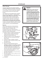
Operator Manual
SG13B / 966042601 / 2009-03
Please read the operator’s manual carefully and make sure
you understand the instructions before using the machine.
CONTENTS
INTRODUCTION................................................................ 4
Good Service............................................................... 4
Serial Number.............................................................. 4
SYMBOLS AND DECALS.................................................. 5
SAFETY............................................................................. 7
General use................................................................. 7
Preparations................................................................ 9
Operating................................................................... 10
Movement/Transport.................................................. 11
Storage...................................................................... 11
Children..................................................................... 11
Fuel System............................................................... 12
Maintenance.............................................................. 13
PROTECTION EQUIPMENT........................................... 14
Personal Protection Equipment................................. 14
SET-UP............................................................................ 15
CONTROLS..................................................................... 18
Engine....................................................................... 19
Speed Control Lever.................................................. 19
Starter........................................................................ 20
Starter Handle........................................................... 20
Fuel Valve.................................................................. 20
Choke Control............................................................ 20
Air Filter..................................................................... 21
Spark Plug................................................................. 21
Muffler........................................................................ 21
Oil Dipstick................................................................. 22
Oil Drain..................................................................... 22
Fuel Tank................................................................... 23
Fueling....................................................................... 23
Centrifugal Clutch...................................................... 23
Operator Presence (OP) Grip Bar............................. 24
Throttle...................................................................... 24
Control Panel On/Off Engine Switch.......................... 24
Brake......................................................................... 25
Handle Adjustment Bar.............................................. 25
operation.................................................................... 26
Preparation................................................................ 26
Starting The Engine................................................... 27
Handle Engine Switch............................................... 28
OP Grip Bar............................................................... 28
Starter Handle........................................................... 28
Throttle...................................................................... 28
Procedure.................................................................. 29
Operating On Hills..................................................... 31
Transport................................................................... 31
Normal Shutdown...................................................... 32
Emergency Shutdown............................................... 32
maintenance............................................................... 33
Maintenance Schedule.............................................. 33
Cyclone Filter............................................................. 34
Air Filter..................................................................... 35
Sludge Reservoir....................................................... 36
Idle Adjustment.......................................................... 37
Ignition System.......................................................... 38
Drive Belt................................................................... 39
Removing/Refitting Wheels....................................... 41
Brake Adjustment...................................................... 41
Two Minute Rule........................................................ 42
Cleaning.................................................................... 42
lubrication................................................................. 43
Engine Oil.................................................................. 44
Throttle cable............................................................. 45
troubleshooting..................................................... 46
storage........................................................................ 48
Winter Storage........................................................... 48
Service....................................................................... 48
Technical Data........................................................... 49
INTRODUCTION
Congratulations
Thank you for purchasing a Husqvarna stump grinder.
Through your confidence in us, you have chosen an
exceptionally high quality product.
This manual is a valuable document. It describes your
new Husqvarna machine. Read the manual carefully
before attempting to use the machine. Following the
instructions (use, service, maintenance, etc.) can
considerably increase the life-span of your machine
and even increase its resale value. Please contact
your dealer for more information.
If you sell your Husqvarna machine, make sure to give
the operator’s manual to the new owner.
Use
The stump grinder is used to remove tree stumps. By
moving the blade in lateral sweeping movements over
the top and front of the stump, it is gradually chipped
away. Read the chapter “Safety instructions” before
you use the machine for the first time.
This Operator’s Manual belongs to machine with
serial number:
Serial Number
The serial number can be found on the printed plate
attached to the frame in front of engine. The plate
includes the following information:
• The machine’s type designation (MODEL).
• The machine’s serial number (S/N).
Please state the type designation and serial number
when ordering spare parts.
4 - HUSQVARNA
Insure your machine
Contact your insurance company to check on
insurance coverage for your new machine. You should
have all-inclusive insurance for liability, fire, damage
and theft.
Good Service
Husqvarna’s products are sold all over the world and
only in specialized retail trade with complete service.
This ensures that you as a customer receive only the
best support and service. Before the machine was
delivered it underwent inspection and was adjusted
by your dealer. When you need spare parts or support
in service questions, guarantee issues, etc., please
consult the following professional:
Engine number:
The engine’s serial number is punched in the
crankcase under the oil level guard.
The engine type is specified on the crankcase to the
right of the oil level guard but also appears on the
decal on the starter.
Please state these when ordering spare engine parts.
symbols and decals
IMPORTANT INFORMATION
WARNING!
Xxxx xxx xxxx xx xxxx x xxxx.
Xxxx xxx xxxx xx xxxx x xxxx.
Used in this publication to notify the reader of a risk of
personal injury, particularly if the reader DOES NOT
follow the instructions given in the manual.
Used in this publication to notify the reader of a risk of
material damage, particularly if the reader DOES NOT
follow the instructions given in the manual. Used also
when there is a potential for misuse or misassembly.
Decals and machine-mounted instructions
1
2
3
4
5
7
10
6
8
11
ON
9
12
OFF
Missing or illegible decals must be replaced before using the machine.
1.
2.
3.
4.
5.
6.
Husqvarna logo
Husqvarna Crown logo
General precautions
Use ear and eye protection
Exhaust warnings
DANGER risk for injury from cutter blade
7.
8.
9.
10.
11.
12.
Model designation
Starting procedure
Throttle
Handle adjustment
No step
Handle engine switch
HUSQVARNA-5
symbols and decals
9
3
4
OFF
ON
12
5
11
10
6
Decal 3
Decal 5
Important information
Read and make sure you understand the Operator’s
Manual before use or maintenance.
To obtain a replacement manual, contact your dealer.
Observe all safety instructions; otherwise you may
injure yourself or others.
Make sure the machine is in serviceable condition
prior to use.
Stop the engine and wait until all machine movement
comes to a standstill before service, adjustment or
cleaning.
Do not run the engine in poorly ventilated spaces.
Make sure nobody is in the vicinity of the machine
before starting and during use.
Avoid slopes that are too steep to use the machine
safely.
Clear any debris prior to use.
Warning
Engine exhaust, some of its constituents and certain
vehicle components contain or emit chemicals
considered by the State of California to cause
cancer, birth defects or other reproductive harm. The
engine emits carbon monoxide, which is a colorless,
poisonous gas. DO NOT use the machine in enclosed
spaces.
Decal 4
Wear goggles or safety glasses and ear protection
when using the unit.
6 - HUSQVARNA
Decal 6
There is DANGER to your feet from the cutting blades.
Decal 9
Rabbit = Fast engage clutch.
Turtle = Slow disengage clutch.
Decal 10
Handle adjustment.
Decal 11
No step.
Decal 12
O = off, I = on
SAFETY
General use
This manual is a valuable document. Read the
contents carefully before using or servicing the
machine. The following of instructions (use, service,
maintenance, etc.) by all who operate this machine is
important for the safety of the operator and others.
It can also considerably increase the life span of the
machine and increase its resale value.
Read the manual carefully and make sure you
understand it before using the machine or performing
any maintenance. If the user cannot read this manual,
it is the responsibility of the machine owner to explain
the contents to the user.
If after reading the operator’s manual you are still
unsure about the safety risks associated with use of
the machine, you should not use the machine. Please
contact your dealer for more information.
These safety instructions only address the basics
for safe use. It would be impossible in the safety
instructions to describe all possible risk situations
that could arise when using the machine. You can,
however, prevent accidents by always using common
sense.
To obtain extra copies of the operator’s manual, please
contact your dealer.
WARNING!
Under no circumstances may the
original design of the machine be
modified without written approval
from the manufacturer. Such
modifications not only affect the
performance and durability of
the machine but may even pose
a safety risk for users and those
in the vicinity. Unauthorized
modifications to the design of
the machine may absolve the
manufacturer from liability for
any resulting personal injury or
property damage. Modifying the
machine without written approval
from the manufacturer may void the
guarantee.
IMPORTANT INFORMATION
Do not use the machine until you have
read the operator’s manual carefully and
understand the instructions given. All
maintenance work or adjustments not
described in this manual must be performed
by an authorized Husqvarna service
workshop.
Read this manual carefully before starting the machine.
8011-208c
WARNING!
The stump grinder can be
dangerous if used improperly or
without due care. This can lead
to serious accidents or, in the
worst cases, even fatal accidents.
It is very important to read this
operator’s manual and understand
the instructions before attempting
to use the machine.
HUSQVARNA-7
SAFETY
•
•
•
•
•
•
•
•
•
•
•
•
•
•
•
•
Follow all safety instructions. Failure to do so may
result in injury to yourself or others.
Accident prevention regulations, other general
safety regulations, occupational safety rules and
traffic regulations must be followed without fail.
All users shall be trained in use of the machine.
The owner is responsible for training users.
Engage an authorized Husqvarna workshop for all
service and repairs not described in this manual.
Husqvarna original spare parts are designed and
specified to maintain high quality and correct fit
for optimal durability and life-span. From a safety
point of view, use only Husqvarna original spare
parts.
Learn how to use the machine and its controls
safely and learn to recognize the safety decals.
Only use the machine for removing tree stumps. It
is not intended for any other use.
Check that the machine is in serviceable condition
prior to use; see Maintenance.
Only use the machine in daylight or in other well-lit
conditions. Keep the machine a safe distance from
holes or other irregularities in the ground. Pay
attention to other possible risks.
Only allow the machine to be used by adults who
are familiar with its use.
Never allow persons not trained in the use of the
machine to service it.
Never allow persons or children not trained in the
use of the machine to operate it. Local laws may
regulate the age of the user.
People and animals can cause distractions and
cause loss of control of the machine. Always
concentrate and focus on the task.
Never leave the machine unsupervised with the
engine running.
Make sure that other people are nearby when you
are using the machine so that you can call for help
should an emergency arise.
The machine is tested and approved only with the
equipment originally provided or recommended by
the manufacturer.
8 - HUSQVARNA
WARNING!
The engine can become very hot. To
avoid being burned, you must turn
off the engine and wait until all parts
have cooled before touching the
engine.
WARNING!
Overexposure to vibration may lead
to circulatory or nerve damage,
particularly in people who have
impaired circulation.
Contact your doctor if you
experience symptoms that could
have been caused by overexposure
to vibration. Examples of common
symptoms include numbness, pain,
muscle weakness, change of skin
color or an uncomfortable feeling of
tingling. These symptoms appear
most frequently in the fingers,
hands or wrists.
IMPORTANT INFORMATION
Never use a stump grinder that is damaged
or incorrectly adjusted. Never use the stump
grinder if any component is missing or if it
is not properly assembled. Check that the
cutting tools stop rotating when you reduce
the throttle. If you find yourself in a situation
where you are not sure what to do, always
seek expert assistance. DO NOT try to resolve
problems you are not qualified for.
SAFETY
Preparations
•
•
•
•
•
•
•
•
•
Make sure that you always have first aid
equipment at hand when using the machine.
Make sure nobody else is in the vicinity of the
machine when you start the engine, engage the
drive or run the machine.
Make sure animals and people maintain a safe
distance from the machine.
Check that the dead man’s grip and all guards are
fitted and functioning. DO NOT use the machine if
it is not working properly.
Makes sure no clothing, long hair or jewelry can
catch in moving machine parts.
Check that all safety decals are in place. See the
chapter “Location of decals”.
Use face protection, protective gloves with good
grip and protective clothing which you can move
unrestricted. Also use leg protection to protect
from sparks and the cutting tools.
Never use the machine when barefoot. Always
wear anti-slip protective shoes or protective boots
preferably with steel toes.
Use a helmet with a full face visor or a mesh visor
and protective glasses. Wear approved earprotection when running the machine. Ask your
dealer about approved protective glasses, ear
protection and recommended helmets.
Clear the work area before beginning work.
Use appropriate equipment.
8011-198
8011-189
WARNING!
Always use approved protective
clothing and approved protective
equipment when using the machine.
Protective clothing and protective
equipment cannot eliminate the risk
of accidents, but wearing proper
clothing and the correct equipment
will reduce the degree of injury
should an accident occur. Ask your
dealer about approved protective
clothing and approved protective
equipment recommended by
Husqvarna.
HUSQVARNA-9
SAFETY
Operating
•
•
•
•
•
•
•
•
•
•
•
•
Do not use the machine on grades of more than
10°.
Do not use the machine if you are tired, if you
have consumed alcohol, or if you are taking other
drugs or medication that can affect your vision,
judgment or coordination.
Never use the machine indoors or in spaces
lacking proper ventilation.
Make sure you have a proper foothold when using
the machine, particularly when backing. Walk,
don’t run. Never work on wet grass. Poor traction
may cause you to slip.
Keep your hands and feet away from moving
parts.
Keep your hands and feet away from the work
tools.
Do not use your feet or other parts of your body
to gain greater bearing pressure against the
stump.
Smoking, open flames or sparks in the vicinity
of the machine are strictly forbidden. Gasoline
is extremely flammable and carelessness in
handling can result in personal injury or fire.
Never use a machine with a defective muffler.
In very warm and dry climates, stump grinder
operation poses a risk of forest fires.
Stop and inspect the equipment if you run over or
into anything. If necessary, make repairs before
beginning again.
Whatever happens, you should always park the
machine on even ground, disengage the drive,
activate the parking, turn off the engine and wait
until all moving parts have stopped before leaving
the operating position behind the machine.
8011-209b
The engine exhaust is poisonous. Never run the engine indoors.
8011-091
Make sure you keep your hands and feet away from moving parts.
WARNING!
Engine exhaust, some of its
constituents and certain vehicle
components contain or emit
chemicals considered to cause
cancer, birth defects or other
reproductive harm. The engine
emits carbon monoxide, which is
a colorless, poisonous gas. Do
not use the machine in enclosed
spaces.
10 - HUSQVARNA
8011-291c
Smoking near the machine is strictly prohibited.
SAFETY
Movement/Transport
•
•
•
•
•
•
•
To turn and steer the machine, press down on the
handle and turn on the back wheels.
Turn off the engine and allow it to cool at least two
minutes before transport.
Fold the handle down if the machine is equipped
with a collapsible handle.
Use safe lifting and moving techniques when
loading/unloading the machine.
It is recommended that two people lift the
machine.
Activate the parking brake during transport.
Fasten the machine properly in place with
approved fasteners, such as tension belts, chains
or straps. Always check for compliance with
applicable traffic regulations before transporting
the machine.
Lift the machine with the side handles.
8011-278b
Storage
•
•
•
•
Allow the engine to cool before storing the
machine. Never store the machine near a open
flame.
Store the machine with the fuel valve closed.
Store the machine and fuel in such a way that
there is no risk that leaking fuel or fumes can
come in contact with flames or sparks from
electrical machines, electric engines, relays,
switches, boilers or similar.
Store the machine in a locked space away from
children and adults untrained in its use.
Children
Serious accidents can occur if you fail to be on guard
for children in the vicinity of the machine. Never
assume that children will stay where you last saw
them.
• Keep children away from the machine.
• Keep children away from the work area and under
close supervision by another adult.
• Shut off the machine if children enter the work
area.
• Never allow children to operate the machine.
• Be particularly careful near corners, bushes, trees
or other objects that obstruct view.
Keep children away from the machine.
Never allow children to operate the machine.
8011-207c
8011-206b
HUSQVARNA-11
SAFETY
WARNING!
Gasoline and gasoline fumes
are poisonous and extremely
flammable. Be especially careful
when handling gasoline, as
carelessness can result in personal
injury or fire.
Fuel System
•
•
•
•
•
•
•
•
•
•
Store fuel only in containers approved for that
purpose.
Never remove the fuel cap and fill the fuel tank
when the engine is running.
Always stop the engine when refueling.
Do not smoke when filling the gasoline tank and
do not pour gasoline in the vicinity of sparks or
open flame.
Never fill the fuel tank indoors.
Before starting the machine after refueling, it
should be moved at least 10 feet (3 M) from the
location where it was filled.
Turn off the fuel supply for storage or transport.
If leaks arise in the fuel system, the engine must
not be started until the problem has been resolved.
Check the fuel level before each use and leave
space for the fuel to expand. Heat from the
engine and sun can cause the fuel to expand and
overflow.
Avoid overfilling. If you spill gasoline on the
machine, wipe up the spill and wait until it has
evaporated before starting the engine. Change
garments if gasoline is spilled on clothing.
Never fill the fuel tank indoors.
Close the fuel valve.
Fueling always poses an element of risk
12 - HUSQVARNA
8011-205b
8061-024
8011-222b
SAFETY
Maintenance
•
•
•
•
•
•
•
•
•
•
•
•
•
Never make adjustments with the engine running.
Disengage the drive units, shut off the engine and
wait until all moving parts come to a complete
stop before making adjustments, performing
maintenance or cleaning the machine.
Disconnect the spark plug cable before beginning
repair work.
Keep all components in serviceable condition and
make sure all nuts, bolts and other hardware are
tight. Replace worn or damaged decals.
Be careful when checking work tools. Use gloves
when performing maintenance work.
Never allow persons not trained in the use of the
machine to perform service on it.
Always park the machine on even ground before
performing maintenance or making adjustments.
Do not disassemble the engine. This can
invalidate the engine warranty. Contact the dealer
for questions regarding service or guarantee
matters. Follow all maintenance instructions.
Do not change the setting of governors and avoid
running the engine with overly high RPM. If the
engine is run too fast, damage to the machine
components can occur.
Do not modify safety equipment. Check regularly
to be sure it works properly. The machine must
not be run with defective or disassembled safety
equipment.
The muffler is designed to maintain sound levels at
an approved level and keep direct exhaust away
from the user. Exhaust gases from the engine are
extremely hot and may contain sparks that can
cause fires or burn the user.
Never use a machine with a defective muffler.
Reduce the risk of fire by removing grass, leaves
and other debris that may have caught in the
machine.
Remove the spark plug cable.
8011-027
WARNING!
Wait until all moving parts are
completely still before performing
maintenance on the machine. Turn
off the engine and remove the spark
plug cable.
Keep the machine clean.
8011-210c
HUSQVARNA-13
Protection equipment
Personal Protection Equipment
Consult your Husqvarna dealer when selecting
protective equipment. Dealers have a broad
assortment of equipment for professionals (such as
forestry workers) and knowledge about occupational
environment requirements and protective levels.
Before using the stump grinder, you may need to
cut back the object with a power saw. It is therefore
practical to use personal protective equipment that
fulfils requirements for working with both stump
grinders and power saws.
The main difference is that you should wear protective
glasses when operating the stump grinder while the
wire mesh visor is sufficient when using a power saw.
Thus when using the stump grinder, it is recommended
to use both a wire mesh visor to protect your face
and protective glasses. A Plexiglas face guard is an
alternative, but has been found to scratch easily and is
susceptible to soiling and fogging.
You require the following personal protective
equipment:
1. Protective helmet (hard hat)
2. Ear protection
3. Face guard
4. Protective trousers
5. Protective glasses
6. Breathing protection (dusty work environment)
7. Protective gloves
8. First aid kit
9. Protective boots or steel-toed shoes
14 - HUSQVARNA
1
2
3
5
6
7
4
8
9
Personal protection equipment
8011-189
SET-UP
1.
2.
3.
4.
Remove crate top and sides.
Remove upper handle bar assembly and lay aside.
Open bag containing loose hardware.
Using four (4) screws, flat washers and nuts attach
the upper handle bar assembly to lower handle
bar assembly.
NOTE: Handle fit is tight. When aligning holes use
a tapered type pilot to help align holes (i.e. punch
or phillips style screw driver).
5. Attach the position adjusting rod to bracket on the
upper handle bar assembly with the washers and
cotter pins placed above the rod bracket. Attach
the lower adjustment bar to the unit and secure
with cotter pin.
6. Assemble the compression spring, two (2) flat
washers and yoke to brake rod assembly.
7. Screw yoke onto the rod assembly until rod is
even or through threaded portion of yoke about ¼"
(6.35 mm).
UPPER HANDLE BAR
WASHERS
COTTER PINS
ADJUSTING ROD
LOWER
HANDLE BAR
WASHERS
NUT
SPRING
YOKE
8. Attach brake rod assembly to brake handle on the
upper handle bar assembly.
BRAKE ROD ASSEMBLY
BRAKE
HANDLE
HUSQVARNA-15
SET-UP
7. Set the brake rod assembly into the brake bracket.
The brake rod assembly needs to be adjusted
before connecting the yoke to the brake. Turning
the yoke clockwise shortens the rod, tightening
the grip on the brake disc by the brake pads.
Counterclockwise loosens the clamping force.
8. After adjustment, attach the yoke to the brake’s
top mounting hole using the clevis pin and cotter
pin.
9. Turn the adjustment nut against the spring and
washer until the spring set snugly against the
brake bracket and has a small amount of tension.
With proper brake adjustment, the wheel will slide,
but not turn, when the handle is over center.
To engage brake, pull back on the handle until
brake rod assembly goes “over center” and locks
the brake ON. Test for proper tension and grip.
ADJUSTMENT NUT
CLEVIS PIN
HAIR PIN
10. Remove air cleaner and double wire clamp from
engine.
CLAMP
11. Route the wire harness from engine and the throttle
cable through guide and handle crossmember.
12. Connect upper and lower wire harness together,
yellow to yellow—black to black.
THREAD WIRE HARNESS
AND THROTTLE CABLE
GUIDE
16 - HUSQVARNA
BRAKE BRACKET
SET-UP
13. Push throttle control lever on console forward to
full extent. Pull throttle control lever on engine
back as far as possible. Insert “L” end of throttle
cable into the outside hole of the engine throttle
control lever.
14. Attach the throttle cable to the engine using the
double wire clamp removed previously.
ENGINE
THROTTLE
CONTROL LEVER
THROTTLE
CABLE
FORWARD
15. Test throttle control by pulling back throttle handle
on console. Throttle arm on engine should be
pushed completely forward. Cable should not slip
in clamp when doing this test.
16. Test proper wire length by pulling on the handle
adjustment lever and raising and lowering the
handle to maximum position without any pull on
harness.
17. Reattach air cleaner to engine.
18. Remove unit from pallet.
THROTTLE
CABLE
HUSQVARNA-17
CONTROLS
Main Components and Controls
5
7
8
9
10
6
4
5
8
3
11
2
1
8064-005
1.
2.
3.
4.
5.
6.
Handle
Operator Presence Grip Bar
Brake Lever
Cutter Drive Belt Guard
Front Lifting Handles
Cutting Wheel
18 - HUSQVARNA
7. Engine
8. Rear Lifting Handles
9. Handle Adjustment Bar
10. Throttle
11. Engine Switch
CONTROLS
Engine
Exterior engine components and controls.
1. Speed control lever
2. Starter handle
3. Air filter
4. Muffler
5. Fuel Valve
6. Choke control
7. Oil drainage
3
1
4
2
6
5
7
8011-126
8. Oil dipstick
9. Oil level guard
10. Fuel tank
11. Fuel filler cap
11
10
9
8
8011-273
Speed Control Lever
The speed control lever on the engine is normally not
used. It is connected to the throttle on the handle. If
the cable should bind or break, you can reduce the
throttle with the lever on the engine as an emergency
measure to slow the engine speed to an idle and stop
the cutting wheel.
8011-034
HUSQVARNA-19
CONTROLS
Starter
The magnapull-type starter has spring return. To
replace the return spring or starter cord, contact an
authorized service workshop.
IMPORTANT INFORMATION
Do not let the recoil cord snap back by itself.
This may damage the cord or the recoil
starter assembly.
Starter Handle
Misuse of the starter handle can damage the starter.
Do not twist the starter cord around your hand.
Pull out the handle slowly until the gears mesh. Do not
pull out the starter cord completely and do not let go of
the starter handle when extended.
8011-127
Fuel Valve
The fuel valve opens and closes the connection
between the tank and the carburetor. The illustration
shows the tank valve closed; to open, turn the lever
completely to the right. There is no middle position.
Turn off the valve when the machine is not in use
to avoid flooding the carburetor. The fuel valve is
combined with a sludge reservoir.
WARNING!
Do not run the engine indoors, in
enclosed or poorly ventilated spaces.
Engine exhaust fumes contain
poisonous carbon monoxide.
8060-024
Choke Control
The choke control opens and closes the choke valve in
the carburetor. This is only used to start a cold engine.
If the engine is warm, the control should be in the far
right position.
If the engine is cold, place the lever completely or
partly to the left. Move the lever back to the right once
the engine starts. Forgetting the choke is evident if the
engine runs roughly and produces black smoke.
This also results in increased fuel consumption.
8060-024
20 - HUSQVARNA
CONTROLS
Air Filter
The engine air filter consists of a cyclone filter and a
fine filter.
Air is drawn in through the screen (1) on the cyclone
filter and coarser pollutants collect in the container (2).
The fine filter, consisting of a foam rubber pre-filter and
a paper filter cartridge, is located under the cowling
(3). The cowling and the cyclone filter can be removed
by removing the wing nut (4).
See Replacing the Air Filter in the Maintenance section
for cleaning instructions.
Running the machine with a dirty air filter will cause
the engine to run on partial choke and show the same
symptoms as a closed choke described above. It can
also be difficult to start.
3
4
2
1
8011-126
Spark Plug
The engine spark plug is hidden under the ignition
cable boot. When performing service, it is important
that the engine cannot start accidentally. For this
reason, always remove the ignition cable boot from the
spark plug. To avoid pulling the cable, the cable boot
is equipped with a special handle; see the illustration.
See Technical Data for replacement specifications.
Muffler
WARNING!
The engine and the exhaust system,
become very hot during operation.
8011-027
Risk for burns if touched.
Allow engine and exhaust system to
cool at least two (2) minutes before
refueling
The engine muffler is equipped with a heat protective
cowling but still becomes hot when the engine is
running. Avoid touching the muffler when it is warm.
There is a risk for burns.
HUSQVARNA-21
CONTROLS
Oil Dipstick
The dipstick for the crankcase oil reservoir is located
on the front of the engine. Refill the engine oil in the
hole where the dipstick fits.
When checking the oil level, the dipstick should not
be screwed in. The machine should be parked on
even ground with the engine stopped. Never run the
engine without the dipstick in place. The engine has
an electronic oil level guard. It stops and cannot be
started if the level becomes too low. Yet you should
not rely entirely on the level guard; rather you should
check the oil using the dipstick.
For normal use, SAE 10W-30 weight engine oil service
SF-SG is recommended; see also Lubrication.
8011-020
Oil Drain
The drainage screw for the crankcase oil reservoir is
located on the back of the engine.
IMPORTANT INFORMATION
Used engine oil is a health hazard and
legislation prohibits disposal on the ground
or in nature; it should always be disposed
of at a workshop or appropriate disposal
location. Avoid skin contact; wash with soap
and water in case of spills.
8011-187
22 - HUSQVARNA
CONTROLS
Fuel Tank
Underneath the tank, there is a fuel filter combined
with the fuel valve. Tank capacity is 1.72 gallons (6.5
liters)
Fueling
Read the safety instructions before fueling.
Keep the fuel and fuel tank clean. Avoid filling the
machine with dirty fuel. Make sure the fuel cap is
properly tightened and the gasket is not damaged,
particularly before washing the machine.
Use unleaded gasoline with minimum 86 octane rating.
Never use gasoline mixed with two-cycle oil. For
ethanol and methanol fuel, the following applies:
Maximum allowable ethanol 10% (volume).
Maximum allowable methanol 5% (volume).
Maximum allowable MTBE (Methyl Tertiary Butyl
Ether) 15% (volume).
If the engine jerks at normal load it can be damaged.
Change the fuel. If this does not help, contact an
authorized service workshop.
Do not fill the tank completely; leave space for the fuel
to expand as it warms up.
Use clean, fresh fuel
8011-222b
WARNING!
Gasoline is highly flammable.
Observe caution and fill the tank
outdoors (see the safety instruction).
Centrifugal Clutch
The engine is equipped with a centrifugal clutch that
is connected to the crankshaft. When the engine
speed increases, the drive for the cutting wheel
engages automatically. The centrifugal clutch is
maintenance-free; it is not possible for the user to
make adjustments.
8011-247
HUSQVARNA-23
CONTROLS
Operator Presence (OP) Grip Bar
The bar must be held against the handle for the engine
to run. If the grip is released, the ignition system shortcircuits and the engine stops.
WARNING!
Do not over-ride the safety system
by binding the bar to the handle.
Throttle
The lever controls engine speed.
With the lever down, the engine runs at idle and
functions as start position.
When the engine speed increases, the centrifugal
clutch drive automatically engages the cutting wheel.
Control Panel On/Off Engine Switch
The ON/OFF engine switch can be used to stop the
engine. The illustration shows the toggle switch in the
OFF position (short circuited electrical system).
A second switch with the same function is activated by
the OP grip bar.
To start the engine, the control panel switch must be
set to the ON position and the OP grip bar must be
held in.
24 - HUSQVARNA
ON
OFF
CONTROLS
Brake
The lever activates a disk brake on the left wheel
when it is pulled backwards. The brake should always
be activated when the grinder is parked, is being
transported or when it is in operation
WARNING!
NEVER operate a machine with a
defective brake.
WARNING!
To avoid the risk of losing control
of the machine, DO NOT pull out the
adjustment bar when the cutting
wheel is rotating.
Handle Adjustment Bar
As the tree stump is ground away, the handle position
will need to be adjusted. Pull the handle backwards
and set the handle at a suitable working height.
Engagement rods are spring loaded to insure positive
locking when released, but always make sure bolts are
locked into place after adjustments are made.
HUSQVARNA-25
operation
Preparation
•
•
•
Dig away the earth and remove any stones near
the tree stump that may interfere with your work.
Check that the ground is free of foreign objects,
such as electrical cables, barbed wire, etc.
Cut or trim the stump as necessary using a power
saw.
Review all of the machine’s safety decals.
8011-141
•
Use a hard hat, ear and eye protection. A mesh
visor alone does not provide sufficient eye
protection; supplement with protective glasses.
8011-191
•
•
•
•
•
Make sure that you are familiar with safety
regulations and shutdown procedures described
previously in the operator’s manual.
Make sure that all guards are in place and in good
condition.
Make sure that the blades and cutters are in place
and in good condition.
Make sure that the work area and cutter in
particular and free from metallic objects such as
wire, nails, etc. that could be thrown out and injure
persons in the vicinity and damage the equipment.
Make sure that everyone, including children and
animals, maintains a distance of at least 50 feet
(15 M) from the machine. Debris can be thrown
out and injure people and animals.
26 - HUSQVARNA
8011-193
operation
Starting The Engine
Check that all daily maintenance as described in the
maintenance schedule has been performed. Check
that there is sufficient fuel in the tank.
Fuel valve
Open the fuel valve. Push the lever fully to the right.
8060-024
Choke control
When starting the engine warm, the lever should be in
the right position; see the illustration.
When starting the engine cold or partially warm, place
the lever completely or partly to the left. Move the lever
back to the right once the engine starts. When the
engine is cold, it may be best to move the lever back
in several stages. Find the position where the engine
runs smoothly.
8060-024
Throttle
Set the throttle on the handle to the SLOW (START) /
DISENGAGE position.
HUSQVARNA-27
operation
Handle Engine Switch
Set the toggle switch to ON.
Engine ON/OFF Switch
The switch on the engine is disconnected. Use the
Handle Engine Switch.
ON
OFF
8060-026
OP Grip Bar
Hold in the bar for the OP grip bar against the handle.
8060-029
Starter Handle
The OP grip bar must be held against the handle when
starting the engine.
Misuse of the starter handle can damage the starter.
DO NOT twist the starter cord around your hand.
Pull out the handle slowly until the gears mesh. Then
give a sharp pull on the starter handle. DO NOT pull
out the starter cord completely and DO NOT let go of
the starter handle when extended. Return the handle
to the recoil position.
Throttle
Keep the throttle at idle. When the throttle is increased,
the cutting wheel will begin rotating.
8011-127
28 - HUSQVARNA
operation
Procedure
WARNING!
NEVER allow the blade to touch the
ground until it has stopped turning
1. Place the cutting blade near the top front edge of
the tree stump.
2. Set the brake to lock position.
8011-201c
3. Set the throttle to SLOW (START) DISENGAGE.
4. Set engine switch on handlebar to ON.
ON
OFF
8060-026
HUSQVARNA-29
operation
5. Tilt the machine on its wheels, lifting the cutting
wheel off the ground.
6. Hold in the OP grip bar and start the engine.
7. Allow the engine to warm up for two minutes at
idle before grinding.
8060-200
8. Set the handle throttle to FAST to engage clutch.
8060-027
9. Place the middle of the cutting wheel
approximately 1" (2.5 cm) above and ¾" to 1½"
(2-4 cm) into the stump.
10. Place the cutting wheel in the upper front edge of
the stump. Swing the cutting wheel from side to
side while lowering it about 1" (2.5 cm) after each
pass until the front edge of the stump is gone.
IMPORTANT INFORMATION
If the cutting wheel is too low, the machine
may start to “climb” over the stump and
become unstable.
8011-203a
30 - HUSQVARNA
operation
11. Before moving the machine forwards, you should
ensure that the cutting wheel is above the ground
and located on either side of the stump. Move the
machine forward by releasing the brake, pushing it
forward, activating the brake again and repeating
Steps 9 and 10.
12. Repeat Steps 9 through 11 until the upper portion
of the stump has been removed. DO NOT cut
deeper than ground level at this stage.
13. Set the throttle to SLOW/(START) DISENGAGE
and wait until the cutting wheel stops rotating.
14. Release the brake and pull the machine away from
the stump.
15. It may be necessary to clear wood chips from the
area around the stump.
16. If you want to grind below the ground level, it may
become necessary to adjust the handle position to
achieve a better hand and arm work position. Pull
the handle control lever and adjust the handle to
the desired position.
17. Repeat Steps 6 through 10 until you reach the
desired depth.
18. Shut off the machine when you are done.
OFF
ON
Operating On Hills
Be very careful when operating the stump grinder
on hills because the machine can slip or move
unexpectedly.
NEVER use the machine on grades of 10° or steeper.
Transport
The Husqvarna stump grinder can be transported in a
truck, trailer, van or a large SUV (Sport Utility Vehicle).
The stump grinder is equipped with four lifting handles
(two on each side) so that two people can lift the
machine if necessary.
DO NOT attempt to lift the machine alone. Use safe
lifting techniques and DO NOT exceed your physical
limitations.
Secure the machine with tensioning belts, chains or
other approved materials.
The lifting handles can also be used to secure the machine
for transport.
HUSQVARNA-31
operation
Normal Shutdown
Throttle
Set the throttle to SLOW/DISENGAGE.
If the engine has been running full out, let it run easily
for about 30 seconds to 1 minute at low speed.
DO NOT let front of unit touch ground until you are
sure cutting wheel has stopped turning.
Engine switch
Wait at least 20 seconds, until the blade has stopped.
Set the toggle switch to OFF.
Make sure that the blade is resting against the ground
and has stopped completely before doing anything.
Brake
Activate the brake by pulling the lever backwards.
ON
OFF
Fuel valve
Close the fuel valve. Turn the lever all the way to the
left.
Emergency Shutdown
Release the OP grip bar. Wait until the blade stops.
Make sure that the blade is resting against the ground
and has stopped completely before continuing.
8060-024
32 - HUSQVARNA
MAINTENANCE
Maintenance Schedule
WARNING!
The following is a list of maintenance procedures
that MUST be performed on the machine. For those
points not described in this manual, visit an authorized
service workshop.
No service operations may be
performed on the engine or unit
unless:
The engine is stopped.
The ignition cable has been removed
from the spark plug.
The machine is securely parked
where it will not tip or begin rolling.
MAINTENANCE INTERVALS - MONTHS/HRS
Daily
-/10
1/25
3/50
6/100
12/300
MAINTENANCE
Check engine oil level
Change engine oil
n
1)
n
Check air filter
Clean air filter
n
2)
n
Replace air filter cartridge
2)
n
Clean sludge reservoir for fuel system
n
Check and clean spark plug
n
Replace spark plug
n
Check engine switch function
3)
n
Check idle speed
n
Check and adjust play in valves
Clean fuel tank
4)
n
4)
n
Check, replace fuel lines as necessary
Check throttle and cable
Check blade and cutter
4, 5)
3)
n
n
3)
n
Check decals and warning signs
3)
n
Check wear and tension on belts
3)
n
Check chassis, bolts and set screws
Grease the blade bearings (use high temperature grease
such as Mobilith SHC 220 or equal)6)
n
n
Grease the wheels (standard lithium base)
Check tire air pressure (25 psi max)
n
n
1)
First change after 20 hours. 2)In dusty conditions maintenance is required at shorter intervals. 3)Before each use.
4)
Performed by authorized service workshop. 5)Performed every second year. 6)Grease every 4 hours.
HUSQVARNA-33
MAINTENANCE
Cyclone Filter
The cyclone filter collects the largest contaminant
particles, which collect in the container. When you can
see a layer of dirt at the bottom of the container, the
cyclone housing (1), air channels and air intake screen
(2) must be cleaned.
1
2
8011-126
Remove the three screw holding the cyclone housing.
Remove the housing with the air intake screen and
remove the air channels.
The air channels may remain in the upper portion or
follow along with the housing when removed.
IMPORTANT INFORMATION
Exercise care when reassembling to avoid
damage.
Make sure when mounting that the air intake
screen fits exactly in its guide in the upper
portion.
Make sure the air channel ends up in the
proper position.
8011-213
Clean the components, using warm water, mild
detergent and a sift brush. Dry carefully.
Refit the components. Place the air channels in the
cyclone housing. Insert cyclone housing into position
and make sure it fits in the upper portion. DO NOT
use force; rather coax it into place before refitting the
screws.
8011-212
34 - HUSQVARNA
MAINTENANCE
Air Filter
If the engine seems weak, produces black smoke or
runs unevenly, the air filter may be clogged. For this
reason, it is important to clean and replace the air filter
regularly (see the maintenance schedule for the proper
service interval).
WARNING!
Allow the exhaust system to cool
before performing service. Risk for
burns.
For cleaning or replacement:
1. Undo the wing nut (1) and lift off the cyclone filter
with the air filter cowling (2).
1
2
8011-126
2. Remove the foam rubber pre-filter and clean using
a mild detergent. Squeeze dry with a clean cloth.
Soak it with new engine oil. Wind the filter in an
absorbent cloth and squeeze out excess oil.
8011-030
HUSQVARNA-35
MAINTENANCE
3. Remove the wing nut in the air filter and remove
the paper filter.
IMPORTANT INFORMATION
DO NOT use compressed air over 2 bar/30 PSI
to clean the paper filter.
DO NOT wash the paper filter.
DO NOT oil the paper filter.
8011-031
4. Tap the paper filter against a fixed surface to
remove dust. If the paper filter is still dirty or
damaged, it must be replaced.
5. Mount the paper filter in the air filter housing and
tighten the wing nut.
6. Refit the pre-filter on the paper filter.
7. Refit the cyclone filter with the air filter cowling.
8011-032
Sludge Reservoir
1. Close the fuel valve.
8060-024
36 - HUSQVARNA
MAINTENANCE
2. Unscrew the sludge reservoir (1). Make sure not to
misplace the o-ring (2).
3. Clean the reservoir and the o-ring using a cleaning
solvent and dry carefully.
4. Put the o-ring in place in its track and replace the
sludge reservoir. Tighten it moderately to avoid
damaging the threads.
5. Turn the fuel valve to ON and check for leaks. If it
leaks, replace the o-ring.
1
2
8011-128
Idle Adjustment
WARNING!
Risk for carbon monoxide poisoning.
Perform the adjustment outdoors.
1. Start the engine and run it until it reaches normal
working temperature.
2. Adjust the throttle to idle position or so that the
engine runs at the lowest possible speed.
3. Turn the idle screw so that the engine idles at
1250-1550 RPM.
4. Increase the idle speed with the throttle and move
it right back to idle position. Check engine speed
again.
8011-128
HUSQVARNA-37
MAINTENANCE
Ignition System
The engine is equipped with an electronic ignition
system. Only the spark plug requires maintenance.
For recommended spark plug, see “Technical data”.
IMPORTANT INFORMATION
Fitting the wrong spark plug type can damage
the engine.
1. Remove the ignition cable shoe and clean around
the spark plug.
2. Remove the spark plug with a 13/16" (21 mm) spark
plug socket wrench.
3. Check the spark plug. Replace the spark plug if the
electrodes are burned or if the insulation is cracked
or damaged. Clean the spark plug with a steel
brush if it is to be reused.
4. Measure the electrode gap with a gapping tool.
The gap should be 0.7-0.8 mm/0.028-0.031".
Adjust as necessary by bending the side electrode.
5. Reinsert the spark plug, turning by hand to avoid
damaging the threads.
8011-027
IMPORTANT INFORMATION
Inadequately tightened spark plugs can
cause overheating and damage the engine.
Tightening the spark plug too much can
damage the threads in the cylinder head.
6. After the spark plug is seated, tighten it using
a spark plug wrench so that the washer is
compressed. A used spark plug should be turned
1/8-¼ of a turn from the seated position. A new
spark plug should be turned ½ a turn from the
seated position.
7. Replace the ignition cable shoe.
38 - HUSQVARNA
8011-054
MAINTENANCE
Drive Belt
1. Remove the belt guard by removing the three
acorn nuts and lockwashers on the front of the belt
guard.
WARNING!
Prevent the engine from being
started by removing the ignition
cable from the spark plug.
8060-226
2. Check that the belt is properly tensioned by
squeezing the belt together. It should be possible
to squeeze the belt down about ¼ - 3/8" (6 - 10
mm) from the original position.
3. Loosen screws holding cover plate to belt guard
backing plate.
8060-227
4. Undo the two screws (A) on each side of the
cutting shroud.
COVER PLATE
SCREWS
8062-006
HUSQVARNA-39
MAINTENANCE
5. Loosen the locking nuts (B) on the two tension
bolts.
6. Turn the two tension bolts (C) counter-clockwise to
loosen the belt or clockwise to tighten it.
A
C
B
IMPORTANT INFORMATION
If pulley on cutter head shaft must be moved,
the set screws MUST be fully removed, fresh
“Loctite 242” put on threads and re-torqued to
100 - 110 in./lbs. (17513 / 19264 N•m).
7. Check that the pulleys are aligned using a straight
edge along the inside face of the clutch and pulley.
Pulleys must be inline. Maximum gap or misalignment is 1/16" (.062) or 15.7 mm. Adjust using
the tension bolts as necessary. Check belt tension
again.
8. Tighten all screws and nuts when the adjustment
is complete. Be certain cover plate is not rubbing
against cutter wheel shaft.
9. Refit the belt guard.
8011-228
CHECK CLUTCH &
PULLEY ALIGN
USING INSIDE FACE
8011-229
Cutting Wheel
WARNING!
The cutters can come loose from
the cutting wheel if the bolts are not
sufficiently tight. Comply with the
recommended torque settings.
Tighten the screws 30 ft/lbs. (133 Nm).
40 - HUSQVARNA
TOOTH CUTTER
(CARBIDE FACE)
MAINTENANCE
Removing/Refitting Wheels
Left Wheel
To remove the left wheel (1) from the stump grinder,
remove the locking collar (2), the ¼" screws (3), the
¼" hex nuts (3), the springs (4) and the brake pad (5).
The wheel can now be removed from the axle.
Right Wheel
To remove the right wheel (6), remove the locking
collar (7) and slide the wheel off the axle.
6
7
RIGHT
FRONT
3
LEFT
4
5
3
2
1
8011-217
Brake Adjustment
Overcentering type handle activities brakes.
Undo clevis pin from brake and turn clockwise to
tighten brake or counter clockwise to loosen.
Tighten so handle snaps down when locked but
unlocks easily when handle is moved forward. Brake
is properly adjusted when wheel will not turn when you
try to push or pull unit.
CLEVIS PIN
HAIR PIN
HUSQVARNA-41
MAINTENANCE
Two Minute Rule
The machine may be tipped backward or on its side to
facilitate access for cleaning or service, but no longer
than 2 minutes.
If the machine is held in this position for too long, the
engine can be damaged by gasoline draining into the
crankcase. Should this happen, perform an extra oil
change on the engine. Remove the spark plug and
turn the engine over a few revolutions with the starter
handle before starting the engine again.
8064-007
Cleaning
Regular cleaning and washing will increase the
machine’s lifespan. Make it a habit to clean the
machine directly after use, before the dirt sticks.
Check before rinsing that the fuel tank lid is properly in
place to avoid getting water in the tank.
Use caution when using high-pressure spray because
warning decals, instruction signs and the engine can
be damaged. Do not exceed 70 bar/1000 PSI water
pressure when cleaning.
Lubricate the machine after cleaning. This is
particularly important if the machine is to be stored.
8011-210c
42 - HUSQVARNA
LUBRICATION
HUSQVARNA-43
LUBRICATION
Engine Oil
The engine should be warm (but not hot) when
changing the oil. Warm oil flows out faster and leaves
a smaller quantity of old oil inside the engine.
1. Place a suitable container underneath the oil
drainage screw. Remove the oil dipstick and the oil
drainage screw on the back surface of the engine.
Tip: Make a channel using a piece of cardboard
to lead the oil directly into the container to avoid
soiling the machine chassis.
2. Allow the engine oil to drain into the container;
then replace the drainage screw. Tighten it
moderately.
WARNING!
Engine oil can be very hot if it is
drained directly after stopping the
machine. Allow the engine to cool for
approximately 2 minutes.
IMPORTANT INFORMATION
Used engine oil is a health hazard and
legislation prohibits disposal on the ground
or in nature; it should always be disposed
of at a workshop or appropriate disposal
location. Avoid skin contact; wash with soap
and water in case of spills.
3. Make sure the machine is parked on flat ground.
Fill with new oil using the appropriate viscosity
according to the diagram, API Service SF-SG,
to the upper level mark on the dipstick = threads
on the oil dipstick. The engine takes 1.16 qts.
(1.1 liters) of oil. When checking the oil level, the
dipstick should not be screwed in.
4. Check that the rubber gasket is in position and
screw the dipstick back into place. Do not
tighten it askew or too hard or you may damage
the threads.
5. Wipe up any spilled oil.
8011-187
8060-028
8011-046
44 - HUSQVARNA
LUBRICATION
Checking Engine Oil Level
Make sure that the machine is parked on flat ground
with the engine stopped when checking the oil level.
1. Unscrew the dipstick and wipe it using paper towel
or a lint-free rag.
2. Replace the dipstick without screwing it in.
Remove and check the level on the dipstick.
3. Fill oil as necessary to the lip of the dipstick hole.
Oil type, see above.
4. Check that the rubber gasket is in position and
screw the dipstick back into place. DO NOT
tighten it askew or too hard or you may damage
the threads.
8011-020
Right wheel
Lubricate using a grease gun until the grease
squeezes out one nipple.
Use good quality MP grease. Grease from well-known
brand names (petrochemical companies, etc.) usually
maintains a good quality.
8011-231
Throttle cable
Peel back the rubber covers at both of the cable
mountings. Grease both ends of the throttle cable
and move the controls to end stop positions when
lubricating. Refit the rubber covers on the cable after
lubrication. Cables with sheaths will bind if they are
not lubricated regularly. Binding in a cable may cause
malfunction.
If the cable binds, remove the cable and hang it
vertically. Lubricate it with thin engine oil until the oil
begins to escape from the bottom.
Tip: Fill a small plastic bag with oil and tape it so that
it seals against the casing and allow the cable to hang
vertically from the bag overnight. If you do not succeed
in lubricating the cable, it must be replaced.
8011-234
HUSQVARNA-45
TROUBLESHOOTING
PROBLEM
CAUSE
ACTION
User error
Fuel valve closed
Choke valve open
Engine switch in OFF position
Open the fuel valve
Close the choke with cold engine
Turn the engine switch to ON
Fuel system
Fuel tank empty
Machine stored without observing
proper procedure from chapter
“Storage/Winter storage”
Contamination, water or ice in fuel
system
Fill with fuel
Clean tank, sludge reservoir and
empty carburetor, fill the tank with
fresh fuel
Clean tank, sludge reservoir and
empty carburetor, fill the tank with
fresh fuel
Contact an authorized service
workshop
Engine will not start
Carburetor problems
Spark plug
Wrong spark plug type
Build-up on electrodes, short circuit
Loose spark plug
Replace the spark plug
Check electrode gap and clean or
replace spark plug
Clean the spark plug, air the engine
out and start with full throttle
Check spark plug connection
No spark after checking spark plug
Faulty engine switch, cable or
ignition
Contact an authorized service
workshop
Low compression
Serious interior engine damage or
faulty valves
Contact an authorized service
workshop
Air filter
Clogged air filter
Clean or replace the air filter
Fuel system
Machine stored without observing
proper procedure from chapter
“Storage/Winter storage”
Clean tank, sludge reservoir and
empty carburetor, fill the tank with
fresh fuel
Blue or blue-white exhaust
Contaminated or incorrect fuel
Clean tank, sludge reservoir and
empty carburetor, fill the tank with
proper fuel
Black exhaust
Choke left on
Clogged air filter
Carburetor problems
Open choke valve
Clean or replace the air filter
Contact an authorized service
workshop
Ignition system
Wrong spark plug type
Build-up on electrodes, short circuit
Replace the spark plug
Check electrode gap and clean or
replace spark plug
Contact an authorized service
workshop
Gasoline or oil on the spark plug
Engine is weak or runs unevenly
Faulty ignition unit
Low compression
46 - HUSQVARNA
Serious interior engine damage or
faulty valves
Contact an authorized service
workshop
TROUBLESHOOTING
PROBLEM
CAUSE
ACTION
Pulleys not aligned
Adjust belt tension
Belt comes off
Belt tension is insufficient
Belt engages late or slips
Tighten the belt as described in the
operator’s manual
Reduce cutting depth
Belt not staying tight after adjustment
Damaged axle, pulley or key
Replace damaged parts
Make sure the setscrews are
properly tightened
Cutting wheel does not rotate
Engine speed is insufficient to
activate the centrifugal clutch
Belt tension is insufficient
Clutch is worn
Cutting wheel continues to rotate
Make sure the throttle cable is
working properly
Adjust belt tension
Replace shoes and springs, and/or
clutch bearings
The engine speed is not under 1000 Check for damage on the throttle
rpm, which is required to disengage cable
the centrifugal clutch
Check that the throttle cable is
properly mounted on the throttle
valve
Inspect springs on clutch shoes,
if tension on clutch shoes is not
enough to pull shoes back, replace
springs and clutch shoes
Parking brake slips
Adjust the brake tension in the
manner described in the
operator’s manual
Check for damage on the brake rod
or lever
Check for wear on the brake pads.
replace as necessary
HUSQVARNA-47
Storage
Winter Storage
At the end of the season, the machine should be
readied for storage (or if it will not be in use for longer
than 30 days). Fuel allowed to stand for long periods
of time (30 days or more) can leave sticky residues
that can plug the carburetor and disrupt engine
function.
Fuel stabilizers are an acceptable option as regards
sticky residues during storage. If alkylate gasoline
(Aspen) is used, stabilizers are unnecessary because
this fuel is stable. However, you should avoid
switching between regular and alkylate gasoline
as sensitive rubber components can harden. Add
stabilizer to the fuel in the tank or in the storage
container. Always use the mixing ratios specified by
the manufacturer of the stabilizer. Run the engine for
at least 10 minutes after adding the stabilizer so that it
reaches the carburetor. DO NOT empty the fuel tank
and the carburetor if you have added stabilizer.
WARNING!
NEVER store an engine with fuel
in the tank indoors or in poorly
ventilated spaces where fuel vapor
can come in contact with open flame,
sparks or a pilot light such as in a
boiler, hot water tank, clothing drier,
etc. Handle the fuel with caution. It
is very flammable and careless use
can cause serious damage to person
and property. Drain the fuel into an
approved container outdoors and
far away from open flame. NEVER
use gasoline for cleaning. Use a degreaser and warm water instead.
Service
When ordering spare parts, please specify the
purchase year, model, type, and serial number.
Always use genuine Husqvarna parts.
An annual check-up at an authorized service
workshop is a good way to ensure that your machine
performs its best the following season.
To ready the machine for storage, follow these steps:
1. Clean the machine carefully, particularly the
chassis and working equipment. Touch up
damage to the paint to prevent rust.
2. Inspect the machine for worn or damaged parts
and tighten any nuts or screws that may have
become loose.
3. Change the engine oil; dispose of properly.
4. Open the fuel valve. Empty the fuel tank (1) and
the carburetor (2).
5. Close the fuel valve.
6. Remove the spark plug and pour about a
tablespoon of engine oil in the cylinder. Turn over
the engine so that the oil is evenly distributed and
then refit the spark plug. Put the engine in the
compression phase where the triangle mark on
the sleeve of the starter is aligned with the upper
hole in the starter. Note: Compression phase
occurs every second revolution.
7. Lubricate all grease nipples, joints and cables as
described in Lubrication.
8. Store the machine in a clean, dry place and cover
it for extra protection.
9. Cover the blade and cutters with a thin coat of oil
to avoid rust.
48 - HUSQVARNA
2
1
8011-130
8011-131
TECHNICAL DATA
Model SG13B / 966042601
Engine
Manufacturer
Cylinder Volume
Honda
337 cc (20.6 cu in)
Power
13 hp (9.2 kW at 3600 RPM)*
Torque
17.36 ft-lb / 2.4 kg-m at 2500 RPM
Idling speed
Oil capacity including filter
Spark plug
Fuel tank volume
1250-1550 RPM
2.2 qt / 2.1 liter
NGK BP6ES or BPR6ES
1.7 gal. / 6.5 L
Chassis
Tires
4.10-6 (12" pneumatic)
Brake
Disk - Lever activated
Drive
Direct
Belt
Clutch
Cutting Wheel
Cut Depth
Dayco double V-belt
Amsbeck or Noram centrifugal clutch
14" dia. x 3/8" thick disc (157.5 mm x 9.5 mm)
Approx 10" (25.4 cm)
Dimensions
Length
62"- 73" (157- 185 cm) depending on handle position
Width
27" (69 cm)
Height
24"- 43" (61 - 109 cm) depending on handle position
Weight
249 lb. (112.9 kg)
HUSQVARNA-49
schematics
ON/OFF
SWITCH
SAFETY
SWITCH
ENGINE ON/OFF
SWITCH
(DISCONNECTED)
SPARK
PLUG
TRANSISTOR
IGNITION
OIL LEVEL
GUARD
8064-008
ENGINE HARNESS
CONSOLE HARNESS
ENGINE ON/OFF
SWITCH
(DISCONNECTED)
COLOR CODE
Y - YELLOW
B - BLACK
TRANSISTOR
IGNITION
SPARK
PLUG
ON/OFF
SWITCH
MODULE
SAFETY
SWITCH
OIL LEVEL
GUARD
50 - HUSQVARNA
8064-009
SERVICE JOURNAL
Action
Date, stamp, signature
Delivery service
1. Open packaging and make sure machine has not been damaged in
transport.
2. Where applicable, assembly accompanying components.
3. Check that machine design corresponds to customer order.
4. Check that right amount of oil is in engine and transmission.
5. Check and adjust air pressure in tires. (25 psi max.)
6. Check that working equipment is properly set.
7. Check drive pulleys and sprockets for alignment.
8. Check belts and chains for proper adjustment.
9. Lubricate the machine as described in the lubrication schedule.
10. Fill fuel tank and start engine.
11. Check that machine and working equipment do not move in neutral.
12. Check all operating instruments.
13. Check decals and information attached to unit.
14. Check engine speed (RPM), see Technical Data.
15. Check for leakage.
16. Inform the customer about:
The need and advantages of following the service schedule.
The need and advantages of leaving the machine for service every
300 hours.
The effects of service and maintaining a service journal on the
machine’s resale value.
17. Fill in the sales papers, etc.
Delivery service has
been carried out.
No remaining notes.
Certified:
After the first 20 hours
1. Change engine oil.
2. Change oil in reduction gear, where applicable.
3. Check that belts and chains are properly adjusted.
4. Tighten screws and nuts.
HUSQVARNA-51
SERVICE JOURNAL
Action
52 - HUSQVARNA
Date, stamp, signature
SERVICE JOURNAL
Action
Date, stamp, signature
HUSQVARNA-53
SERVICE JOURNAL
Action
54 - HUSQVARNA
Date, stamp, signature
HUSQVARNA PRODUCT REGISTRATION INFORMATION & WARRANTY STATEMENT
All Husqvarna products can be registered online at www.usa.husqvarna.com quickly and easily regardless of their model year. Click the Support tab,
then click on the Online Product Registration link, and fill out the electronic form and submit. Ask about Husqvarna s extended service plan!
SECTION 1: LIMITED WARRANTY
Husqvarna Professional Products, Inc (“Husqvarna”) warrants the original purchaser the Husqvarna branded product to which this warranty apply (the “Product”) that the Product shall be free from defects in material and workmanship
from the date of purchase for the period of the applicable “Warranty Schedule” of the Product as set forth below. Additional limitations are described in Section 2 through 6, inclusive.
COMMERCIAL /
RENTAL
CONSUMER
PRODUCT CATEGORY
PROFESIONAL
WARRANTY
WARRANTY SCHEDULE* WARRANTY SCHEDULE
SCHEDULE
Reconditioned Products: Reconditioned chainsaws, trimmers, brushcutters, clearing saws, handheld blowers,
backpack blowers, hedge trimmers, and electrical products.
90 Days
N/A
N/A
Chain Saws Lifetime Ignition Warranty (Parts Only). One Year Conditional Crankshaft Warranty for Commercial/Professional use when operated with
2 Years
90 Days
90 Days
100 Series Trimmers, Stick Edgers, Hedge Trimmers
2 Years
1 Year
90 Days
2 Years
1 Year
90 Days
Blowers (Lifetime Ignition Warranty - Parts Only)
2 Years
2 Years
90 Days
Pole Pruners, Pole Saws, Pole Hedge Trimmers (Lifetime Ignition Warranty - Parts Only)
1 Year
1 Year
90 Days
Residential Walk-Behind Mowers, Tillers, LE389 Edger †
2 Years
N/A
N/A
LE475 Edger †
LT, LTH, LS, XLS, GLS, YT, YTH, GT, GTH, 16H, Pro15, 155 ProFlex Series Lawn & Garden Riders and
Residential Zero Turn Mowers †
2 Years
90 Days
90 Days
2 Years
N/A
N/A
3 Years or 600 Hours
1 Year or 600 Hours
90 Days
5 Years or 1,500 Hours
5 Years or 1,500 Hours
90 Days
90 Days
Husqvarna XP 2 cycle oil (Parts & Labor).
Lifetime Ignition Warranty (Parts Only). Lifetime Shaft Warranty.
200 & 300 Series Trimmers, Brushcutters, Clearing Saws, Stick Edgers, Hovering Trimmers & Hedge Trimmers
Lifetime Ignition Warranty (Parts Only) and Lifetime Shaft Warranty apply to these products (excludes Hovering Trimmers).
MZ and EZ Series Zero Turn Riders †
iZ, LZ, BZ Series Zero Turn Riders † (Applies to units factory-equipped with Roll Over Protection System.)
Commercial Walk Mowers † (includes 21” & wide area)
3 Years
3 Years
Commercial Turf Specialty Equipment †
1 Year
1 Year
1 Year
Zero Turn & Commercial Turf Specialty Attachments
2 Years
1 Year
90 Days
Power Cutters (Lifetime Ignition Warranty - Parts Only)
1 Year
90 Days
1 Year (K750 only)
90 Days
Automatic Mower (1 Year Battery Warranty)
2 Years
90 Days
90 Days
Snow Throwers †
2 Years
90 Days
90 Days
Pressure Washers †
2 Years
Generators (Husqvarna s warranty does not cover Engine & Generator Parts, which are warrantied by responsible manufacturer.) †
Grass Catchers & Bumpers Purchased with New Units
2 Years
(2nd Year Parts Only)
2 Years
(Excludes 5525PW)
2 Years – 1365GN only
(2nd Year Parts only)
1 Year
Parts & Accessories Purchased Separately
30 days
2 Year or 2,000 Hour Powertrain & 1 Year or 1,000 Hour Body Warranty
HUV Batteries: 4210E Versions
4 Year Pro-rated
Husqvarna Safety Apparel***
Batteries**** (Consumer Products where applicable)
Replacement Parts, Accessories including Bars and Chains, Tools and Display Items. Emission Control System Components necessary to
comply with CARB-TIER II and EPA Regulations (Excludes components which are part of engine systems manufactured by third part engine manufacturers for
which the purchaser has received a separate warranty with product at time of purchase.)
N/A
Same Warranty As Unit When Purchased with Unit
Spreaders
Husqvarna Utility Vehicles** (Engines/transmissions shall be warrantied through Husqvarna.)
N/A
90-day
1 year
N/A
30 Day Warranty
IR
Part Number 525 88 56-01
† Refer to Section 3 for items not covered by this warranty
*All consumer product use must have been limited to the owner s residence. Warranted for noncommercial, nonprofessional, noninstitutional and nonincome producing use.
**HUV 2 Year or 2,000 Hour Powertrain (The engine assembly, unitized transaxle assembly (gasoline vehicle), motor, and main frame assembly are warranted with respect to parts and labor against defects in material and
workmanship or a period of two years or 2000 hours of operation, whichever first occurs, from the date of purchase.) & 1 Year or 1,000 Hour Body Warranty (All remaining components of the vehicle not specified otherwise and all
other original equipment options and accessories supplied by Husqvarna are warranted with respect to parts and labor against defects in material and workmanship for a period of one year or 1000 hours of operation, whichever first
occurs, from the date of purchase.)
HUV s Gas & Diesel Powered Battery: 0 – 6 months free replacement and 7 – 12 months prorated
HUV s Electric Powered – 4 year or 16,000 Energy Unit Limited Warranty Period
***Husqvarna safety apparel warranty is from the date of the customer s original purchase for defects in material and workmanship. Normal wear, tear or abuse is not covered under warranty. All care and maintenance instructions
must be followed as stated by the manufacturer on the care label. The fit of the protective apparel/boot is not covered under warranty.
****Battery 1 Year prorated limited warranty with 100% replacement during the first 6 months.
Lifetime Warranty (Parts and Labor): All tiller tines and trimmer shafts against breakage. Proof of purchase required.
Lifetime Warranty (“PARTS ONLY” after initial warranty expiration): Ignition coils and modules on handheld product. Proof of purchase required.
SECTION 2: HUSQVARNA S OBLIGATIONS UNDER THE WARRANTY
Husqvarna will repair or replace defective components without charge for parts or labor if a component fails because of a defect in material or workmanship during the warranty period.
SECTION 3: ITEMS NOT COVERED BY THIS WARRANTY
The following items are not covered by this warranty:
(1) Normal customer maintenance items which become worn through normal regular use, including, but not limited to, belts, blades, blade adapters, bulbs, clutches, clutch drums, filters (fuel line, fuel filters, air filters, oil filters),
sprockets, guide bars, lubricants, rewind springs, saw chain, spark plugs, starter ropes and tiller tines;
(2) Natural discoloration of material due to ultraviolet light;
(3) Engine and drive systems not manufactured by Husqvarna; these items are covered by the respective manufacturer s warranty as provided in writing with the product information supplied at the time of purchase; all claims must be
sent to the appropriate manufacturer.
(4) Lawn and garden attachments that are covered by a third party which gives a warranty, all claims for warranty should be sent to the manufacturer.
(5) Commercial or consumer mowing decks with sand abrasion damage.
(6) Emission Control System components necessary to comply with CARB-TIER II and EPA regulations which are manufactured by third party engine manufacturer.
SECTION 4: EXCEPTIONS AND LIMITATIONS
This warranty shall be inapplicable to defects resulting from the following:
(1) Accident, abuse, misuse, negligence and neglect, including stale fuel, dirt, abrasives, moisture, rust, corrosion, or any adverse reaction due to incorrect storage or use habits;
(2) Failure to operate or maintain the unit in accordance with the Owner s/Operator s manual or instruction sheet furnished by Husqvarna;
(3) Alterations or modifications that change the intended use of the product or affects the product s performance, operation, safety, or durability, or causes the product to fail to comply with any applicable laws; or:
(4) Additional damage to parts or components due to continued use occurring after any of the above.
REPAIR OR REPLACEMENT AS PROVIDED UNDER THIS WARRANTY IS THE EXCLUSIVE REMEDY OF THE PURCHASER. HUSQVARNA SHALL NOT BE LIABLE FOR ANY INCIDENTAL OR CONSEQUENTIAL DAMAGES
FOR BREACH OF ANY EXPRESS OR IMPLIED WARRANTY ON THESE PRODUCTS EXCEPT TO THE EXTENT PROHIBITED BY APPLICABLE LAW. ANY IMPLIED WARRANTY OF MERCHANTABILITY OR FITNESS FOR A
PARTICULAR PURPOSE ON THESE PRODUCTS IS LIMITED IN DURATION TO THE WARRANTY PERIOD AS DEFINED IN THE LIMITED WARRANTY STATEMENT. HUSQVARNA RESERVES THE RIGHT TO CHANGE OR
IMPROVE THE DESIGN OF THE PRODUCT WITHOUT NOTICE, AND DOES NOT ASSUME OBLIGATION TO UPDATE PREVIOUSLY MANUFACTURED PRODUCTS.
Some states do not allow the exclusion of incidental or consequential damages, or limitations on how long an implied warranty lasts, so the above limitations or exclusions may not apply to you. This warranty gives you specific legal
rights, and you may also have other rights which vary by state.
SECTION 5: CUSTOMER RESPONSIBILITIES
The product must exhibit reasonable care, maintenance, operation, storage and general upkeep as written in the maintenance section of the Owner s/Operator s manual. Should an operational problem or failure occur, the product
should not be used. Failure caused by continued use is not covered by warranty. Product should be delivered, at owners expense, as is, to an authorized Husqvarna Servicing Retailer for evaluation. Proof of purchase, as explained
in section 6, rests solely with the customer.
SECTION 6: PROCEDURE TO OBTAIN WARRANTY CONSIDERATION
It is the Owner s and Retailer s responsibility to make certain that the Warranty Registration Card is properly filled out and mailed to Husqvarna. This card should be mailed within ten (10) days from the date of purchase in order to
confirm the warranty and to facilitate post-sale service. Proof of purchase must be presented to the authorized Husqvarna retailer in order to obtain warranty service. This proof must include date purchased, model number, serial
number, and complete name and address of the selling retailer. To obtain the benefit of this warranty, the product believed to be defective must be delivered to an authorized Husqvarna retailer in a timely manner, no later than thirty
(30) days from date of the operational problem or failure. The product must be delivered at the owner s expense. Downtime, pick-up and delivery charges are not covered by this warranty. An authorized Husqvarna retailer can be
located by calling 1-800-HUSKY-62 or visiting www.husqvarna.com
Subject to change without notice.
HUSQVARNA 7349 Statesville Road, Charlotte, NC 28269
IR
Part Number 525 88 56-01
P/N 115 151327 IR 03/03/09