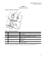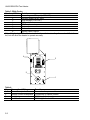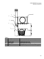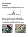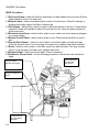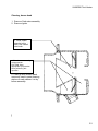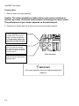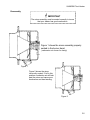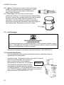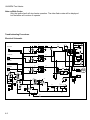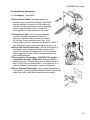
1
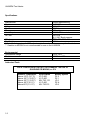
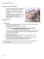
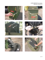
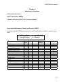
REV 14MAY02
PN 168324
Heater, Tent
Model UH68ODK, UH68ODH
Manual for UH68G1 with
Hunter Part Number 53100
Outdoor Kit Installed and
UH68ODH, Part Number 168325
Hunter Manufacturing Company
30525 Aurora Rd
Solon, OH, 44139
www.huntermfgco.com
WARNING!
FUEL WARNING
Gasoline and JP-4 should NOT be used with the UH68OKD/ODH under any
circumstance. Only JP-8 or an approved alternate fuel as detailed in Chapter 1.
Failure to observe fuel requirements could cause damage to the heater assembly
and injury or death to personnel within or around the tent and the heater
assembly. Always place fuel can in well-ventilated area as far away from open
flames and other potential ignition sources as possible. Fuel spills shall be
cleaned up in accordance with local requirements.
Always switch heater to the OFF position and wait until the vent fan is off before
refueling.
EXPLOSION HAZARD
FUEL LEAKS
Do not operate heater if fuel leak is detected.
DEATH OR SERIOUS INJURY
CARBON MONOXIDE
Carbon monoxide is without color or smell, but can kill you. Breathing carbon
monoxide produces symptoms of headache, dizziness, loss of muscular control,
a sleepy feeling, and coma. Brain damage or death can result from heavy
exposure. Carbon monoxide occurs in the exhaust fumes of fuel-burning heaters
and internal combustion engines. Carbon monoxide can become dangerously
concentrated under conditions of no ventilation.
Precautions must be followed to ensure operator’s safety when the Space
Heater, Convective is in operation.
• DO NOT operate Heater in an enclosed area without proper ventilation.
• BE ALERT at all times during operating procedures for carbon monoxide
poisoning. If symptoms are present, IMMEDIATELY evacuate personnel
to fresh air.
• BE AWARE the field protection mask used for nuclear-biologicalchemical attack WILL NOT protect you from carbon monoxide
poisoning.
THE BEST DEFENSE AGAINST CARBON MONOXIDE POISONING IS GOOD
VENTILATION.
ELECTRIC SHOCK
Always disconnect power cable from heater before doing any type of service
work or repairs.
SEVERE BURNS
HOT EXHAUST
DO NOT MOVE THE HEATER ASSEMBLY WHILE ANY OF THE ADVISORY
LIGHTS ARE LIT.
Small, portable, shelter heaters of this type are not designed to be moved during
operation or before purge cycles are complete. Serious injury, burns, or death
can occur if the heater assembly is moved while operating, the HEAT LED is on,
or the vent fan is still running.
During operation, some metal components of the heater assembly, such as the
outlet duct, the Pop Up Duct Adapter, combustion exhaust pipe, etc., can cause
severe burn injuries if contact with bare skin occurs.
During heater operation, air leaving the HEATED AIR OUTLET of the heater and
passing through outlet duct may exceed 220°F. Make sure tent personnel are
aware of burn hazards and equipment hazards presented by the heated air.
Combustible material must be kept at least 2 feet away from the sides of the
heater during operation.
Do not attempt service procedures on a burner that has recently been in
operation. Let the burner cool down before performing these procedures to avoid
the possibility of serious burns. Never touch the exhaust stack while heater is
operating. Surface temperatures can exceed 800 degrees F. Allow sufficient time
for heater to cool before removing exhaust stack. The exhaust elbow will remain
hot for several minutes after the heater has shut down.
UH68ODK Tent Heater
Chapter 1
Introduction
Scope
Type of manual:
Operators
Model and Name:
UH68ODK and UH68ODH, Forced air tent heater, with ducts.
Purpose of Equipment: Circulates heated air in the Alaska, TEMPER tent, and other soft
walled structures. Maintains temperature via room thermostat in the remote control
panel. Control panel also has diagnostic and operating LED’s.
General
The UH68ODK is Hunter model UH68G1modified for outdoor usage. The outdoor kit
may be field installed or factory installed. The UH68ODK burns all grades of diesel fuel
and JP8 to generate heated air. Fuel is pumped from remote tank to the carburetor,
drawn through the fuel jet by venturi action of the mixer nozzle, ignited, and burned in
the heat exchanger. A fan, capable of delivering up to 2 IWC static pressure, blows the
heated air into the tent. The UH68ODK has the following applications:
•
•
Alaska tent, Temper Tent
Medium and small soft wall shelters
Features
•
•
•
•
•
Variable room temperature control
Remote control with 20 foot cable
Diagnostic LED’s on remote control
Low voltage opto-isolated controls to eliminate shock hazard.
“Fan only” ventilation.
WARNING!
ELECTRICAL SHOCK
Attempting to use an unmodified UH68 series heater outdoors
may result in electrical shock, injury or death
1-1
UH68ODK Tent Heater
Specifications
Manufacturer
Model
Voltage
Cycles
Power
Heat Output
Air Flow
Hunter Manufacturing
UH68ODK
120 VAC
50-60Hz
400 watts
60,000 BTU nominal
650 CFM
@ .5 IWC Back pressure
**Fuel
*DF2, DF1, DFA, JP8
Dry Weight
130 Lbs.
* Heater is factory set on for DF2, adjustment to the carburetor is necessary for other fuels.
** Gasoline or MOGAS is not recommended for use on the UH68ODK
Environmental
Temperature Range
Elevation
-65 to 120 F
10,000 feet MSL
Authorized Fuels
NOTE: HUNTER MFG DOES NOT RECOMMEND THE USE OF
GASOLINE OR MOGAS, or JP4
Ambient Temperature
Above +20°F (-6,7°C)
Above -25°F (-33.3°C)
Above -25°F (-33.3°C)
Above -60°F(-51.l°C)
Above-60°F(-51.1°C)
1-2
Specification
VV-F-800
VV-F-800
MIL-T-83 133
VV-F-800
MIL-T-83133
Military Symbol
DF-2
DF-1
JP-5
DF-A
JP-8
UH68 ODK/ODH Tent Heater
Operators Instructions
Chapter 2
Operating Instructions
Operator Controls and Indicators
2
1
3
4
6
5
Table 2. Controls and Indicators
Key
Control or Indicator
1
Main Switch
2
3
4
Room Thermo
Main Power LED (green)
Standby LED (green)
5
Heat LED (green)
6
Fault LED (red)
Function
Starts and stops heater. FAN position turns fan only on
for ventilation
Set for desired temperature. *
Indicates heater is plugged in to AC power
Indicates main switch is ON but room thermo is not
calling for heat
Indicates main switch is ON and combustion system is
energized
Blinks a diagnostic code for corresponding fault. (see
fault codes table 3)
* Heat output is constant. Raising room thermo setting does not heat shelter faster.
2-1
UH68 ODK/ODH Tent Heater
Table 3. Blink Codes
Number of Blinks Problem
1
Low voltage at AC input (< 100 VAC)
2
Reverse polarity at AC input
3
High voltage (>130 VAC)
4
Not used
5
PC Board over temp
6
Not used
7
Not used
8
Ignition Fault Lockout
Note: Only the Ignition fault lockout will shut down the heater. Any other code will flash the red
led, but still allow the heater to operate normally.
4
3
2
1
Table 4.
Key
Connection / Fitting
1
Power Receptacle
2
Remote Control Receptacle
3
Fuel Inlet
4
Fuel Overflow
2-2
Function
Connection for power cable
Connection for remote control
QD fitting for fuel supply
QD fitting for fuel overflow
UH68 ODK/ODH Tent Heater
Operators Instructions
5
6
4
3
2
1
Table 5.
Key
Description
1
Inlet Adapter
2
Storage compartment
3
Exhaust elbow
4
Stack support
5
Exhaust stack
6
PUDA
Function
Attachment point for return air duct
Storage for stack, fuel lines, power cord etc.
Exhaust stack rests on top
Holds exhaust stack securely
Double wall exhaust stack for extra safety
Pop Up Duct Adapter, attachment point for supply duct
2-3
UH68 ODK/ODH Tent Heater
Operation Under Usual Conditions
Setup
Alaska Tent TEMPER Tent
Completely setup the Alaska tent, and deploy the duct collars at the end in which you are to
setup the heater. Make sure the generator or power supply is on line.
Before setting up the tent and heater, some thought should be given to the orientation of the
structures as to the prevailing wind direction. Try to orient the heater and shelter so the
exhaust is blown down range away from doors and shelter openings.
CAUTION
TWO PERSON LIFT
The UH68ODK weighs 130 Lbs. Attempting to lift
without proper personnel may cause serious injury
1. Move the UH68 ODK into position near the duct collars. Set up off ground using skid or
similar.
2. Open PUDA (1) and remove remote control(2) power cord(3) and inlet adapter(4).
3. Attach inlet adapter(4) to heater and attach return duct(5) using band clamp(6). Pay special
attention to airflow tag(7) on duct. DO NOT PUT RETURN DUCT ON BACKWARDS. This
will restrict incoming airflow.
4. Deploy PUDA(1) by tilting upwards and putting pins(8) in supports(9).
5. Attach supply duct(10) using band clamp(6). Pay special attention to airflow tag(7).
6. Pull ducts into tent and point heated air duct away from inlet duct, towards center of tent.
Pull heater away from tent until ducts are straight but not taught (12).
1
3
2
4
2-4
UH68 ODK/ODH Tent Heater
Operators Instructions
4
4
6
5
7
8
9
10
6
Return
7
Supply
12
2-5
UH68 ODK/ODH Tent Heater
7. Uncoil remote control (2) inside tent and feed through the collar with the return duct(5).
Attach remote control (2) to heater. Make main sure switch is in the off position.
8. Attach power cable (3) to heater then plug in to power supply. The green, main power LED,
on the remote panel should illuminate.
9. Check fuel in can(14), fill if necessary with authorized fuel (see section one). Attach Suction
Feed Adapter(15) and open vent(16).
10. Attach fuel supply line(17) to Suction Feed Adapter(15). Make sure drain cock(18) on
supply line(17) is closed. Attach supply line(17) to heater QD fitting(19). Move the fuel
can(14) as far away from the heater as possible without pulling the fuel supply line(17)
taught.
11. Attach overflow line(20)
NOTE!
Open end of overflow hose should discharge to a safe, outside location along a
downslope and below the level of the heater. A piece of commercial petroleum
absorbent material (21), will be placed under the end of the overflow hose to catch any
fuel that may spill.
12. Attach exhaust stack cap(22) to stack(23). Slide exhaust stack(22) through stack holder(24)
on side of PUDA and over exhaust elbow. Push down on stack holder(24) to stabilize stack.
2
2-6
3
UH68 ODK/ODH Tent Heater
Operators Instructions
16
19
18
17
15
14
MAX DISTANCE
17
14
22
23
20
24
21
2-7
UH68 ODK/ODH Tent Heater
Operating Procedures
The UH68 ODK can be operated in either of two modes:
a. Heating mode.
b. Fan only mode.
Heating Mode
!
CAUTION
Never operate the UH68 ODK with the pop up duct
adapter closed. Damage to the internal parts may
occur.
1. Set the room thermo (1) to the lowest
detent setting.
2. Move main switch (2) to HEAT. The
green standby LED (3) should
illuminate
3. Rotate the room thermo until the green
HEAT LED (4) illuminates.
1
After a five second delay the burner will
come on. You may not hear the burner if
you are inside the tent or there is a lot of
ambient noise. The vent fan will come on
when the heat exchanger comes up to
3
temperature. The amount of time will vary
(30 to 120 seconds) depending on the
4
ambient temperature. Once the vent fan
comes on the heater will continue to
operate until the call for heat from the room thermo is satisfied or the main switch is
turned off. If the airflow is reduced due to very high back pressure, the burner will cycle
off from time to time.
4. Adjust room thermo (1) as necessary.
Fan Mode
Use this mode when no heat is required.
1. move main switch (2) to FAN position.
The vent motor will start and ambient air will circulate through the shelter
2-8
2
UH68 ODK/ODH Tent Heater
Operators Instructions
Shutdown
!
CAUTION
Never disconnect power to the heater while heat exchanger is
hot. Damage to the internal parts may occur.
1. Place main switch in off position.
Vent fan will continue to run until heat exchanger has cooled down. The length of time
will vary depending on ambient temperature.
Operation Under Unusual Conditions
Extreme Cold, Below 10oF
There is a thermostatically controlled fuel heater in the carburetor block. This heats the fuel
when the temperature drops below 40 degrees F. Preheating the fuel aids combustion ignition
during extremely cold conditions. Take these steps to insure reliable operation during extreme
cold:
1. Keep fuel can full to prevent condensation in tank.
2. Clean snow and ice from fuel can filler to prevent moisture from entering fuel can,
causing fuel line freeze up.
3. Rotate the room thermo fully counter clockwise to the lowest detent setting. Turn
main switch to heat. Allow heater to stand for about sixty seconds. This allows the
carb heater to reach operating temperature before heater is started. Operate as
described in HEAT MODE section.
Operation at High Altitudes
The UH68 ODK is designed to operate at elevation up to 10,000 feet without any
modifications. At 10,000 feet heat out put may be reduce about 15 percent. This is a
normal condition which cannot be prevented.
2-9
UH68 ODK/ODH Tent Heater
Operation Under Rainy Conditions
1. The remote control panel is water-resistant. No
special instructions for setting up in the rain.
2. Do not remove protective covers from the
remote and power receptacles until ready to
connect.
3. To keep rain water from collecting around
heater, place heater on skid (1), bricks or small
logs. Make sure heater is stable.
4. Paint all chipped and scratched surfaces to
prevent rust
1
Strike Procedure
1. Drain fuel lines
1. While heater is burning, open drain cock (1) on fuel supply line. Let heater run until
you hear combustion stop. (burner)
2. Move main switch to OFF and allow heater to cool.
BEFORE PROCEDING MAKE SURE HEATER IS COOLED DOWN AND
DISCONNECTED FROM POWER SUPPLY
3. Close drain cock (1) on supply line. Using a rag or fuel absorbent mat remove supply
line from heater at QD fitting. Make sure to hold rag beneath heater QD fitting to
catch any fuel left in the fitting.
4. Attach heater QD cover (2).
5. Hold supply line (3) above fuel can and open drain cock (1). Raise as high as
possible to let fuel drain into fuel can.
6. Close drain cock (1) and detach supply line from suction feed adapter. Coil up
supply line and connect both ends together (4) to keep out dirt.
7. Disconnect overflow line and coil up. Attach QD cover (2)
2. Disconnect ducts (6) and clamps (5), store separate from the heater.(* see duffle bag
option for storage)
3. Remove stack, fold PUDA fabric (7) and close PUDA leaving doors open.
2-10
UH68 ODK/ODH Tent Heater
Operators Instructions
1
2
2
1
4
3
5
7
6
5
6
2-11
UH68 ODK/ODH Tent Heater
4. Remove inlet duct collar (8) and stow in PUDA
5. Disconnect Remote Cable (9) coil up and stow in PUDA
6. Disconnect power cable (10), coil up and stow in PUDA. Close PUDA
7. Remove stack (11) and stow in storage compartment (13). Secure with spring hold
down (12).*
8. Store fuel lines in storage compartment (13)
9. Fuel can adapter may be left on the fuel can. Make sure to close the air vent (17).
Heater can now be transported.
*Packing using duffle bag
1. collapse both ducts (14) together.
2. place band clamps (15) over collapsed ducts
3. place stack (11) inside ducts
4. place all inside duffle bag (16)
5. Fuel can adapter may be left on the fuel can. Make sure to close the air vent (17).
2-12
UH68 ODK/ODH Tent Heater
Operators Instructions
9
10
8
11
11
14
15
12
13
16
14
14
11
16
17
2-13
UH68ODK Tent Heater
Chapter 3
Maintenance Instructions
Lubrication Instructions
Doors, Pop Up Duct Adapter
Lubricate all hinges with MIL-A-907 anti-seize compound.
Preventative Maintenance Checks and Services (PMCS)
Systematic, periodic PMCS are essential to ensure that the heater is ready for operation at all
times.
B – Before Operation
D – During Operation
Description
Fuel Line system
Exhaust Stack
Fuel Supply
Electrical Connections
Remote Control Panel
PUDA
Ducts
Sediment Bowl
Carburetor
Burner Head
Igniter
Fuel Pump
Heat Exchanger
Overheat Safety System
A – After operation
Q – Quarterly
Ref. Daily Monthly
Para.
1.1
1.2
1.3
X
1.4
1.5
1.6
1.7
1.8
1.9
1.9
1.10
1.11
1.12
1.13
Semi
Annually
Annually
Interval
BDA
B
BD,9Hrs
B
B
B
B
1000 Hrs
500 Hrs
X
X
X
X
B
3-1
UH68ODK Tent Heater
PMCS Procedures
1.1 Fuel Line System - check all fuel lines and fittings for leaks. Make sure vent at top Suction
Feed Adapter is clear of ice and snow.
1.2 Exhaust stack - make sure exhaust stack is clear of ice and snow. Check for damage or
anything that might obstruct the flow of exhaust gas.
1.3 Fuel Supply – before filling, check for water or dirt at the bottom of the can. Fill can before
operation. Heater will operate for about 9 hours with full can. Check at regular intervals to
avoid running dry.
1.4 Electrical connections - check cord for nicks or cuts, make sure cord is securely plugged
in to power supply
1.5 Remote Control Panel – check cord for nicks or cuts. Check overall condition of control
box
1.6 Pop Up Duct Adapter – check for cuts in fabric. In the field, repair cuts with duct tape.
Cuts may be sewn shut. If cut is too large to be sewn shut, replace entire fabric interface.
1.7 Ducts - check for cuts in fabric. In the field, repair cuts with duct tape. Cuts may be sewn
shut. If cut is too large to be sewn shut, replace entire duct.
1.8 Sediment Bowl – check for dirt and water. Clean if necessary.
1.9 Carburetor, Burner Head – use the following procedure to service the carb and burner
head:
Look for carbon
deposits in this area.
Check for carbon on
igniter.
Check mixer for
dirt and carbon
deposits
3-2
Check carb bowl
for water, dirt,
and varnish
UH68ODK Tent Heater
Cleaning, burner head
1. Remove Carb mixer assembly
2. Remove Igniter
3. Clean carbon
deposits in this
area. Use a small
wire brush.
4. Clean these areas using
compressed air.
CAUTION: Wear
appropriate eye protection
when performing this
operation
5. Finish up with solvent wash
commonly used in parts cleaning
stations or carb cleaner. Let dry
before assembly.
]
3-3
UH68ODK Tent Heater
Cleaning, Mixer
1. Remove mixer from carb assembly
Caution: The mixer assembly is made of brass and can be scratched or
dented very easily. Great care must be taken not damage the mixer nozzle.
The performance of your heater depends on this delicate part.
2. Soak mixer in solvent bath for an hour or so to loosen up carbon deposits.
3. With a flashlight look for dirt
or carbon here. Dirt may be
blown out using compressed
air. Do not use a pick or any
hard tools to clean this area
There are two concentric rings
here. The center ring is paperthin. Inspect for dents, scratches
and nicks. This area must be free
of dirt and carbon.
Mixer Assembly
4. Clean this area using a soft
cloth and solvent. Wipe with a
twisting motion.
*
IMPORTANT
If the mixer assembly cannot be cleaned satisfactorily,
replace it.
3-4
UH68ODK Tent Heater
Reassembly
*
IMPORTANT
The mixer assembly must be seated correctly to insure
that your heater has good combustion.
Figure 1 shows the mixer assembly properly
seated in the burner head.
( carburetor not shown for clarity)
Figure 1
Figure 2 shows the mixer
incorrectly seated. If left in this
position combustion air will leak
past the mixer and cause poor
combustion and hard starting.
Figure 2
3-5
UH68ODK Tent Heater
1.10 Igniter – Check igniter for carbon build up and signs
of wear. As the igniter wears the gap between 1. and 2.
will become wider and oval shaped. Replace when
signs of wear are evident.
1.11 Fuel Pump – the fuel pump has a filter screen
located at the inlet end. To clean remove three screws holding
the cap on, remove the cap being careful not to tear the gasket,
and remove the filter screen. Pay close attention to the
orientation or the filter screen in the pump foe reassembly.
Clean screen and cap with carb cleaner. Cap has a magnet to
trap metal particles. Reassemble and check for leaks.
Filter located
here
1.12
Heat Exchanger
WARNING!
DEATH OR SERIOUS INJURY
CARBON MONOXIDE
The heat exchanger must be inspected annually, or more frequently if heater usage is
heavy. A damaged heat exchanger can allow poisonous gases to seep into the heated
enclosure causing illness or death to occupants.
Inspect heat exchanger in accordance with the procedures in TM 5-4520-253-13
1.13 Overheat Safety System
The overheat safety switch must be cycled before heater is used after storage or
replacement of overheat switch.
Overheat Testing - Start heater and let run for about 10 minutes
without the ducts attached. Using a piece of
paper or similar, block the inlet air about
Block inlet air
three-quarters of the way shut. At 70 degrees
here for testing
F the heater will shutdown in about a minute.
Temperature at shutdown should be between
275 and 300 degrees F. If the overheat safety switch does not
work it MUST be replaced. Replace thermostat in accordance
with procedures in TM 5-4520-253-13, 3-105
3-6
UH68ODK Tent Heater
3-7
UH68ODK Tent Heater
Chapter 4
Troubleshooting
General
This section contains information for locating and correcting most operating problems. This
manual can not list all that may occur. When performing trouble shooting procedures, follow
all warnings and safety procedures. At no time does this manual supercede good common
sense.
Sequence of Operation
1. Move main switch to HEAT. The green standby LED should illuminate
2. Rotate the room thermo to the nine o'clock position or until the green HEAT LED
illuminates.
3. After a five second delay the burner system will come on. This includes the ignition
transformer, fuel pump, fuel solenoid, and combustion blower.
4. The vent fan will come on when the heat exchanger comes up to temperature and
the flame switch closes. The amount of time will vary (30 to 120 seconds) depending
on the ambient temperature.
5. Once the vent fan comes on the heater will continue to operate until the call for heat
from the room thermo is satisfied or the main switch is turned off. If the airflow is
reduced due to very high back pressure, the burner will cycle off from time to time.
This is normal.
Blink Code Troubleshooting
Blinks
Para. Problem / Remedy
Low voltage at AC input (< 100 VAC)
1
2
3
4
5
6
7
8
1.1
1.2
1.3
1.4
1.5
1.6
Check power supply or generator. If using an extension cord, make sure the wire is
heavy enough.
Reverse polarity at AC input
Check power supply or generator. If using an extension cord check connections.
High voltage (>130 VAC)
Check power supply or generator
Not used
PC Board over temp
Not used
Not used
Ignition Fault Lockout
Check fuel supply, refill if necessary.
Check Flame switch.
Check fuel pump
Check fuel flow at carburetor
Check Ignition transformer
Check Overheat thermo
4-1
UH68ODK Tent Heater
Note on Blink Codes
Only the ignition fault will stop heater operation. The other flash codes will be displayed
but the heater will continue to operate.
Troubleshooting Procedures
Electrical Schematic
0.1uF
U5
R10
6
1
180
VENT FAN
M2
R8
38
J6
1
2
180
U8
5
G
4
M1
CONN-H2
0.01uF
1
2
3
4
5
6
3
MOC3031
1K
CARB HTR
6
1
U7
5
2
G
4
180
J5
M2
R6
1
2
38
1
2
3
4
5
6
SW-SP-ON-OFF-ON
D9
R19
150
CONN-H6
CONN-H6
U4
R11
LED
SW1
J10 J12
D8
R9
D12
0.1uF
1N4001
2
ZCC
R21
150
1N4001
C8
C12
C11
D7
R15
LED
J13
R14
1
2
3
4
180
CONN-H4
CONN-H2
M1
C9
0.01uF
IGNITION
J4
R7
ZCC
3
D11
R20
150
U6
R12
COMB BLR
6
1
5
2
180
J3
M2
R3
1
2
38
180
U9
G
M1
C10
0.01uF
TR1
24 V @ 1.5A
AC1
BR1
S1
C7
J11 J15
5
ZCC
3
1
2
3
MOC3031
4
1K
1
1
2
U3
V+
GND
GP5/OSC1/CLK
GP0/AN0
GP4/OSC2/AN3 GP1/AN1/Vref
GP3/MCLR GP2/T0CLK/AN2/I
PIC12C67X
1
2
8
CONN-H2
CONN-H2
7
6
FLAME SWITCH
N.O. 125F (i.e. it closes at 125F)
5
+
AC2
-
4
R5
6
R17
R23
10K
10K
1
2
3
4
7
4
TR2
1
C1
D3
MOV
MOV
6
1
2
FUEL PUMP
J2
4
OVERHEAT SW
FUEL SOL.
AC1
+
8
U1
BRIDGE
1.5 A 100V
8V @ 300mA
R16
D2
1
5.0
MOV
J7
1
2
-
7
J14
J1
C2
1
2
3
CONN-H3
J8
J9
C5
100uF
Cir.Brk1Cir.Brk2
R2
500K
R1
R4
20K
500K
D13
1N4004
D6
TVS-18V
C6
0.1uF
L4805
MOUSER # 511-L4805CV
3
VI
VO
C4
100uF
R18
5.6K
22uF
22uF
330uF 63WV
1
2
C3
4.7V
GND
D1
D5
BR2
5
2
8
TVS
AC2
D4
LED
R13
0.1uF
CONN-H2
4-2
LED
1K
1
2
CONN-H2
BRIDGE
4 A 600V
D10
R22
150
MOC3031
U2
nc
V+
Vnc
TMP17
nc
nc
nc
nc
8
7
6
5
UH68ODK Tent Heater
Troubleshooting Procedures
1.1 Fuel Supply – See PMCS
1.2 Check Flame Switch – the flame switch is a
normally open heat sensitive switch. The UH68G
has two switches. As used in the 68 outdoor kit,
only the normally open switch is active. Normally
switch 1, red and brown wires, is used. The
other switch is normally open and is not used.
1.3 Check Fuel Pump – The fuel pump operates
on 24vdc. Energize the pump and listen for
operation. Remove outlet connector and check
for fuel flow. Pump develops about 4 psi., if fuel
slowly runs from pump, clean filter as defined in PMCS. If
fuel runs out of pump at a good steady rate pump is ok.
1.4 Check Fuel Flow at Carburetor – remove fuel needle (1),
start heater. when combustion blower comes on fuel
should run from the fuel needle hole. If not fuel flow has
been stopped up stream. Check fuel solenoid and float
bowl needle and seat.
1.5 Check Ignition Transformer – CAUTION! The ignition
transformer develops 10,000 volts. Disconect ignition
cable form igniter. Position spring at tip of cable not more
than 1/8 inch from grounded surface. Turn heater on. If no
spark is detected, check power to igniton transformer.
1.6 Check Overheat Thermostat – the overheat thermostat (1)
is a normally closed temperature sensitive switch. Disconnect
wires from switch, and check continuity across switch.
4-3