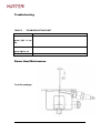
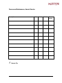
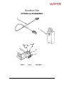
1
 ! " #$ ! "
%%%&'
Propane Heater
20,000 BTU/HR Model PH20-30A
With Automatic Gas Ignition Control
Installation Operation Service
EXHAUST GASES
Do not operate heater in an enclosed area unless the exhaust
gases are piped outside. Exhaust gases may contain carbon
monoxide, a colorless and poisonous gas.
FUEL USE
This heater is designed for use with propane (LP gas) only. Do not
attempt to use gasoline as fuel since fire or explosions may result.
Use this heater only with gas regulator part number 88301-T
supplied with the heater. Operation with other regulators voids all
warranties and may result in fire, explosion, or damage to the
heater.
ELECTRICAL
Heater must be grounded through ground screw supplied. Do not
use the fuel line as an electrical conductor or ground connections.
Use of the fuel line as electrical or ground conductor may result in
fire or explosion. Before performing maintenance or inspection
(except operating tests), disconnect the power source. Do not
operate the heater with the covers off. The tilt switch is a safety
device that stops heater operation in case the vehicle overturns.
Do not remove this switch or defeat its purpose.
Do not operate the heater at less than 11volts. Propane flow to the
burner head is constant, but blower motor speed and combustion
airflow vary directly with voltage. Operation on low voltage will
produce poor burning, smoke, and unburned fuel mixtures.
Section One____________________________________________________________ 3
Introduction and Description __________________________________________________ 3
Description _______________________________________________________________________ 3
Section Two ___________________________________________________________ 4
INSTALLATION INSTRUCTIONS ____________________________________________ 4
Pre-Installation Inspection____________________________________________________________ 4
Location and Mounting ______________________________________________________________ 4
Electrical Requirements (FIG.1) _______________________________________________________ 6
Fuel Requirements (FIG.2) ___________________________________________________________ 6
Exhaust and Combustion Air Requirements (FIG.3)________________________________________ 7
Heater Mounting Dimensions (FIG.6)___________________________________________________ 8
Fuel Connections ___________________________________________________________________ 9
Electrical Connections______________________________________________________________ 10
Section Three _________________________________________________________ 12
OPERATION ______________________________________________________________ 12
Controls and Indicators _____________________________________________________________ 12
Theory of Operation _______________________________________________________________ 13
Starting _________________________________________________________________________ 14
Section Four __________________________________________________________ 15
This manual contains installation, operation, maintenance, and repair instructions
for Model PH-20-30A Heaters manufactured by Hunter Manufacturing Company, Solon,
Ohio.
The Falconaire PH20-30A is a 12 VDC Microprocessor Based, Direct Spark
Ignition, thermostatically controlled heater. The control utilizes a microprocessor to
continually and safely, monitor, analyze and control the proper operation of the gas
burner. Value added features such as, combustion blower control, LED diagnostic
output, automatic one hour reset, and multiple ignition tries, highlight the controls
benefits.
Model PH-20-30A is designed for use solely with propane (LP gas) as fuel.
Combustion air is supplied by a single-stage combustion air blower, and fuel flow to the
burner head is controlled by a solenoid valve and a restrictor in the fuel line. Because
the propane enters the burner head as a gas, no carburetor is required. Ignition of the
propane is accomplished with a spark plug-like igniter, which is supplied with high
voltage current from the Electronic Control Module (ECM).
Heater case dimensions . . . . . . . . . . . . . . . . . . . . . 16 in. long x 11 in. wide x 6 3/4 in. high
Weight . . . . . . . . . . . . . . . . . . . . . . . . . . . . . . . . . . . . . . . . . . . . . . . . . . . . . . . . . . … 28 lbs.
Shipping weight . . . . . . . . . . . . . . . . . . . . . . . . . . . . . . . . . . . . . . . . . . . . . . . . . . . . . 30 lbs.
Rating . . . . . . . . . . . . . . . . . . . . . . . . . . . . . . . . . . . . . . . . . . . . . . . . . . . . . . . . 20,000 BTU
Heated air outlet diameter . . . . . . . . . . . . . . . . . . . . . . . . . . . . . . . . . . . . . . . . . . . . . . . 5 in.
Exhaust outlet . . . . . . . . . . . . . . . . . . . . . . . . . . . . . . . . . . . . . 1 1/4NPT stainless steel pipe
Combustion air inlet . . . . . . . . . . . . . . . . . . . . . . . . . . . . . . . . . . . . . . . . . . . . .1 in. OD tube
Fuel connection . . . . . . . . . . . . . . . . . . . . . . . . . . . . 5/8-18 UNF x 45 deg flare male fitting
Electrical requirements . . . . . . . . . . . . . . . . . . . . . . . . . . . . . . . . . . . . . . . . . . . . 12 volts DC
Current draw (average, start and run) . . . . . . . . . . . . . . . . . . . . . . . . . . . . . . . . . . . .8 amps
Fuel requirement . . . . . . . . . . . . . . . . . . . . . . . . . . . . . . . . . . . . . . . . . . . . Propane (LP gas)
Fuel consumption . . . . . . . . . . . . . . . . . . . . . . . . . .1 hour/pound on high thermostat setting
Burner . . . . . . . . . . . . . . . . . . . . . . . . . . . . . . . . . . . . . . . . . . . . . . . . . . . Low pressure type
Ignition . . . . . . . . . . . . . . . . . . . . . . . . . . . . . . . . . . . . . . . . . . . . . . . Electronic ignition pack
NOTE
All specifications are based on the use of a vapor-withdrawal gas
bottle and gas regulator part number 88301-T. Operation under
other fuel conditions voids all warranties. This regulator provides the
mandatory pressure (11 inches H2O) required by the calibrated
burner head orifice.
1. Inspect the heater for damage that may have occurred
during shipment. Check against the packing list or
invoice for lost parts.
2. Inspect the controls for loose or missing hardware.
Read all warning
tags supplied
with the heater.
Perform all duties
indicated on the
tags.
3. Inspect all lines, tubing, and fittings to see that they are
secure and free of breaks, kinks, or other damage.
NOTE
A warranty card is packed with each heater leaving the factory. Attached
is a return postal card. It is the duty of the dealer to ensure that both the
owner's copy and the registration card are completed and the registration
card returned to Hunter Manufacturing Company. To be certain that you
obtain the benefits of the above warranty, this card should be returned
within 10 days from the date you purchased this equipment
!
"
.
CAUTION
The heater is designed for use in the horizontal position with the heat exchanger
exhaust outlet down. Other permissible positions are those which retain the
motor shaft in the horizontal plane. Operation in any other attitude voids all
warranties and may result in damage or rapid heater wear unless modified for
such use by Hunter Manufacturing Co
The heater is normally installed within the compartment being heated. It can be
installed outside the compartment being heated by using a flexible heat duct to direct the
heated air into the compartment.
The heater must be shielded against direct contact from rain and snow.
The tilt switch is a safety device that stops heater operation in case the
vehicle overturns. Do not remove this switch or defeat its purpose.
LOCATION AND MOUNTING (cont.)
1. Mount the heater horizontally, as shown in figure 4. Choose a mounting
location that will enable mounting the heater on a level surface, with adequate room
around the heater for removal and service. Check that the tilt switch is upright. Refer to
figure 6 for mounting dimensions and clearances.
2. After selecting a location, remove all combustible material from area, within
two inches of where the heater will be located. This includes carpeting, rubber mats,
plywood flooring, etc.
3. Cut holes as required for air inlet and exhaust. Remove cross bar and covers.
Set heater in place over inlet and exhaust holes and mark mounting holes. Remove
heater and drill 5/16 inch diameter holes for mounting studs (page 8)
CAUTION
Use heat shield and exhaust collar as described below to prevent damage to
paint and furnishings of vehicle from excessive heat.
4. Position heat shield ( page 17) around the hole for the exhaust connection, as
shown in figure 3. The heater case becomes hot in this area during operation, and the
heat shield is required to protect the vehicle from excessive heat. Set the heater over the
mounting holes and secure with mounting studs using the nuts and lock washers
supplied with the heater.
.
Exhaust gas must be piped to the outside of the heated compartment. Do not
allow the exhaust gas to exit directly beneath the vehicle
5. Direct the exhaust away from the compartment using elbow and nipple , and
additional 11/4-inch nipples as required. If the exhaust must pass through an additional
vehicle body panel or floor, use exhaust collar to protect paint and/or trim. Cut a hole in
the panel 2-7/8 to 3 inches in diameter to ensure adequate clearance between the hot
pipe and the painted panel and to provide access for later servicing. Cover the opening
with exhaust collar and direct the exhaust pipe through it.
6. If the heater is mounted entirely within the cab, connect a 1-inch rubber or
plastic hose to the air inlet and run it outside the cab to provide fresh air for combustion.
#
( ) *
(+,
) %--
-&) %- -
. )//0
1 )
! .
+ 2 34,5 26
626+ 7 82462
628 7462
(6627. ,
,,8
' ,
%- -
1-& ') *
/' '
-) )- +9
*&: 0) -
$%
4 ,&
4-;- / .)
8) 1/ : 0
8) !!
)//-
%- 3 '
/- 0
-< '-
%- &) ))
- 11
4- /)) ) * -&) % &' %-
-
# --
!= -
$%
#
- -)) : )
>) /&) /-&: / *0 )
- -:)
6>) &
))0 @)//-A
(-& *0 /
- >-* &
'>-''
2
-& >) % - &) % 7
/-/ ) /? -
!- - %)
/-
+& &'*)-
- -: )- / +2
-)
>-'' ? *) &'
%
$%
' &*
% 8) )/&)
1- /-&-
& &*
6>) -/
%0) /-& %
/) ,)
,'*)- - 7:
+& - ' )-
2 ' - -) /)--
-/ 1 )%-& ) -) /
#
,-&- #)
@) )//-A
(+, %
)//0
# /- (,
@) )//-A
' 2')
@/-A
/ 3
8) &-&- ) /) - *' *0 D- ) /& *' '0 * )
-/ 6>) -
BC ' &: *0 )- :
) *0 -) /
)-
)*")+
. )&%
/1- 8) & )&
&))-) + )
- ) &-& && + 0 '- %
&-& 2 (76D
# 7
# --
,1 '1 &&
E 7
(!
"%
: This heater is designed for use with propane (LP gas) only. Do not
attempt to use gasoline as fuel since fire or explosion may result. Use this heater
only with gas regulator part number 88301-T and POL connector part number
88014 supplied with the heater. Operation with other regulators, or tampering
with the regulator adjustment, voids all warranties, and may result in fire,
explosion or damage to the heater.
1. Locate and mount the propane tank (gas bottle) away from the engine and
heater exhaust ports. The location should also protect the tank from accidental
mechanical damage.
CAUTION
Use only propane tanks which are designed or modified for vapor withdrawal.
Connect the heater to the VAPOR port on the tank. Damage to the heater and
regulator will result if connections are not made properly.
2. The propane tank must be a gas bottle designed or modified for vapor takeoff
only. Install POL (put on left) connector (fig.2) at the IN port on regulator, and install
these assembled parts into the propane tank shutoff valve, as shown in figure 2.
NOTE: POL connector, part number 88014, incorporates an
excess flow valve. Use of an excess flow valve is a safety
requirement of the Department of Transportation (DOT).
3. Fuel line from the regulator to the heater should be 3/8-inch diameter tube. If
available, a short piece of flexible fuel line may be used at the regulator to make bottle
changing more convenient. Flexible line must be approved 300-psi test neoprene hose,
which can normally be obtained from the propane supplier.
CAUTION
Use of flexible fuel line is recommended. If rigid line is used, it
must withstand vehicle vibration, which may cause rigid line to crack.
Ground the heater electrically through the ground screw provided
on the heater case, and connect to a clean, secure chassis ground. Do not use
the fuel line as a ground or electrical conductor. Use of the fuel line as an
electrical or ground conductor can result in fire or explosion. Do not rely on
heater mounting studs to provide electrical ground.
1. Refer to the wiring diagram in figure 7, locate the power and ground
connections on your heater. The ground terminal is located one inch to the left of the fuel
inlet. Connect this terminal to a good, clean chassis ground, using the wire size listed in
Table 1.
2. Refer to the wiring diagram and connect the red power lead from the heater
fuse to the vehicle electrical system, using the wire size specified in Table 1. This line
should be hot at all times, so the heater can purge even if the vehicle ignition is off.
Protect the vehicle with a circuit breaker or 10 amp fuse in the feed line.
Less Than 10
10 gauge
10 to 30
8 gauge
Over 30
6 gauge
Table 1. Wire Sizes
! "
(figure 7)
Symbol
B1
ECM
E1
L1
LED1
PS1
S1
S2
S3
S4
SW1
TB
Description
Blower Motor
Electronic Control Module
Igniter
Solenoid Valve
L.E.D. Assembly
Pressure Switch
Tilt Switch
Overheat Thermostat
Room Thermostat (optional)
Comfort Control Thermo.
Main Switch
Terminal Block
LT1
External Diagnostic Light (optional)
'
2'/ , 5*
Comfort Control Assembly
. 46+? 46+? +-)-&)
- %-&
Controls and Indicators (figure 5)
Table 2. Control and Indicator Functions
Name
Main Switch
Temperature Control
Knob
Green LED
Red LED
Remote Room
Thermostat
(not pictured)
Function
Simple on/off switch. Move to ON for heater to run.
Note: Green light will come on but heater will not start until
heat is called for by the temperature control or remote room
thermostat.
Controls the temperature in the heated area by way of an
internal thermostat. Temperature range is 45-95 degrees F.Turn
clockwise to increase. The control has a detent when turned
counter clockwise, which locks out this thermostat. This will not
shut off the heater (see main switch)
Indicates when the heater is on and ready to operate.
Indicates when a fault has occurred by flashing a code.
An optional calibrated room thermostat kit P/N 51643 can be
attached for beverage body or cargo heating.
Note: When a remote room thermostat and the Comfort Control are used
together, either one will start the heater, after the main switch is ON.
'+
The Falconaire PH20-30A is a Microprocessor Based Direct Spark
Ignition, thermostatically controlled heater. The control utilizes a microprocessor
to continually and safely monitor, analyze and control the proper operation of the
gas burner. Value added features such as combustion blower control, LED
diagnostic output, automatic one hour reset, and multiple ignition tries highlight
the controls benefits.
OPERATION
POWER UP/STANDBY
When the main power switch is turned on, the control will reset, perform a
self check routine, initiate full time flame sensing, and enter the thermostat scan
state.
HEAT MODE
When a call for heat is received from the thermostat, the control will check
the combustion pressure switch for normally open contacts. The blower is then
energized and once the combustion pressure switch contacts close, a 3-second
prepurge delay begins. Following the prepurge period, the gas valve is
energized and sparks commence for the trial for ignition (TFI) period.
When flame is detected during TFI, sparks are shutoff immediately and
the gas valve and combustion blower remains energized. The thermostat,
combustion pressure switch, and main burner flame are constantly monitored to
assure the system continues to operate properly. When the thermostat is
satisfied and the demand for heat ends, the main valve is de-energized
immediately, the control senses the loss of flame signal and initiates a 60-second
postpurge period before de-energizing the combustion blower.
FAILURE TO LIGHT - LOCKOUT
Should the main burner fail to light, or flame is not detected during the first
TFI period, the gas valve is de-energized and the control goes through an
interpurge delay before another ignition attempt. The control will attempt two
additional ignition sequences before going into lockout. The valve relay will be
de-energized immediately, and the combustion blower will be turned off following
the post purge period.
Recovery from lockout requires a manual reset by resetting the thermostat,
turning off the main power switch or removing 12-volt power for a period of 5
seconds.
If the thermostat is still calling for heat after one hour the control will automatically
reset and attempt to ignite the burner again.
"
Cab or Crew Area
1. Flip Main switch to ON
2. Rotate Comfort Control knob approximately 75% of full travel clock wise.
3. When temperature in the heated area is satisfactory rotate Comfort Control knob
counter clock wise until a "click" is felt in the knob. Now the cabin temperature is set.
The Comfort Control will maintain the current temperature. Some adjusting will be
necessary until the "perfect" setting is reached.
Cargo or Beverage
1. Flip Main switch to ON
2. Rotate Comfort Control knob approximately 50% of full travel clock wise.
3. If using calibrated room thermostat, set it to the desired setting. If this thermostat is
to control the heater then set the Comfort Control to the lowest setting.
4. Adjust, as necessary to maintain desired temperature.
Heating
The heater will run as long as fuel and power are supplied to it. If the supply
voltage is below 9.0VDC when the heater is started then it will go into fault mode. (See
fault codes)
As long as the green light is on and the red light is not blinking, the heater is
ready to run.
Shutdown
1. Flip Main switch to OFF. The green indicator light should go out immediately.
2. The heater will go into a 60 second postpurge, then shut off.
3. The Comfort Control does not have to be turned down. It is recommended for ease
of operation that you set it and forget it.
)(#
#
The PH20-30A has built in diagnostic capabilities. When the microprocessor-based
control detects a fault, it displays an error code by flashing the red LED. To clear an
error code, turn off the main switch. (Except for low voltage)
Table 3
Number
of
Flashes
1
*
Error Codes
Problem
Combustion pressure fault.
Pressure switch did not
close during TFI
2
Flame is detected in the
combustion chamber at a
time it should not be.
3
Burner has failed to ignite
after TFI sequence
Remedy
Check voltage at heater while running.
Check combustion pressure tube between burner
head and pressure switch.
Check combustion air inlet for blockages.
Check motor
Check solenoid valve for open condition.
Check fuel supply.
* The blower will run for approximately 5 minutes before this code is flashed. During this
time, the unit will not heat.
'
"
The diagnostic features of the ECS will cover most problems that you may have with
your heater. Table 5 Troubleshooting chart addresses some other problems that may
arise
TABLE 5.
TROUBLESHOOTING CHART
Trouble
Heater fails to start motor does not run,
green light is not
on.
Cause and/or Remedy
1.
2.
3.
4.
Check fuse.
Check all electrical connections including ground.
Check motor. Replace if necessary.
Is it turned on?
Heater fails to start - 1. Check to see if Comfort Control is turned up
motor does not run,
green light is on.
)
(!
The PH20-30A is designed so that the igniter should
never have to be replaced. If for some reason the
igniter is broken or the burner head requires cleaning
and the igniter is removed, the igniter gap should be
checked. Set the gap to .125” +.03 -00. It is important
that the gap be set correctly for flame ignition and
flame sensing.
To set the spark gap:
1. bend the center electrode
slightly
2. check with feeler gage
between igniter tip and
center electrode
NOTE: igniter should not need
to be bent. Adjust center
electrode only
!
,
*
The following service procedures, if performed as indicated, will help ensure proper operation
and extend the life of your heater.
Description
Daily
Inspect propane tank, regulator, and excess flow
valve
Weekly
Monthly
Preseason
*
*
Inspect combustion air inlet for obstructions
*
*
Inspect exhaust pipe for blockages
*
*
Clean combustion blower
*
Oil motor bearings
*
*
Inspect fuel lines for leaks using leak detector
*
Inspect and if necessary tighten mounting
hardware
*
Have propane tanks inspected for excess oil,
desiccant, water etc.
*
Check electrical connections including ground
*
*
Operate heater during non-heating season
*
*
Service Tip: Use high temp anti-seize compound on burner head screws.
*
General
This section lists and illustrates the major parts of your model PH20-30A Hunter
heater. In general, attaching parts such as screws, nuts and lock washers have not been
listed or illustrated since their application is obvious. If a part has not been assigned a
part number, or the abbreviation COML appears, the part can be replaced with a
commercially available equivalent.
All available service kits are listed. Parts shown with an asterisk ( * ) are available only
as part of a kit.
(
1
2
* 88301 Regulator Kit
** 50930 Exhaust Kit
Index Number
*1
*2
**3
**4
**5
**6
**7
3
5
4
6
7
Part Number
88301-T
88014
49084
51718
49091
47006
47008
Description
Regulator
POL Conn.
¼ -20 Stud
Exhaust Collar Assy.
Heat Shield
1 ¼“ Pipe Elbow
1 ¼” Pipe X 8"
(&'
"
1
2
3
4
5
6
7
8
9
10
11
12
13
Index #
1
2
3
4
5
6
Part #
49131
49196
493151
49828
52712
4347
7
8
52618
49420
Description
Crossbar
Covers
Top Cover
Terminal
Panel
Over Heat
Thermostat
Case Assembly
Heat Exchanger
Index #
9
10
11
12
13
Part #
50734
4952201
49355
52745
52632
Description
Deflector
Brkt. Exch.
Exhaust Conn.
Panel
Fuse Assembly
Note: To get complete set order two
49196 covers.
,"
,
+%
1
2
3
4
5
6
7
8
9
10
11
12
13
14
Index #
1
2
3
4
5
6
7
8
9
10
11
12
13
14
Part #
52610
52610-4
51964
52611
3629
52608
13819
4718201
49093
50386
52606
52604
50716
COML
Description
Electronic Control Module
Ignition Cable
Terminal Block
Pressure Switch (not Shown)
45o Flare Fitting
Mounting Bracket
1
/8 NPT Connector
Igniter and Gasket
Burner Head Gasket
Solenoid Valve
Fuel Line
Burner Head
Restrictor Assembly
10-24NC Cap Screw
)
!%+
1
2
3
4
5
6
7
8
9
Index #
1
2
3
4
5
6
7
8
9
* 5158212
Assembly
Part #
Description
10599-07
Inlet Air Duct
50875
Cover
51567
Combustion Blower Wheel
50576
Combustion Blower Housing
49152
Combustion Air Hose
50783
Motor Mount
49226
Motor (12VDC)
49976
Prop Fan
49399
Mounting Plate
Complete Blower and Motor
%
%(
1
2
Index #
1
2
*
*
*
*
*
Part #
52944-6
52621
52623
52624
* Part of 52621 Comfort Control
Description
Remote Cable 6ft
Comfort Control Assembly
complete
L.E.D. Circuit
Thermostat
Knob
Main Switch
Control Harness
&
1
2
2-1/2" Duct
Opening
3
Index #
1
2
3
Part #
52944-10
52944-20
51643
47060
Description
10 Foot Long Remote Cable
20 Foot Long Remote Cable
Thermostat, Calibrated
Defroster Kit ( "y" not included)
%'%
Plug Thermostat In Here
PH20-30A Heater (rear view)
Calibrated Thermostat P/N51643
Plug the remote thermostat into the rear of the heater using the spade connectors
supplied. Use 20ga wire.
&
"
"'
The Ph20-30A comes with a additional power lead on the back of the Comfort Control
to attach a remote or external diagnostic light. On some applications, it is necessary to
monitor the heater operation from outside the vehicle. This circuit will handle 1 amp
maximum. Attach one power lead (positive) to the connector on the Comfort Control. The
negative lead may be attached to chassis ground or heater ground. Use 20ga wire when
making connections.
The remote light circuit operates on the inverse of the red LED. That is to say that
when the red LED is off the remote light is on. This allows you to monitor normal heater
operation. For example, when the heater is turned on, and is running normally the remote
light will be on. When a fault code is flashed, the remote light will blink along with the red LED.