1
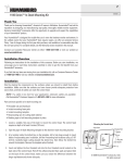
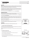
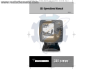
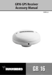
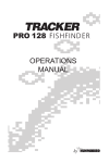
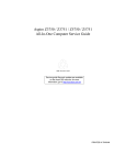
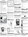
RF15 Operations Manual
Handle the RSS by the antenna tower when it has
been in water.
531393-1-A
Thank You!
NOTE: Each time the POWER-MENU key is pressed, the backlight momentarily illuminates for easy viewing at night.
Adjust the LIGHT menu setting to keep the backlight on.
NOTE: If Simulator Mode is selected from the Start-Up Menu and a transducer is plugged in, some menu setting
changes will be saved in memory even after the unit is powered down. Menu setting changes will not be saved from
Simulator mode when a transducer is not connected.
Thank you for choosing Humminbird®, America's #1 name in fishfinders. Humminbird® has built
its reputation by designing and manufacturing top-quality, thoroughly reliable marine equipment.
Your Humminbird® is designed for trouble-free use in even the harshest marine environment. In
the unlikely event that your Humminbird® does require repairs, we offer an exclusive Service
Policy-free of charge during the first year after purchase, and available at a reasonable rate after the
one-year period. For complete details, see the separate warranty card included with your unit. We
encourage you to read this operations manual carefully in order to get full benefit from all the
features and applications of your Humminbird® product.
Use a heavy test line,
standard knots, and
tackle such as a swivel.
The second leader hole is for using the RSS as a
float. Connect a lighter weight hook line to this
hole. Do not over-weight the hook line as this will
submerge the RSS, causing signal loss.
With this purchase you should have:
NOTE: Turning on the SetUp menu choice from the Main Menu System allows you to access additional set-up menu
choices. See SetUp Menu for more information.
If any of these components are missing or are not included, please contact our Customer Resource
Center at 1-334-687-0503 or visit our website at www.humminbird.com.
WARNING! This device should not be used as a navigational aid to prevent collision, grounding, boat damage, or
personal injury. When the boat is moving, water depth may change too quickly to allow time for you to react. Always
operate the boat at very slow speeds if you suspect shallow water or submerged objects.
WARNING! Disassembly and repair of this electronic unit should only be performed by authorized service
personnel. Any modification of the serial number or attempt to repair the original equipment or accessories by
unauthorized individuals will void the warranty. Handling and/or opening this unit may result in exposure to lead,
in the form of solder.
WARNING! This product contains lead, a chemical known to the state of California to cause cancer, birth defects
and other reproductive harm.
Using the RF15
Simply attach the RSS to the end of your fishing line and cast it into the water as you would a
normal float or lure, then power on the RF15 and you are ready to fish. Your RF15 uses sonar
technology to send sound waves from the RSS into the water.
To scan an area, cast and then reel in at a steady
rate with your rod tip up. Jerks may break water
contact, causing gapped signal input. A low rod
tip or heavy line may cause signal loss if the
RSS submerges.
CAUTION: You will increase the possibility of breaking your line if you use light test pound line on your reel. The RSS
is positively buoyant (is buoyant under its own weight plus 0.2 ounces of bait and lead weight.) The maximum amount
of weight for any attachment to the RSS is approximately 0.2 ounces (5.67 grams), and includes the combined
weight of any hook, line, weight, swivel/snap swivel and bait that is attached to the RSS. The RSS itself weighs 1
ounce, and therefore light test line might break.
Store the RSS in a dry, non-metallic container, such as a tackle box, in a separate compartment, and isolated from
any metallic devices.
WARNING! The bottom of the RSS should not be handled during sonar operation, as this may cause physical
discomfort and may result in personal injury in the form of tissue damage. Handle the RSS only by the antenna tower
when it has been in the water.
WARNING! The RSS (Remote Sonar Sensor) is not intended for use by children younger than 6 years old without
adult supervision as the RSS may represent a choking hazard to small children.
WARNING! Handling and/or opening this unit may result in exposure to lead, in the form of solder.
The Advanced Remote Sonar Sensor (RSS) has a non-replaceable Lithium battery with a shelf
life of three years that will last for approximately 500 hours of in-water use (when the nighttime
LED is turned off).
Discard the used RSS in compliance with local laws as you would any electronic component
or battery.
The RSS has contacts that perceive when the device is immersed in the water. These contacts
turn on the Sonar Transmitter/Receiver and begin transmitting the sonar information via RF to
the display. The RSS automatically stops using power a few seconds after being pulled out of
the water.
WARNING! Do not place the RSS in a wet area when not in use as this will turn on the RSS and shorten its
usable life. Store the RSS in a dry area when not in use to conserve power. Never place the RSS in a wet area
of a boat or on a metal surface that could accidentally power it on.
When you choose SetUp, additional menu choices will become available that are not a part of the
Main Menu system. After selecting SetUp, press the POWER-MENU key to display the SetUp menu
choices, one at a time. SetUp Menu choices include:
• Contrast
(Setting Not Saved in Memory)
• Fish ID+
Press the POWER-MENU key until LIGHT appears. Use the backlight for night fishing. Select either
0 (Off), or 1 through 5 to activate the backlight at the desired level. (0 to 5, Default = 0)
• Bottom View
• Battery Alarm
• Languages (International Units Only)
Sensitivity
• Units
(Setting Saved in Memory)
• Channel Select.
Press the POWER-MENU key until SENSITIVITY appears. Sensitivity controls how much detail is
shown on the display. Increasing the sensitivity shows more sonar returns from small baitfish and
suspended debris in the water; however, the display may become too cluttered. When operating in
very clear water or greater depths, increased sensitivity shows weaker returns that may be of
interest. Decreasing the sensitivity eliminates the clutter from the display that is sometimes present
in murky or muddy water. If Sensitivity is adjusted too low, the display may not show many sonar
returns that could be fish. (0 – 10, Default = 5)
Depth Range
Scroll through all SetUp menu choices to exit the SetUp menu.
Contrast (SetUp Menu)
(Setting Saved in Memory)
Make sure that the SetUp menu is selected, then press the POWER-MENU key until CONTRAST
appears. Select a setting from 1 through 5. (1 to 5, Default = 3)
Scroll through all SetUp menu choices to exit the SetUp menu.
Fish ID+ (SetUp Menu)
(Setting Not Saved in Memory)
RSS Power
Press the POWER-MENU key until SetUp appears. Select either Off or On.
(Off, On, Default = Off)
Light
NOTE: Continuous backlight operation will significantly decrease the battery life for RF15 Portables.
• RF15 Control Head
• One Advanced Remote Sonar Sensor - RSS
• Portable Carry Case
• This RF15 Operations Manual
SetUp Menu
(Setting Saved in Memory)
Press the POWER-MENU key until DEPTH RANGE appears. Automatic is the default setting. When
in automatic, the lower range will be adjusted by the unit to follow the bottom. (Auto, 10 to 120
Feet, Default = Auto)
NOTE: In manual operation, if the depth is greater than the depth range setting, the bottom will not be visible on the
display. Select AUTO to return to automatic operation.
Make sure that the SetUp menu is selected, then press the POWER-MENU key until FISH ID+
appears. Select either Off to view “raw” sonar returns, or On to view Fish symbols. Fish ID+ uses
advanced signal processing to interpret sonar returns, and will display a Fish Symbol when very
selective requirements are met. A select number of possible fish returns will be displayed with their
associated depth. (On, Off, Default = On)
Scroll through all SetUp menu choices to exit the SetUp menu.
Zoom
(Setting Not Saved in Memory)
Fish ID+
Press the POWER-MENU key until ZOOM appears. Select Auto to magnify the area around the
bottom in order to reveal fish and structure close to the bottom that may not be visible during
normal operation. When ZOOM is set to Auto, the upper and lower Depth Ranges are automatically
adjusted to keep the area above and below the bottom on the display. Select Off to return to normal
operation. (Off, Auto, Manual Ranges, Default = Off)
NOTE: If the RSS was used in salt water, rinse it with fresh water before storing it.
Powering ON and OFF
Upper Zoom
Range
Press and release the POWER-MENU key to power the RF15 on. Press and hold the POWER-MENU
key until the unit shuts down to power off.
Magnified Bottom
with More Detail
Raw Sonar
Bottom View (SetUp Menu)
(Setting Saved in Memory)
Make sure that the SetUp menu is selected, then press the POWER-MENU key until BOTTOM VIEW
appears. Bottom View selects the method used to represent the bottom and structure on the display.
(Structure ID, Black, WhiteLine, Inverse, Default = Inverse)
Structure ID® represents weak returns as light pixels and strong returns as
dark pixels. This has the benefit of ensuring that strong returns will be clearly
visible on the display.
Structure
Display
The returned “echoes” are transmitted with wireless technology to the display unit and plotted on
the LCD. New information appears on the right. As this information moves to the left a very accurate
picture of the underwater world is created, including the depth of underwater objects such as the
bottom, fish, and structures.
WARNING! The electronic parts in the Remote Sonar Sensor (RSS) are made to withstand use when casting into
water. Because shock from abrupt contact with rocks can damage your RSS, we recommend using your RSS in water
deeper than 1 foot only.
Surface Clutter
Upper Range
Water Surface Line
Depth – Measured at
the Transducer
Fish ID+ Symbols
Bottom Contour
Structure
Lower Range
Stationary Float: The RSS can be used as a float in a stationary location to monitor the area below,
giving you a live update as fish approach your bait.
Attaching the RSS
The line coming from your reel can be tied off to the front hole in the RSS. If you wish to also use the
RSS as a conventional float, use the second hole to attach your hook using a lighter weight line. A
snag will break the lighter line if you have to break free. Slip line techniques are not recommended
because of the higher risk of losing the RSS. If you do use the slip line method, use a lighter weight
line after the lower stop, enabling retrieval of the RSS if the lower line with hook breaks away.
Lower Zoom
Range
POWER/MENU Key
RIGHT Arrow Key
The Advanced RSS can be used in two distinct
ways:
Sonar Graph: The RSS can be used to
create a sonar graph of the bottom. Cast the
RSS into the water beyond an area of
interest. Retrieving the RSS slowly and
steadily will produce a screen detailing
structure, fish and bottom detail. Rhythmic
wave action and rocking may cause the
display of a rippled bottom.
Temperature
Black (Bottom Black) displays all pixels below the bottom contour as black,
regardless of signal strength. This has the benefit of providing a high contrast
between the bottom and other sonar returns on the display.
LEFT Arrow Key
There is also a series of manual ranges which can be selected. The manual depth ranges are
determined by the present depth conditions.
WhiteLine® highlights the strongest sonar returns in white resulting in a
distinctive outline. This has the benefit of clearly defining the bottom on the
display.
Fish Alarm
When the RF15 powers on, the Start-Up menu temporarily appears.
From this menu, use the arrow keys to select either Start-Up,
Simulator, or SetUp. If you do nothing, the unit will default to normal
on the water use.
• Use Start-Up for on the water use
• Use Simulator for learning how to use the system with simulated
sonar data; access Simulator by pressing the Right Arrow Key once
• Use SetUp to display additional set-up menu choices; access
SetUp by pressing the RIGHT Arrow Key twice (See SetUp Menu for
more information).
(Setting Saved in Memory)
Press the POWER-MENU key until FISH ALARM appears.
Select Off for no fish alarm, or one of the following symbols to set the alarm. An alarm will
sound when the RF15 detects fish that correspond to the alarm setting. Fish Alarm will only
sound if Fish ID+ is also set to On. (Off, Large, Large/Medium, All, Default = Off)
Large fish only
Large/Medium fish only.
All fish.
Scroll through all SetUp menu choices to exit the SetUp menu.
The Menu System
A simple menu system allows you to access your RF15’s adjustable settings. To activate the menu
system, press the POWER-MENU key. Press the POWER-MENU key repeatedly to display the RF15
menu settings, one at a time. When a menu setting is on the display, use the RIGHT and LEFT
Arrow keys to adjust the menu setting. Menu settings are removed from the screen automatically
after several seconds. In Normal operating mode, most menu settings saved to memory will not
return to their default values when the unit is turned off. See individual menu choices for more
information.
Inverse is a method where weak returns are shown with dark pixels and strong
returns with lighter pixels. This has the benefit of ensuring that weak signals will
be clearly visible on the display.
Filter
Battery Alarm (SetUp Menu)
(Setting Saved in Memory)
(Setting Saved in Memory)
Press the POWER-MENU key until FILTER appears. Select either Off or On. Filter adjusts the sonar
filter to limit interference on the display from sources such as your boat engine, turbulence, or other
sonar devices. (On, Off, Default = Off)
Make sure that the SetUp menu is selected, then press the POWER-MENU key until BATTERY ALARM
appears. Select Off or 8.5 to 13.5 Volts. Battery Alarm sounds when the input battery voltage is equal
to or less than the menu setting. (Off, 8.5 to 13.5 Volts, Default = Off)
Scroll through all SetUp menu choices to exit the SetUp menu.
Language (SetUp Menu: Int’l Only)
How the Wet Switch™ Works
(Setting Saved in Memory)
In the following sections, you will use the wet switch contacts on the bottom of the Advanced RSS
to enter programming mode and to change the Light and Channel settings. Before you try these
procedures for the first time, please read through this section to familiarize yourself with the way
the Wet Switch™ works.
Make sure that the SetUp menu is selected, then press the POWER-MENU key until LANGUAGE
appears (International Units Only). LANGUAGE selects the display language for menus. (Settings
vary, Default = English)
Scroll through all SetUp menu choices to exit the SetUp menu.
(Setting Saved in Memory)
Your finger should be moist, but not dripping, before
you touch the Wet Switch™. You can achieve the
correct dampness by dipping your finger in water,
then dabbing your finger twice on a towel.
Make sure that the SetUp menu is selected, then press the POWER-MENU key until UNITS
appears. UNITS selects the units of measure. (Feet/F, Meters/C, Fathoms/C, Default = Feet/F for
domestic units, and Meters/C for international units, where F stands for Fahrenheit and C stands
for Celsius)
Scroll through all SetUp menu choices to exit the SetUp menu.
A “touch” means touching both wet switch contacts
at the same time with your moistened finger, using
medium pressure. The time between touches needs
to be one second or less.
Units (SetUp Menu)
4. Use the SetUp Channel Select menu on the RF15 Control Head to switch the software to
match the new channel designation on the Advanced RSS. See Channel Select (SetUp
Menu) for more information.
CAUTION: Make sure that you change the Channel Selection on the Control Head to match the new Advanced RSS
Channel before using the Advanced RSS.
Using a First Generation RSS
First generation RSS units still sold with other SmartCast™ products come in two versions,
Channel A and Channel B (RF40A and RF40B), and are both compatible with the RF15.
NOTE: When using either an RF40A or RF40B RSS with the RF15, you will not get water temperature or grayscale
sonar information, and you will not be able to turn on the LED or change the channel on the RSS. You will still be able
to read digital depth and bottom contour information.
NOTE: When using an RF40A or RF40B RSS, make sure to select the matching channel from the CHANNEL
SELECT menu on the RF15 Control Head.
NOTE: Your finger must make contact with both of the wet switch pins simultaneously in order to tap them successfully.
Channel Select (SetUp Menu)
(Setting Saved in Memory)
See the procedures that follow for specific instructions on turning the light on or off or changing
the channel from A to B.
Make sure that the SetUp menu is selected, then press the POWER-MENU key until CHANNEL
SELECT appears. CHANNEL SELECT selects the type of RSS you are using. (A, B, Default = A)
Turning on the Advanced RSS Blinking Light
Scroll through all SetUp menu choices to exit the SetUp menu.
To turn on the blinking nighttime fishing light:
NOTE: The Channel Select setting must match the actual hardware configuration of your RSS in order for the
RSS to function. See Using the Advanced RSS for information about changing the channel of your Advanced
RSS manually using the wet switch on the Advanced RSS.
Channel A and B RSS Units
Your RF15 unit comes with an Advanced RSS. This Advanced RSS may be programmed to either
Channel A or Channel B. This A/B Channel option gives you the flexibility to switch to a different
channel if another angler is using a SmartCast™ unit within 150 feet of your RSS to reduce
possible interference. See Changing the Channel on the Advanced RSS for details on
selecting either Channel A or Channel B.
1. Wet your finger and tap the wet switch on the Advanced RSS three times (the time between
touches needs to be one second or less) to enter the Light programming mode. The RF15
temperature reading on the Control Head will change to show a temperature reading of 40°F
(4°C) (blinking light OFF).
2. To change the setting to 45°F (7°C) (blinking light ON) touch and release the wet switch
contacts once more. Wait two seconds and then confirm that the temperature reading on the
Control Head has changed to 45°F (7°C). Single touches will toggle the setting between
40°F (4°C) and 45°F (7°C).
NOTE: RSS units, regardless of channel, may generate erratic depth readings as a result of sonar interference when used
in close proximity (closer than 40 feet) to each other or to other sonar devices.
The Advanced RSS provides the following functionality:
When you are using the RF15, grayscale sonar data and water temperature will be displayed
automatically on the screen.
Default settings on new products are Light = OFF and Channel = A.
RSS Programming Mode
You may change the light setting or the channel type on the Advanced RSS using a programming
mode that is accessed by touching the wet switch contacts on the bottom of the RSS.
NOTE: Please read this and the next section BEFORE you try to program the Advanced RSS using the wet switch
contacts. Specific step-by-step procedures to turn on the light and to change the channel follow this section. You will find
it easier to perform these steps once you have grasped the way the programming mode works.
The programming mode allows you to:
• turn on the blinking light
• switch the Advanced RSS Channel from A to B.
The RF15 Control Head temperature readout provides user feedback to help you make the correct
selections. The temperature readout will change on the Control Head to 40°F (4°C), 45°F (7°C),
50°F (9°C) or 55°F (12°C) to signify the following settings.
NOTE: If the temperature readout is set for degrees Celsius then the temperature readout will change on the Control
Head to 4,7,9 or 12 to signify the following settings.
Light setting
Temp changes to… Means that…
40°F (4°C)
Blinking light is OFF (factory default)
45°F (7°C)
Blinking light is ON (but only blinks when the Advanced RSS is in the water)
Temperature of 40 Means LED is OFF
Temperature Setting of 45 Means LED is On
NOTE: When the LED is set to ON it will flash every four seconds when the RSS is in operation (i.e. when the wet
switch is submerged). Even when the LED is set to ON, the LED will not flash unless the wet switch is activated. If you
want to test the RSS to make sure the LED is set to ON before using the RSS, wet your finger and hold it on the wet
switch; if the LED is set to ON, the LED will begin to flash.
NOTE: Repeat steps 1 and 2 to turn off the LED when finished with night fishing.
3. Once you have made your selection you can either wait 20 seconds for programming mode
to time out (the Start-Up screen will appear on the Control Head display), or continue
immediately to the next procedure to change the channel.
Changing the Channel on the Advanced RSS
To change the channel type on the Advanced RSS:
1. From the Light programming mode (see Turning on the Advanced RSS Blinking Light), touch
and release the wet switch contacts twice more with your moist finger to change from the Light
programming mode to the Channel programming mode. The temperature reading on the
Control Head will change to show a temperature reading of 50°F (9°C) (channel set to A).
2. To change the setting to 55°F (12°C) (channel set to B) touch and release the wet switch
contacts once more. Wait two seconds and then confirm that the temperature reading on the
Control Head has changed to 55°F (12°C). Single touches will toggle the setting between
50°F (9°C) and 55°F (12°C).
55°F (12°C)
RSS is set to CHANNEL B
Temperature of 50 Means Channel is Set to A
After using the RSS in salt water, wipe the affected surfaces with a cloth dampened with fresh
water. The RSS Wet SwitchTM pins must be rinsed with fresh water after exposure to salt water
to prevent corrosion.
If sonar performance becomes weak (i.e., there are bottom gaps or "0" depth
readings) the bottom of the RSS needs to be cleaned with a drop or two of a 5 to
10 percent solution of liquid dishwashing detergent and water. Use approximately
one tablespoon detergent to 8 ounces of water to remove oils from the face of the
RSS, then wipe with a damp cloth.
Troubleshooting
Do not attempt to repair the RF15 yourself. There are no user-serviceable parts inside, and special
tools and techniques are required for assembly to ensure the waterproof integrity of the housing.
Repairs should be performed only by authorized Humminbird technicians.
Many requests for repair received by Humminbird involve units that do not actually need repair.
These units are returned “no problem found.” If you have a problem with your RF15, use the
following troubleshooting guide before calling the Customer Resource Center or sending your unit
in for repair.
NOTE: Retrieving the RSS too rapidly, or the repetitive rocking motion of rough water, can result in loss or distortion
of the bottom picture. This will cause intermittent screen display. For best bottom detail, perform a smooth and slow
reel-in with constant speed and the rod tip up (holding the rod tip low or using a heavy line may cause the RSS to
submerge and momentarily lose radio contact). The RSS has a maximum transmit range of 100 feet (30 meters). If
the unit is cast or drifts more than 100 feet away from the receiver, the signal may be inconsistent or lost. Raising the
RF15 control head slightly above ground level will also increase signal capture.
1. The RF15 loses signal.
If the RF15 is not able to get an RF signal from the RSS, the display will stop updating (the screen
will freeze) and the SmartCast™ screen will be displayed after several seconds. Whenever
reception is lost or the RSS emerges from the water for more than a few seconds, the SmartCast™
screen will be displayed until the RSS is placed back in the water and reception is regained.
Temperature of 55 Means Channel is Set to B
• The RSS may not obtain its maximum RF distance of 100 feet unless the water is smooth.
Waves or chop may reduce the RF range significantly.
3. Once you have made your selection, wait 20 seconds for programming mode to time out
(the Start-Up screen will appear on the Control Head).
3. The display shows fluctuating depth readings and excessive clutter, including vertical
bars that may be drawn on top of fish icons.
The RF15 system comes with the capability to receive separate signals from a Channel A RSS or
a Channel B RSS. Two A- or B-type RSS units used simultaneously, as well as one A- and one Btype RSS unit used simultaneously, can cause RF interference between each other.
4. The screen jumps and the bottom has an abrupt change; sometimes a vertical line is
missing or a black line from top to bottom is displayed.
This screen image jump is due to an automatic change in depth. New returns graphed at a different
scale will not match up with the historic data already graphed at a higher or lower scale. Vertical
lines can also occur as the radio signal from the RSS is lost and then regained in rough water
conditions.
International Purchases
A separate warranty is provided by international distributors for units purchased outside the United
States. This warranty is included by your local distributor and this distributor maintains local
service for your unit. Warranties are only valid in the area of intended distribution. Units purchased
in the United States or Canada must be returned to our factory in the United States for service.
RSS Maintenance
• Check the buoyant balance between the RSS and your tackle; over 0.2 ounce will submerge
the RSS, causing signal loss.
NOTE: The Advanced RSS programming mode will time out after 20 seconds of no user activity, display the StartUp screen, and return the RSS to normal operation.
The RSS will work reliably in water 2 feet (0.6 meters) or deeper. The depth is measured from the
RSS. A transmitter (RSS) to receiver (RF15) distance of greater than 100' may cause intermittent
screen display. Excessively rough water may cause the RSS to submerge, again losing contact.
Never leave the unit in a closed car or trunk—the extremely high temperatures generated in hot
weather can damage the electronics.
• Reeling the RSS too fast can cause loss of signal and the screen will freeze
IMPORTANT: The RF15 Control Head must be turned on and the CHANNEL SELECT SetUp menu on the Control
Head must be set to Channel A (even if the RSS is set to Channel B) before you can see the feedback on the Control
Head temperature readout.
NOTE: If the temperature display returns to a normal reading, or the Start-Up screen appears on the display, you are
no longer in programming mode.
When cleaning the LCD protective lens, use a chamois and non-abrasive, mild cleaner. Do not
wipe while dirt or grease is on the lens. Be careful to avoid scratching the lens.
• The RSS depth range is 2 to 120 feet (0.6 to 35 meters). Erratic readings may occur in
water that is shallower than 2 feet. In addition, because of the nature of sonar, this product
is not intended for use in swimming pools or small enclosed bodies of water.
Temp changes to… Means that…
RSS is set to CHANNEL A (factory default)
Do not use a chemical glass cleaner on the lens - this may cause cracking in the lens.
• The RSS uses line-of-sight wireless technology. If objects are placed between the RSS and
the RF15, reception may be lost.
Channel setting
50°F (9°C)
If the unit comes into contact with salt spray, wipe the affected surfaces with a cloth dampened in
fresh water.
Never leave the RSS in a closed car or trunk - the extremely high temperatures generated in hot
weather can damage the electronics.
• Blinking Light for nighttime use
• A/B Channel Select.
You must manually program the Advanced RSS in order to turn the light on or off or to change the
RSS channel setting to A or B.
Your RF15 is designed to provide years of trouble-free operation with virtually no maintenance.
Follow these simple procedures to ensure your RF15 continues to deliver top performance.
If your RSS remains out of the water for a long period of time, it may take some time to wet it
when returned to the water. Small air bubbles can cling to the surface of the RSS and interfere
with proper operation. Wipe the face of the RSS with a wet cloth to remove them.
Understanding the Advanced RSS
• Water Surface Temperature
• Grayscale Sonar Data
Maintenance
2. When in very shallow water, I get gaps in the bottom reading and inconsistent digital
depth indication.
SPECIFICATIONS
Power Requirement:
Control Head: ............................................................ Eight AA 1.5 Volt
Alkaline batteries (not included)
RSS: .................................................................... One non-replaceable
Lithium RSS Battery
Display Type .................................................................................... STN
Depth Capability .................................................................. 2 - 120 feet
(0.6 - 35 meters)
Sonar Coverage .............................................................. 90° @-10 dB*
Sonar Operating Frequency........................................................125 kHz
Operational Wireless Frequency ..............................................916.5 mHz
(433.92 mHz for European models)
Operational Range ................................................ 100 feet (30 meters)
Approval ......................................................................European models
are CE-approved.
*Area of bottom coverage equals twice the current depth.
CONTACT
HUMMINBIRD
Your Humminbird accessory is designed for
trouble-free operation and is backed by a one year warranty. If you have any
questions, contact our
Humminbird Customer Resource Center:
By Telephone
(Monday - Friday 8:00 a.m. to
4:30 p.m. Central Standard Time):
334-687-0503
By e-mail
(typically we respond to your e-mail within
three business days):
[email protected]
For direct shipping, our address is:
Humminbird
Service Department
678 Humminbird Lane
Eufaula, AL 36027 USA