1
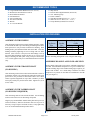
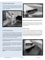
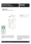
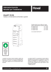
Tuf-Lite and Tuf-Lite II Fans 8000 Series Hub INSTALLATION MANUAL Adjustable Pitch Fan Assembly 34’ through 40’ Diameter Hudson Tuf-Lite® and Tuf-Lite II® fan blades Hudson Tuf-Lite® (black) fan blades are made from fiberglass reinforced epoxy resin having a very high strength-to-weight ratio and corrosion resistance (not shown). Hudson Tuf-Lite II® (blue) fan blades are made from fiberglass reinforced vinyl-ester resin having a very high strength-to-weight ratio and superior ultra-violet and corrosion resistance. An elastomeric blade/holder joint cover (not shown) prevents moisture from entering the blade (shown above). The individually balanced blades can be replaced independently – matched sets are not required. Installation Manual 8000 Page 1 of 8 January 2004 RECOMMENDED TOOLS z z z z z z z z Shop Towels Exact-A-Pitch® Digital Protractor (P/N 62375) 25 ft. Measuring Tape Pencil or Marker Open/Box End Wrench Set (1/2” - 1-1/2”) Socket Set for 1/2” Drive (1/2” - 1-1/2”) z Torque Wrench(s) Rated for 0-250 ft-lb. Long T-Handle Allen Wrench Set (3/16” to 3/8”) Medium Size Flat Head Screw Driver Brass Ball Peen Hammer Flat Bastard File 240 Grit Sand Paper Anti-Seize Lubricant WD-40 12” Crescent Wrench z z z z z z INSTALLATION PROCEDURES ASSEMBLY WITH BUSHING Clean all mating surfaces between hub, bushing and shaft. If there is no shoulder on shaft to prevent bushing from sliding down shaft, slide spacer/sleeve (not provided) on shaft before bushing. Slide bushing and key onto shaft until flush with end of shaft. Lock W-2 bushing on shaft by tightening set screw in flange with 1/4” Allen Wrench. (Note: setscrew is not present on all bushings) Line up key and set hub on bushing. Engage the four (4) 3/4” cap screws in flange of bushing into hub spool. Using a torque wrench with a 1-1/8” socket, tighten evenly to recommended standard of 250 ft-lb (dry). ASSEMBLY WITH STRAIGHT SHAFT (NO BUSHING) Clean all mating surfaces between the hub and the shaft. If there is no shoulder on shaft to prevent hub from sliding down shaft, slide spacer/sleeve (not provided) on shaft before hub or use a thrust retainer (optional equipment) on top of hub. Install key in shaft. Line up key and keyway and set hub on shaft. Tighten two (2) set screws in hub. Cap Screw Size 5/8” NC 3/4” NC 1” NC Socket Size 15/16” 1-1/8” 1-1/2” Torque Value (ft-lb) Lubricated Dry 100 110 125 130 150 160 NOTE: Retaining arrangement varies with gear shaft design. ASSEMBLE BLADE CLAMP ON BLADE NECK Remove blade clamp studs, lock washers, and blade clamp halves from hub. Assemble blade clamp halves over groove in blade neck, with thick leading edge to left and thin trailing edge to right as you stand at end of blade. Use a band clamp to hold the two blade clamp halves in position on the blade for installation in the hub body (See Figure 1). ASSEMBLY WITH TAPERED SHAFT (NO BUSHING REQUIRED) Clean all mating surfaces between hub and shaft. Coat all mating surfaces with an anti-seize or lubricating compound. Align keyways and install hub. Install retainer plate and cap screw(s) with lock washer(s). Shaft size determines what size cap screw is necessary. Using a torque wrench with a socket, evenly tighten cap screw to recommended standard per table below. Figure 1 Installation Manual 8000 Page 2 of 8 January 2004 INSTALL BLADE INTO HUB Hoist the blade into position. (Blade and clamp halves weight about 300 lbs.) Slide blade clamp into blade arm plates and install four (4) blade studs, eight (8) lockwashers and eight (8) nuts (See Figure 2). Tighten lightly. Figure 3 When bolts are tightened, hold a pencil against top end of blade and mark the level onto a fixed object, such as a pole or the fan ring. Install remaining blades at same place as first blade, following procedures above. After tightening bolts, mark top end of each blade in same place first blade was marked. If marks differ by 1-1/2”or more, adjust blade. Figure 2 CHECK TRACK SET PITCH AND TRACK Use Hudson EXACT-A-PITCH® digital protractor (Shown in Figure 3) or a bubble protractor to set blade pitch. Mount protractor on a flat bar as a base and place it approximately 1” from tip of blade. Note pitch on protractor. Rotate fan 360⋅, noting high and low pitch readings. Locate place where pitch reading is a mid-point between high and low readings, and set pitch at that point. After fan is installed in fan ring, outline top end of each blade onto fan ring with a marker. The difference between levels of highest and lowest outlines should not be more than 1-1/2”. Correct blade track by loosening clamp bolts and adjusting blade to match track of other blades. Retighten bolts and recheck track and pitch angle setting. Retighten blade clamp bolts to recommended standard of 280 ft-lb (lubricated) or 300 ft-lb (dry) torque (See Figure 4). Rotate blade in clamp until digital protractor shows specified pitch angle to within ±0.2⋅. (Fan pitch angle is shown on fan specification sheet for design duty.) After desired pitch angle is set, raise and lower end of fan blade and find midpoint of blade travel. Hold blade at the midpoint. Pull blade back so that it sits against blade clamp. Push blade to the right to remove all slack. Use torque wrench to tighten clamp bolts to recommended standard of 280 ft-lb (lubricated) or 300 ft-lb (dry). Recheck pitch setting. Blade must be set within ± 0.2⋅ of desired pitch angle. Tighten clamp bolts evenly. DO NOT OVER-TORQUE CLAMP BOLTS. Figure 4 Installation Manual 8000 Page 3 of 8 January 2004 ASSEMBLE SEAL DISC AND MOUNTING BOLTS Place seal-disc quarter section on hub, aligning the pear-shaped opening over one of the eye-bolts (See Figure 6) and drop the seal-disc quarter section onto the nearest group of seal-disc bracket stud pairs. Remove adhesive backing on nitrile gasket section and apply gasket to seal-disc flange surface carefully such that holes in gasket lineup with the holes in the flange (See Figure 7). Repeat these operations with the next three seal-disc quarter sections, ensuring that seal-disc balance match-marks are aligned. Figure 7 Make final adjustments to the quarter sections such they mate properly with each other and all seal-disc bracket studs, install the fasteners loosely joining each seal-disc section using one flat washer against the fiberglass surface on each side, one 3/8” hex bolt, lock washer, and hex nut at each flange hole location (See Figure 8). Ensure final fit-up of the seal-disc sections, check flatness and alignment of pear-shape openings with the eye-bolts, and snug all fasteners. Complete fasteners at each bracket location (two per bracket) using a 3/8” hex bolt, flat washer, lock washer, and hex nut (See Figure 9). Snug these fasteners. Figure 5 Figure 8 Figure 6 Installation Manual 8000 Using a measuring tape in several radial locations, double-check the seal-disc assembly such that it is centrally located on the hub. Make any final adjustments as necessary to ensure concentricity and trueness then tighten all fasteners at the flange surfaces and bracket studs to 15 ft-lbs lubricated or 20 ft-lbs non-lubricated. Make sure that all other details of fan installation is complete and be sure to remove all tools, loose parts, and materials from the completed hub assembly prior to startup. Page 4 of 8 January 2004 TIP CLEARANCE Figure 9 Figure 11 OPERATING INSTRUCTIONS Start fan and check rotation. Viewed from top, fan blades should rotate clockwise. Check motor power consumption to be sure fan is pulling desired load. CAUTION: If positive pitch is set in summer to use all available motor amps (nameplate rating), motor could be overloaded in winter. Design pitch angles usually do not use all of the available motor horsepower. This ensures that the motors will not be overloaded at low winter temperatures. Figure 10 NOTE: The purpose of the seal disc is to prevent hot air from recirculating back down through the hub, increasing efficiency. CHECK TIP CLEARANCE SPACERS Rotate fan in position inside fan ring or fan stack to check tip clearance. Check for spots where fan blade clearance is less than 3/4” or greater than 1-1/2” from fan ring (See Figure 11). If necessary adjust fan ring or fan stack by shimming to obtain proper clearance. Note that different cooling towers may have different ways to adjust the fan ring or fan stack. Figure 12 Installation Manual 8000 Page 5 of 8 January 2004 PARTS LIST 8000 Series Hub - Adjustable Pitch Fan Assembly (34’ through 40’ Diameter) PARTS LIST ITEM DESCRIPTION Up to 7.44 Diameter Shaft 1 ITEM 2 3 4 5 6 7 8 9 10 11 12 13 14 15 16 17 18 19 20 21 22 23 24 25 26 27 28 29 30 31 32 33 34 35 Hub Plate (2 Per Hub) W-2 DESCRIPTION TYPE Hub Spool W-1 Bushing W-1 Blade Clamp Half (Epoxy Coated Aluminum) Blade Clamp Stud W/ 2 Nuts 1”-8 x 14 1/2” (Mech. Galv.) 1” Flat washer (Mech. Galv.) 1” Lock washer (Mech. Galv.) Hub Spool Cap Screw 3/4”-10 x 2 1/2” (316 SS) 3/4” Flat washer (316 SS) 3/4” Lock washer (316 SS) Blade Arm, Bottom, 44” Long Blade Arm Stiffener, 30 5/16” Long Blade Arm Assy, Top Bolt, HH, 1”-8 x 3” (Mech. Galv.) Bolt, HH, 1”-8 x 2 1/2” (Mech. Galv.) Nut, Heavy Hex, 1”-8NC (Mech. Galv.) 1” Flat washer (Mech. Galv.) 1” Lock washer (Mech. Galv.) Seal Disc Bracket Weldment Cap Screw, HH, 3/8”-16NC x 3/4” (316 SS) 3/8” Lock Washer (316 SS) Seal Disc Washer, 1/8” Thick, Nitrile Seal Disc Mounting Flat Washer, 3/8” x 1 1/2” OD (316 SS) Seal Disc Mounting Lock Washer, 3/8” (316 SS) Eye Bolt W/ Nut 3/4”-10 x 2” (Mech. Galv.) 3/4” Flat Washer (Mech. Galv.) 3/4” Lock Washer (Mech. Galv.) Pin, Grooved, 1/2” X 1-1/2” 160” Diameter Seal Disc Kit * Seal Disc Joint Gasket Seal Disc Cap Screw, HH, 3/8”-16NC x 2” (316 SS) Seal Disc Hex Nut, 3/8” (316 SS) Seal Disc Flat Washer 3/8” x 1” OD (316 SS) Seal Disc Lock Washer 3/8” (316 SS) Tuf-Lite II Fan Blade (Blue) TYPE W-2 PART. NO Hub Assy. No. Part. No. Part. No PART. NO 65060 Specify Bore 65018 70643 57402 73742 57027 73720 73739 61650 61660 D8127 59815 69927 72120 57402 73742 B8136 70033 73722 73055 60273 73722 59547 16716 73738 74540 D8053 73047 53622 72050 73623 73722 (Varies) (Varies) Tuf-Lite Fan Blade (Black) * Includes all 316 SS hardware (items 22 thru 24 & 30 thru 34) to assembly and mount. Installation Manual 8000 Page 6 of 8 NO OF BLADES 6 7 8 9 10 11 12 13 14 8906 8907 8908 8909 8910 8911 8912 8913 8914 D8116 D8117 D8118 D8119 D8120 D8121 D6072 D8123 D8124 D8126 D8135 D8128 D8129 D8130 D8131 D8132 D8133 D8134 QUANTITY PER ASSEMBLY 1 1 1 1 1 1 1 1 1 1 1 1 1 1 1 1 1 1 12 14 16 18 20 22 24 26 28 24 28 32 36 40 44 48 52 56 48 56 64 72 80 88 96 104 112 48 56 64 72 80 88 96 104 112 16 16 16 16 16 16 16 16 16 16 16 16 16 16 16 16 16 16 16 16 16 16 16 16 16 16 16 6 7 8 9 10 11 12 13 14 12 14 16 18 20 22 24 26 28 6 7 8 9 10 11 12 13 14 48 56 64 72 80 88 96 104 112 24 28 32 36 40 44 48 52 56 72 84 96 108 120 132 144 156 168 144 168 192 216 240 264 288 312 336 72 84 96 108 120 132 144 156 168 8 8 8 8 8 8 8 8 8 16 16 16 16 16 16 16 16 16 16 16 16 16 16 16 16 16 16 16 16 16 16 16 16 16 16 16 16 16 16 16 16 16 16 16 16 16 16 16 16 16 16 16 16 16 4 4 4 4 4 4 4 4 4 8 8 8 8 8 8 8 8 8 4 4 4 4 4 4 4 4 4 4 4 4 4 4 4 4 4 4 1 1 1 1 1 1 1 1 1 4 4 4 4 4 4 4 4 4 24 24 24 24 24 24 24 24 24 24 24 24 24 24 24 24 24 24 48 48 48 48 48 48 48 48 48 24 24 24 24 24 24 24 24 24 6 7 8 9 10 11 12 13 14 6 7 8 9 10 11 12 13 January 2004 14 Installation Manual 8000 Page 7 of 8 January 2004 EXAMPLE: Blades: Hub Spool: Plates: Bushing: Seal Disc: 23 22 1 10 9 8 Fan Model Adjustable Pitch APT 2 32 3 31 30 FAN SHAFT 12 28 14 18 17 16 25 26 27 18 17 16 15 20 21 Fasteners: Blade Clamps: STD. MATERIALS & FINISHES: 33 13 11 4 5 7 35 10 Number of Blades Adjustable Pitch Fan Assembly 34’ Thru 40’ Diameter Series 8000 HUB HUDSON PRODUCTS CORPORATION Fan Diameter and Blade Type (Specify “H” for Tuf-Lite II® Blades) (Specify “B” for Tuf-Lite® Blades) 40B 29 Epoxy Coated Aluminum (Std) Ductile Iron (Optional) Steel, Mech. Galvanized & 316 SS Complete Fan W/316 SS (Optional) Complete Fan W/K500 Monel (Optional) 19 6 Shaft Diameter 6 1/2” BORE When Ordering, Specify Fan Diameter, Type and Number of Blades and Shaft Diameter Fiberglass Reinforced Vinyl Ester Ductile Iron, Zinc Rich Coating Steel, Coal Tar Epoxy Malleable Iron Fiberglass Reinforced Polyester 24 34 1307 Soldiers Field Drive Sugar Land, Texas 77479-4072 Post Office Box 20029 Sugar Land, Texas 7777496-0029 Phone: (281) 275-8100 Fax: (281) 275-8388 1-800-634-9160 (24 Hours) EMAIL: [email protected] http://www.hudsonproducts.com Hudson, Auto-Variable, Combin-Aire, Exact-A-Pitch, Fin-Fan, Heatflo, Hy-Fin, Split-Flo, Solo Aire, Stac-Flo, Steamflo, Thermflo, Tuf-Edge, Tuf-Lite, and Tuf-Lite II are registered trademarks of Hudson Products Corporation. Installation Manual 8000 Page 8 of 8 January 2004