1
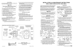
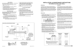
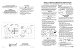
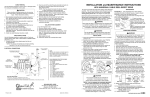
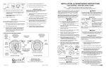
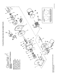
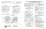
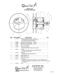
CABLE REMOVAL
Use the following procedure to remove worn or damaged cable
from reel prior to installation of new cable.
2. Feed one end of the cable through water-tight connector on
the main shaft inside the spool and into the slip ring side.
(See drawing below).
NOTE: This may require that jacket of cable be stripped
to allow conductors to pass through shaft.
3. Connect individual conductors to appropriate rings on
collector using crimp fitting or similar connection method.
4. Tighten water-tight connector and U-bolt provided on
drum wrapper segment. Do not over-tighten.
5. Wind the cable onto the reel spool by hand rotating
spool in direction it turns free of spring tension.
6. Connect free end of cable to machine junction box.
7. Pretension reel and complete installation as
previously described.
CAUTION
Failure to relieve all spring tension prior to removing
cable could result in damage to equipment or personal
injury. Follow instructions carefully.
1. Move machine serviced by reel to a position closest to
reel. Springs will still be under pre-tension at this point.
2. Turn off all electric power.
3. Lock spool to prevent turning using either a spool lock
mechanism or by tying off.
4. Disconnect cable from machine junction box.
5. Grip spool by hand and carefully release spool lock or
tie. Slowly unwind remaining tension.
6. Again lock or tie spool to prevent rotation.
7. Remove cable from spool. Loosen U-bolt and water-tight
connector and disconnect conductors from slip ring.
8. Install new cable following instruction at right.
COLLECTOR REPLACEMENT
1. Turn off all power to reel.
2. Remove collector cover and gasket.
3. Disconnect electric leads to and from collector.
4. Remove drive stud bolt from bearing housing.
5. Remove button plug from hole in side of housing. Insert
long 1/8” Allen wrench through hole and loosen two set
screws in collector locking collar Set screws are at 90O
to one another..
NOTE: Older reels may have lock screws which must be
removed to reach set screws holding collector to shaft.
6. Slide collector off shaft.
7. Install new collector by reversing above steps.
CABLE INSTALLATION
Use the following procedure to replace cable or if reel was
ordered without cable. Refer to CABLE INSTALLATION
REFERENCE DRAWING, below.
1. Unspool new cable from shipping spool and lay out
to eliminate twist.
NOTE: This step is not essential, but will aid in winding
operation of the reel and prolong cable life.
CABLE INSTALLATION REFERENCE DRAWING
INSTALL CABLE
THIS DIRECTION
TERMINATE THIS END TO
MACHINE JUNCTION BOX
ATTACH INDIVIDUAL
CONDUCTORS TO
COLLECTOR LEADS
AT THIS END
BUTTON
PLUG
POSITION CABLE
GUIDE SO THAT
ROLLER PLATE
FACES CABLE PAYOFF DIRECTION.
CABLE
U-BOLT
SPOOL ROTATION DIRECTION
TO WIND CABLE WHEN
VIEWED FROM SPRING SIDE
(STANDARD ROTATION)
WATER- TIGHT
CONNECTOR
LINE
ENTRANCE
(NPT)
PAYOFF
DIRECTION–
OPTIONAL
GUIDE
LOCATION
INSTALLATION and MAINTENANCE INSTRUCTIONS
MMD21 DIRECT DRIVE ELECTRIC CABLE REELS
All units are provided with right hand rotation unless otherwise
specified. This means that cable is pulled off spool top left or
bottom right (spool rotates clockwise to wind cable) when
viewing spring end of reel. See diagram on parts page.
Clock-type springs provide power for automatic cable take-up.
Spring must be pretensioned at time of installation to
insure that tension is applied to cable at all times. A tension
adjustment spanner wrench is provided with each reel.
WARNING
Some reels with large or multiple springs are equipped with
a ratcheted adjustment wrench. Follow separate instructions for its use. Failure to use ratcheted wrench, on reels
so equipped, could result in serious personal injury.
SPRING REPLACEMENT
WARNING
Do not attempt to relieve spring tension using spanner wrench. Doing so may result in personal injury.
INSTALLATION
1. Insure that machinery to be serviced by reel is at position
closest to reel.
2. Securely mount reel in desired position using 3/8"(M10)
bolts.Be sure spool is aligned with cable run.
3. Position optional cable guide, if reel is so equipped.
See CABLE INSTALLATION DRAWING.
4. Connect free end of cable to junction box on machine or
adjust cable stop so that desired length of cable
extends from reel.
5. Remove cover plate on spring housing to expose
shaft and spring hub. (See Figure 1).
6. Insert spanner wrench into holes in spring hub (Fig 2).
Rotate wrench counterclockwise (for standard rotation).
Number of 360O turns should match last digit in model
number on serial plate. If model number includes an “R”,
reel is reverse rotation and wrench must be rotated
clockwise. (See EXPLANATION on parts list page.)
PAYOFF
DIRECTION
REMOVE
COVER
PLATE
SPRING
MOTOR
SPRING MOTOR
Figure 1
SLIP RING
ASSEMBLY
HOOP GUIDE
SPOOL
MAIN SHAFT
®
®
HUBBELL
Printed in USA
COUNTERCLOCKWISE
FOR STANDARD
ROTATION
SPRING
HOUSING
PRETENSION
HUB
COLLECTOR
COVER
A Hubbell Company
PAYOFF
DIRECTION–
OPTIONAL
GUIDE
LOCATION
SPRING
HUB
Figure 2
SPANNER
WRENCH
CAUTION
Do not exceed number of turns indicated on
serial plate. Over-tensioning can cause a
broken spring, sheared shaft or other damage.
NOTE: If reel is equipped with ratcheted adjustment
wrench, follow instructions on separate sheet.
NOTE: On reels containing more than one spring, the hubs
are connected at the factory. Therefore, by tightening the
outer spring, the inside spring(s) will be tightened.
7. Remove collector cover and connect individual supply
conductors to collector terminals. See ELECTRICAL
CONNECTIONS diagram, on parts page.
GLEASON REEL CORP.
P.O. Box 26 • 600 South Clark St.
Mayville, WI 53050–0026
Phone 920–387–4120 • Fax 920–387–4189
Bulletin No. 040259.a
MAINTENANCE
Periodically: A. Use compressed air to clean collector
assembly and inside of collector housing. Inspect collector
assembly for brush wear and pitted slip rings.
B. Inspect cable for wear and check mounting bolts and
“IN” with 2/3 BROKEN SPRING
other hardware for tightness.
cable off reel–
INDICATORS
C.Check for broken springs
SPRING OK
by pulling about 2/3 cable off
reel and observing “Broken
“OUT” with 2/3
Spring Indicators” on sides of
cable off reel–
spring canisters (Fig 3).
SPRING
NOTE: Bearings and springs
BROKEN
are prelubricated and require
Figure 3
no periodic maintenance.
WARNING
Do not attempt to remove spring from its housing. Clocktype springs can be dangerous to handle. Removal of
spring from housing could result in personal injury.
The unique SAFETYCHANGE® spring motor consists of a
spring and hub sealed within a housing. A replacement spring
is supplied sealed in its housing and the old unit should be discarded completely.
1. Turn off all electric power.
2. Disconnect cable from machine junction box.
3. Wind all cable onto reel to relieve all spring tension.
4. Remove inspection cover from face of spring housing.
5. Rotate spool clockwise and observe inner shaft. Shaft
should rotate clockwise and hub (with spring attached)
should remain stationary.
NOTE: Do not attempt to remove spring if resistance
is met or hub tends to rotate with shaft.
Continue to rotate spool and strike end of shaft
several sharp blows with a lead hammer or rubber mallet
until shaft rotates freely and hub remains stationary.
6. Remove (4) nuts which secure spring motor(s) to frame.
7. Slide spring motor(s) off shaft and discard.
NOTE: On multi-spring reels, be sure to remove and save
dowel pins which connect one spring hub with another. Also
remove snap rings on shaft between spring housings.
8. Install replacement spring motor(s), pawls and pawl springs.
NOTE: Pawl springs must be located between the pawls
and the deepest section of the shaft grooves. Make sure
that pawls and pawl springs are inserted flush with ends of
shaft and hub or they may rub against inspection cover.
SPOOL
SHAFT
SIDE VIEW
SPRING
HUB
(Spring not
shown)
PAWL
SPRING
Install
against flat
END VIEW
SHAFT
GROOVE
9. Tighten nuts (and extension bolts) securing spring
housing(s) to reel frame.
10. Connect free end of cable to junction box on machine or
adjust cord stop so that desired length of cord extends from reel.
11. Tension spring with spanner wrench. Refer to
INSTALLATION section.
12. Replace inspection cover.
CONTINUED ON BACK PAGE
ILLUSTRATED PARTS LIST
MMD21 DIRECT DRIVE ELECTRIC CABLE REELS
28
1
MMD21 DIRECT DRIVE ELECTRIC CABLE REEL REPLACEMENT PARTS LIST
4
Always specify SERIAL NUMBER &
MODEL NUMBER when ordering parts.
NOTE: Applicable mounting hardware included with each kit.
1
11
12
12
11
21
ITEM
6
7
22
11
12
12
11
KIT NO.
11
3
13
8
2
3
10
15
27
14
19
20
20
29
8
9
3
3
5
8
9
3
25
26
27
1
24
1
23
16
1
11
12
12
7
TO DETERMINE ROTATION OF REEL
11
12
11
12
17
18
11
STANDARD
REVERSE
ROTATION
ROTATION
Cable is payed out and retracted as shown
when viewing reel from spring motor side.
15
19
20
CABLE LEADWIRES
MOVING END
ELECTRICAL CONNECTIONS
CABLE
LEADWIRE INPUT FIXED END
(CUSTOMER SUPPLIED)
SLIP-RING
LEADWIRES ARE
NUMBER TAGGED
SLIP-RING LEAD TO
MOVING CABLE
CONNECTIONS
BRUSH TERMINAL
CONNECTIONS
2
1
1
WATER–TIGHT
CABLE GRIP
3
2
SET
SCREW
4
3
4
REEL
MAINSHAFT
COLLAR
SLIP–RINGS
SPOOL
SLIP–RING
COVER
FRAME
SLIP–RING ENCLOSURE
• 600 VOLT AC.
250 VOLT DC. WATERTIGHT, DUST TIGHT.
• DO NOT EXCEED AMPERAGE RATING OF CABLE OR SLIP RING.
• NUMBER OF CIRCUITS MAY VARY FROM TWO (MINIMUM) TO 36 (MAXIMUM). FOUR CIRCUITS SHOWN.
NOTE:
Wire size, wire connectors, connection
sequence, and connection methods must comply
with National Electrical code and Local Electrical
ordinances. If in doubt, contact a local electrical
contractor or electrical inspector.
COLOR SEQUENCE FOR TYPE SO CABLE
THREE CONDUCTOR CABLE
# 1 – BLACK
# 2 – WHITE
# 3 – GREEN (ground)
FOUR THRU TWELVE CONDUCTOR CABLE
# 1 – BLACK
# 2 – WHITE
# 3 – RED
# 4 – GREEN (ground)
# 5 – ORANGE
# 6 – BLUE
# 7 – WHITE W/ BLACK TRACER
# 8 – RED W/ BLACK TRACER
# 9 – GREEN W/ BLACK TRACER
#10 – ORANGE W/ BLACK TRACER
#11 – BLUE W/ BLACK TRACER
#12 – BLACK W/ WHITE TRACER
KIT NO.
DESCRIPTION
QTY.
1
20
P06-03
ESNA Lock Nut, .50-13, Z.P.
ar
2
012406
Discs (Set of two)
1
21
021762
Hub Lock Pins
ar
3
012397
1
22
012457
Button Plug
23
23
23
23
23
23
23
23
23
23
23
23
23
23
23
23
23
23
23
23
23
23
23
23
23
23
012285
012286
012287
012288
012289
012290
012291
012292
012293
012294
012295
012296
012297
012298
012299
012300
012376
012377
037194
037294
037295
012304
012381
012382
012383
012384
Collector Assembly,
Collector Assembly,
Collector Assembly,
Collector Assembly,
Collector Assembly,
Collector Assembly,
Collector Assembly,
Collector Assembly,
Collector Assembly,
Collector Assembly,
Collector Assembly,
Collector Assembly,
Collector Assembly,
Collector Assembly,
Collector Assembly,
Collector Assembly,
Collector Assembly,
Collector Assembly,
Collector Assembly,
Collector Assembly,
Collector Assembly,
Collector Assembly,
Collector Assembly,
Collector Assembly,
Collector Assembly,
Collector Assembly,
24
012440
24
24
012441
012443
25
012409
25
25
25
25
25
012410
012411
012412
012413
012414
Collector Cover Kit (8" long)
(Includes seal ring)
Collector Cover Kit (10.5" long)
Collector Cover Kit (13" long)
Collector Cover Kit (15.5" long)
Collector Cover Kit (20.5" long)
Collector Cover Kit (28.5" long)
Main Shaft Assembly
(Includes drive pin and retaining rings)
4
012402
Bearing Kit–2" Bore
(Includes housing and gasket)
1
5
012401
Bearing Kit–1.75" Bore
(Includes housing and gasket)
1
1
2 Pole, 35 Amp
3 Pole, 35 Amp
4 Pole, 35 Amp
6 Pole, 35 Amp
8 Pole, 35 Amp
10 Pole, 35 Amp
12 Pole, 35 Amp
14 Pole, 35 Amp
16 Pole, 35 Amp
20 Pole, 35 Amp
24 Pole, 35 Amp
30 Pole, 35 Amp
36 Pole, 35 Amp
2 Pole, 75 Amp
3 Pole, 75 Amp
4 Pole, 75 Amp
6 Pole, 75 Amp
8 Pole, 75 Amp
2 Pole, 125 Amp
3 Pole, 125 Amp
4 Pole, 125 Amp
2 Pole, 200 Amp
3 Pole, 200 Amp
4 Pole, 200 Amp
6 Pole, 200 Amp
8 Pole, 200 Amp
1
1
1
1
1
1
1
1
1
1
1
1
1
1
1
1
1
1
1
1
1
1
1
1
1
1
6
012456
Drive Stud Kit
1
7
7
7
7
7
7
7
7
012213
01221301
012214
01221401
012371
01237101
014619
01461901
Stub
Stub
Stub
Stub
Stub
Stub
Stub
Stub
1
1
1
1
1
1
1
1
8
012416
Wrapper Kit–5" Wide, 8" to 14" Dia.
(Includes 4 wrapper sections)
1
8
012417
Wrapper Kit–5" Wide, 15" to 20"Dia.
(Includes 8 wrapper sections)
1
9
012444
1
9
9
012445
012446
Cable Clamp Kit .38–.74 Dia. Cable
(U-bolt with lockwashers and hex nuts)
Cable Clamp Kit .75–1.11 Dia. Cable
Cable Clamp Kit 1.12–1.50 Dia. Cable
10
10
10
10
10
10
10
10
10
012459
012460
012461
012462
012463
012464
012465
012466
012467
11
11
017051
Spring Motor Kit, Std. Rot.–100
ar
(Includes pawl, pawl springs, cover, gaskets, and snap ring)
017052
Spring Motor Kit, Rev. Rot.–100
ar
12
012427
26
012458
Seal Ring (only)
1
13
017191
Spanner Wrench
1
27
012096
Hoop Kit
1
14
032804
Ratchet Wrench KIt
(Includes mounting bolts)
1
28
012091
Spool Lock Assembly
1
15
017055
Extension Bolts
(4 bolts per kit–less hardware)
ar
29
015659
16
016182
Carriage Bolt, .50-13 x 1.5
ar
17
021291
Lockwasher, .56 med, Z.P.
ar
18
100959
Hex Nut, .50-13, Z.P.
ar
19
101211
Flat Washer, .50
ar
11
11
ITEM
Frame Assembly
1
15
QTY.
012393
2
14
DESCRIPTION
1
Shaft,
Shaft,
Shaft,
Shaft,
Shaft,
Shaft,
Shaft,
Shaft,
Cable
Cable
Cable
Cable
Cable
Cable
Cable
Cable
Cable
Std. Rotation (1001)
Rev. Rotation (1001)
Std. Rotation (1002)
Rev. Rotation (1002)
Std. Rotation (1003)
Rev. Rotation (1003)
Std. Rotation (1004)
Rev. Rotation (1004)
Connector
Connector
Connector
Connector
Connector
Connector
Connector
Connector
Connector
.38–.50 Cable Dia.
.50–.62 Cable Dia.
.62–.75 Cable Dia.
.75–.88 Cable Dia.
.88–1.00 Cable Dia.
1.00–1.12 Cable Dia.
1.12–1.25 Cable Dia.
1.25–1.38 Cable Dia.
1.38–1.50 Cable Dia.
Pawl Kit
(Includes 2 pawls and springs)
1
1
1
1
1
1
1
1
1
1
1
ar
Brush Kit (35 Amp)
(Each kit includes 4 brushes and 4 fingers)
Brush Kit (75 Amp)
Brush Kit (125 Amp/200 Amp)
MMD
FRAME
SERIES
SPRING
SERIES
21 100
NO. OF
SPRINGS
ar
ar
1
1
1
1
1
1
Entrance Assembly Kit–1.25 NPT
1
(Includes Pipe Nipple, Condulet and Dome Cover)
NOTE:
Please consult factory for optional accessories: roller guides, ratchet lock, limit
switch, and swivel base.
MODEL NUMBER EXPLANATION
MILL DUTY
REEL
ar
NO. OF
POLES
2 R - 12
INDICATES REVERSE ROTATION.
NO LETTER INDICATES STANDARD ROTATION.
AMPACITY
3
AMPACITY
CORE
DIAMETER
10 -
PRETENSION
TURNS
1
CODE
AMPS
3
35
7
75
12
125
20
200
ILLUSTRATED PARTS LIST
MMD21 DIRECT DRIVE ELECTRIC CABLE REELS
28
1
MMD21 DIRECT DRIVE ELECTRIC CABLE REEL REPLACEMENT PARTS LIST
4
Always specify SERIAL NUMBER &
MODEL NUMBER when ordering parts.
NOTE: Applicable mounting hardware included with each kit.
1
11
12
12
11
21
ITEM
6
7
22
11
12
12
11
KIT NO.
11
3
13
8
2
3
10
15
27
14
19
20
20
29
8
9
3
3
5
8
9
3
25
26
27
1
24
1
23
16
1
11
12
12
7
TO DETERMINE ROTATION OF REEL
11
12
11
12
17
18
11
STANDARD
REVERSE
ROTATION
ROTATION
Cable is payed out and retracted as shown
when viewing reel from spring motor side.
15
19
20
CABLE LEADWIRES
MOVING END
ELECTRICAL CONNECTIONS
CABLE
LEADWIRE INPUT FIXED END
(CUSTOMER SUPPLIED)
SLIP-RING
LEADWIRES ARE
NUMBER TAGGED
SLIP-RING LEAD TO
MOVING CABLE
CONNECTIONS
BRUSH TERMINAL
CONNECTIONS
2
1
1
WATER–TIGHT
CABLE GRIP
3
2
SET
SCREW
4
3
4
REEL
MAINSHAFT
COLLAR
SLIP–RINGS
SPOOL
SLIP–RING
COVER
FRAME
SLIP–RING ENCLOSURE
• 600 VOLT AC.
250 VOLT DC. WATERTIGHT, DUST TIGHT.
• DO NOT EXCEED AMPERAGE RATING OF CABLE OR SLIP RING.
• NUMBER OF CIRCUITS MAY VARY FROM TWO (MINIMUM) TO 36 (MAXIMUM). FOUR CIRCUITS SHOWN.
NOTE:
Wire size, wire connectors, connection
sequence, and connection methods must comply
with National Electrical code and Local Electrical
ordinances. If in doubt, contact a local electrical
contractor or electrical inspector.
COLOR SEQUENCE FOR TYPE SO CABLE
THREE CONDUCTOR CABLE
# 1 – BLACK
# 2 – WHITE
# 3 – GREEN (ground)
FOUR THRU TWELVE CONDUCTOR CABLE
# 1 – BLACK
# 2 – WHITE
# 3 – RED
# 4 – GREEN (ground)
# 5 – ORANGE
# 6 – BLUE
# 7 – WHITE W/ BLACK TRACER
# 8 – RED W/ BLACK TRACER
# 9 – GREEN W/ BLACK TRACER
#10 – ORANGE W/ BLACK TRACER
#11 – BLUE W/ BLACK TRACER
#12 – BLACK W/ WHITE TRACER
KIT NO.
DESCRIPTION
QTY.
1
20
P06-03
ESNA Lock Nut, .50-13, Z.P.
ar
2
012406
Discs (Set of two)
1
21
021762
Hub Lock Pins
ar
3
012397
1
22
012457
Button Plug
23
23
23
23
23
23
23
23
23
23
23
23
23
23
23
23
23
23
23
23
23
23
23
23
23
23
012285
012286
012287
012288
012289
012290
012291
012292
012293
012294
012295
012296
012297
012298
012299
012300
012376
012377
037194
037294
037295
012304
012381
012382
012383
012384
Collector Assembly,
Collector Assembly,
Collector Assembly,
Collector Assembly,
Collector Assembly,
Collector Assembly,
Collector Assembly,
Collector Assembly,
Collector Assembly,
Collector Assembly,
Collector Assembly,
Collector Assembly,
Collector Assembly,
Collector Assembly,
Collector Assembly,
Collector Assembly,
Collector Assembly,
Collector Assembly,
Collector Assembly,
Collector Assembly,
Collector Assembly,
Collector Assembly,
Collector Assembly,
Collector Assembly,
Collector Assembly,
Collector Assembly,
24
012440
24
24
012441
012443
25
012409
25
25
25
25
25
012410
012411
012412
012413
012414
Collector Cover Kit (8" long)
(Includes seal ring)
Collector Cover Kit (10.5" long)
Collector Cover Kit (13" long)
Collector Cover Kit (15.5" long)
Collector Cover Kit (20.5" long)
Collector Cover Kit (28.5" long)
Main Shaft Assembly
(Includes drive pin and retaining rings)
1
2 Pole, 35 Amp
3 Pole, 35 Amp
4 Pole, 35 Amp
6 Pole, 35 Amp
8 Pole, 35 Amp
10 Pole, 35 Amp
12 Pole, 35 Amp
14 Pole, 35 Amp
16 Pole, 35 Amp
20 Pole, 35 Amp
24 Pole, 35 Amp
30 Pole, 35 Amp
36 Pole, 35 Amp
2 Pole, 75 Amp
3 Pole, 75 Amp
4 Pole, 75 Amp
6 Pole, 75 Amp
8 Pole, 75 Amp
2 Pole, 125 Amp
3 Pole, 125 Amp
4 Pole, 125 Amp
2 Pole, 200 Amp
3 Pole, 200 Amp
4 Pole, 200 Amp
6 Pole, 200 Amp
8 Pole, 200 Amp
1
1
1
1
1
1
1
1
1
1
1
1
1
1
1
1
1
1
1
1
1
1
1
1
1
1
4
012402
Bearing Kit–2" Bore
(Includes housing and gasket)
1
5
012401
Bearing Kit–1.75" Bore
(Includes housing and gasket)
1
6
012456
Drive Stud Kit
1
7
7
7
7
7
7
7
7
012213
01221301
012214
01221401
012371
01237101
014619
01461901
Stub
Stub
Stub
Stub
Stub
Stub
Stub
Stub
1
1
1
1
1
1
1
1
8
012416
Wrapper Kit–5" Wide, 8" to 14" Dia.
(Includes 4 wrapper sections)
1
8
012417
Wrapper Kit–5" Wide, 15" to 20"Dia.
(Includes 8 wrapper sections)
1
9
012444
1
9
9
012445
012446
Cable Clamp Kit .38–.74 Dia. Cable
(U-bolt with lockwashers and hex nuts)
Cable Clamp Kit .75–1.11 Dia. Cable
Cable Clamp Kit 1.12–1.50 Dia. Cable
10
10
10
10
10
10
10
10
10
012459
012460
012461
012462
012463
012464
012465
012466
012467
11
11
017051
Spring Motor Kit, Std. Rot.–100
ar
(Includes pawl, pawl springs, cover, gaskets, and snap ring)
017052
Spring Motor Kit, Rev. Rot.–100
ar
12
012427
26
012458
Seal Ring (only)
1
13
017191
Spanner Wrench
1
27
012096
Hoop Kit
1
14
032804
Ratchet Wrench KIt
(Includes mounting bolts)
1
28
012091
Spool Lock Assembly
1
15
017055
Extension Bolts
(4 bolts per kit–less hardware)
ar
29
015660
16
016182
Carriage Bolt, .50-13 x 1.5
ar
17
021291
Lockwasher, .56 med, Z.P.
ar
18
100959
Hex Nut, .50-13, Z.P.
ar
19
101211
Flat Washer, .50
ar
11
11
ITEM
Frame Assembly
1
15
QTY.
012393
2
14
DESCRIPTION
1
Shaft,
Shaft,
Shaft,
Shaft,
Shaft,
Shaft,
Shaft,
Shaft,
Cable
Cable
Cable
Cable
Cable
Cable
Cable
Cable
Cable
Std. Rotation (1001)
Rev. Rotation (1001)
Std. Rotation (1002)
Rev. Rotation (1002)
Std. Rotation (1003)
Rev. Rotation (1003)
Std. Rotation (1004)
Rev. Rotation (1004)
Connector
Connector
Connector
Connector
Connector
Connector
Connector
Connector
Connector
.38–.50 Cable Dia.
.50–.62 Cable Dia.
.62–.75 Cable Dia.
.75–.88 Cable Dia.
.88–1.00 Cable Dia.
1.00–1.12 Cable Dia.
1.12–1.25 Cable Dia.
1.25–1.38 Cable Dia.
1.38–1.50 Cable Dia.
Pawl Kit
(Includes 2 pawls and springs)
1
1
1
1
1
1
1
1
1
1
1
ar
Brush Kit (35 Amp)
(Each kit includes 4 brushes and 4 fingers)
Brush Kit (75 Amp)
Brush Kit (125 Amp/200 Amp)
MMD
FRAME
SERIES
SPRING
SERIES
21 100
NO. OF
SPRINGS
ar
ar
1
1
1
1
1
1
Entrance Assembly Kit–1.50 NPT
1
(Includes Pipe Nipple, Condulet and Dome Cover)
NOTE:
Please consult factory for optional accessories: roller guides, ratchet lock, limit
switch, and swivel base.
MODEL NUMBER EXPLANATION
MILL DUTY
REEL
ar
NO. OF
POLES
2 R - 12
INDICATES REVERSE ROTATION.
NO LETTER INDICATES STANDARD ROTATION.
AMPACITY
3
AMPACITY
CORE
DIAMETER
10 -
PRETENSION
TURNS
1
CODE
AMPS
3
35
7
75
12
125
20
200
CABLE REMOVAL
Use the following procedure to remove worn or damaged cable
from reel prior to installation of new cable.
2. Feed one end of the cable through water-tight connector on
the main shaft inside the spool and into the slip ring side.
(See drawing below).
NOTE: This may require that jacket of cable be stripped
to allow conductors to pass through shaft.
3. Connect individual conductors to appropriate rings on
collector using crimp fitting or similar connection method.
4. Tighten water-tight connector and U-bolt provided on
drum wrapper segment. Do not over-tighten.
5. Wind the cable onto the reel spool by hand rotating
spool in direction it turns free of spring tension.
6. Connect free end of cable to machine junction box.
7. Pretension reel and complete installation as
previously described.
CAUTION
Failure to relieve all spring tension prior to removing
cable could result in damage to equipment or personal
injury. Follow instructions carefully.
1. Move machine serviced by reel to a position closest to
reel. Springs will still be under pre-tension at this point.
2. Turn off all electric power.
3. Lock spool to prevent turning using either a spool lock
mechanism or by tying off.
4. Disconnect cable from machine junction box.
5. Grip spool by hand and carefully release spool lock or
tie. Slowly unwind remaining tension.
6. Again lock or tie spool to prevent rotation.
7. Remove cable from spool. Loosen U-bolt and water-tight
connector and disconnect conductors from slip ring.
8. Install new cable following instruction at right.
COLLECTOR REPLACEMENT
1. Turn off all power to reel.
2. Remove collector cover and gasket.
3. Disconnect electric leads to and from collector.
4. Remove drive stud bolt from bearing housing.
5. Remove button plug from hole in side of housing. Insert
long 1/8” Allen wrench through hole and loosen two set
screws in collector locking collar Set screws are at 90O
to one another..
NOTE: Older reels may have lock screws which must be
removed to reach set screws holding collector to shaft.
6. Slide collector off shaft.
7. Install new collector by reversing above steps.
CABLE INSTALLATION
Use the following procedure to replace cable or if reel was
ordered without cable. Refer to CABLE INSTALLATION
REFERENCE DRAWING, below.
1. Unspool new cable from shipping spool and lay out
to eliminate twist.
NOTE: This step is not essential, but will aid in winding
operation of the reel and prolong cable life.
CABLE INSTALLATION REFERENCE DRAWING
INSTALL CABLE
THIS DIRECTION
TERMINATE THIS END TO
MACHINE JUNCTION BOX
ATTACH INDIVIDUAL
CONDUCTORS TO
COLLECTOR LEADS
AT THIS END
BUTTON
PLUG
POSITION CABLE
GUIDE SO THAT
ROLLER PLATE
FACES CABLE PAYOFF DIRECTION.
CABLE
U-BOLT
SPOOL ROTATION DIRECTION
TO WIND CABLE WHEN
VIEWED FROM SPRING SIDE
(STANDARD ROTATION)
WATER- TIGHT
CONNECTOR
LINE
ENTRANCE
(NPT)
PAYOFF
DIRECTION–
OPTIONAL
GUIDE
LOCATION
INSTALLATION and MAINTENANCE INSTRUCTIONS
MMD21 DIRECT DRIVE ELECTRIC CABLE REELS
All units are provided with right hand rotation unless otherwise
specified. This means that cable is pulled off spool top left or
bottom right (spool rotates clockwise to wind cable) when
viewing spring end of reel. See diagram on parts page.
Clock-type springs provide power for automatic cable take-up.
Spring must be pretensioned at time of installation to
insure that tension is applied to cable at all times. A tension
adjustment spanner wrench is provided with each reel.
WARNING
Some reels with large or multiple springs are equipped with
a ratcheted adjustment wrench. Follow separate instructions for its use. Failure to use ratcheted wrench, on reels
so equipped, could result in serious personal injury.
SPRING REPLACEMENT
WARNING
Do not attempt to relieve spring tension using spanner wrench. Doing so may result in personal injury.
INSTALLATION
1. Insure that machinery to be serviced by reel is at position
closest to reel.
2. Securely mount reel in desired position using 3/8"(M10)
bolts.Be sure spool is aligned with cable run.
3. Position optional cable guide, if reel is so equipped.
See CABLE INSTALLATION DRAWING.
4. Connect free end of cable to junction box on machine or
adjust cable stop so that desired length of cable
extends from reel.
5. Remove cover plate on spring housing to expose
shaft and spring hub. (See Figure 1).
6. Insert spanner wrench into holes in spring hub (Fig 2).
Rotate wrench counterclockwise (for standard rotation).
Number of 360O turns should match last digit in model
number on serial plate. If model number includes an “R”,
reel is reverse rotation and wrench must be rotated
clockwise. (See EXPLANATION on parts list page.)
PAYOFF
DIRECTION
REMOVE
COVER
PLATE
SPRING
MOTOR
SPRING MOTOR
Figure 1
SLIP RING
ASSEMBLY
HOOP GUIDE
SPOOL
MAIN SHAFT
®
®
HUBBELL
Printed in USA
COUNTERCLOCKWISE
FOR STANDARD
ROTATION
SPRING
HOUSING
PRETENSION
HUB
COLLECTOR
COVER
A Hubbell Company
PAYOFF
DIRECTION–
OPTIONAL
GUIDE
LOCATION
SPRING
HUB
Figure 2
SPANNER
WRENCH
CAUTION
Do not exceed number of turns indicated on
serial plate. Over-tensioning can cause a
broken spring, sheared shaft or other damage.
NOTE: If reel is equipped with ratcheted adjustment
wrench, follow instructions on separate sheet.
NOTE: On reels containing more than one spring, the hubs
are connected at the factory. Therefore, by tightening the
outer spring, the inside spring(s) will be tightened.
7. Remove collector cover and connect individual supply
conductors to collector terminals. See ELECTRICAL
CONNECTIONS diagram, on parts page.
GLEASON REEL CORP.
P.O. Box 26 • 600 South Clark St.
Mayville, WI 53050–0026
Phone 920–387–4120 • Fax 920–387–4189
Bulletin No. 040259.a
MAINTENANCE
Periodically: A. Use compressed air to clean collector
assembly and inside of collector housing. Inspect collector
assembly for brush wear and pitted slip rings.
B. Inspect cable for wear and check mounting bolts and
“IN” with 2/3 BROKEN SPRING
other hardware for tightness.
cable off reel–
INDICATORS
C.Check for broken springs
SPRING OK
by pulling about 2/3 cable off
reel and observing “Broken
“OUT” with 2/3
Spring Indicators” on sides of
cable off reel–
spring canisters (Fig 3).
SPRING
NOTE: Bearings and springs
BROKEN
are prelubricated and require
Figure 3
no periodic maintenance.
WARNING
Do not attempt to remove spring from its housing. Clocktype springs can be dangerous to handle. Removal of
spring from housing could result in personal injury.
The unique SAFETYCHANGE® spring motor consists of a
spring and hub sealed within a housing. A replacement spring
is supplied sealed in its housing and the old unit should be discarded completely.
1. Turn off all electric power.
2. Disconnect cable from machine junction box.
3. Wind all cable onto reel to relieve all spring tension.
4. Remove inspection cover from face of spring housing.
5. Rotate spool clockwise and observe inner shaft. Shaft
should rotate clockwise and hub (with spring attached)
should remain stationary.
NOTE: Do not attempt to remove spring if resistance
is met or hub tends to rotate with shaft.
Continue to rotate spool and strike end of shaft
several sharp blows with a lead hammer or rubber mallet
until shaft rotates freely and hub remains stationary.
6. Remove (4) nuts which secure spring motor(s) to frame.
7. Slide spring motor(s) off shaft and discard.
NOTE: On multi-spring reels, be sure to remove and save
dowel pins which connect one spring hub with another. Also
remove snap rings on shaft between spring housings.
8. Install replacement spring motor(s), pawls and pawl springs.
NOTE: Pawl springs must be located between the pawls
and the deepest section of the shaft grooves. Make sure
that pawls and pawl springs are inserted flush with ends of
shaft and hub or they may rub against inspection cover.
SPOOL
SHAFT
SIDE VIEW
SPRING
HUB
(Spring not
shown)
PAWL
SPRING
Install
against flat
END VIEW
SHAFT
GROOVE
9. Tighten nuts (and extension bolts) securing spring
housing(s) to reel frame.
10. Connect free end of cable to junction box on machine or
adjust cord stop so that desired length of cord extends from reel.
11. Tension spring with spanner wrench. Refer to
INSTALLATION section.
12. Replace inspection cover.
CONTINUED ON BACK PAGE