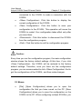
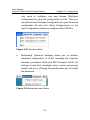
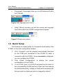
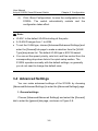
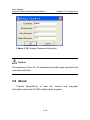
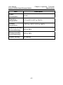
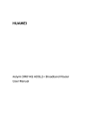
1
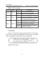
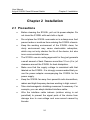
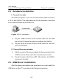
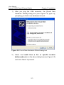
Aolynk S1505L Smart Ethernet Switch
User Manual
Manual Version:
T2-UM-20070710-3.05
Huawei Technologies Proprietary
Huawei Technologies Co., Ltd. provides customers with comprehensive technical
support and service. For any assistance, please contact our local office or company
headquarters.
Huawei Technologies Co., Ltd.
Address:
310 Liuhe Road, Zhijiang Science Park,
Hangzhou Zhejiang Province, P. R. China
Postal Code: 310053
Website:
http://www.h3c.com
Email:
[email protected]
Copyright © Huawei Technologies Co., Ltd. 2006-2007. All rights
reserved.
No part of this document may be reproduced or transmitted in any form or by any
means without prior written consent of Huawei Technologies Co., Ltd.
Trademarks and Permissions
and other Huawei trademarks are trademarks of Huawei Technologies Co.,
Ltd.
All other trademarks and trade names mentioned in this document are the property of
their respective holders.
Notice
The information in this document is subject to change without notice. Every effort has
been made in the preparation of this document to ensure accuracy of the contents,
but all statements, information, and recommendations in this document do not
constitute the warranty of any kind, express or implied.
Huawei Technologies Proprietary
CE
This equipment complies with the following European Directives: 89/336/EEC
(electromagnetic compatibility), 73/23/EEC (low voltage).
Huawei Technologies Proprietary
About This Manual
Purpose
This document is used to guide you through installing, configuring,
maintaining and managing this product. Please read it carefully before
your operation.
Intended Audience
This document is intended for network administrators who know well
of the basic network knowledge and network terms.
Organization
This document is organized as follows:
Chapter
Content
1 Product Overview
This chapter describes the appearance
and features of the Aolynk S1505L Smart
Ethernet Switch.
2 Installation
This chapter describes the precautions and
steps to install the Aolynk S1505L Smart
Ethernet Switch.
3 Configuration
This chapter describes the interfaces of the
configuration program and how to
configure the Aolynk S1505L Smart
Ethernet Switch.
Chapter
4
Appendix
Technical
Specifications
Content
–
This chapter describes the technical
specifications of the Aolynk S1505L Smart
Ethernet Switch.
Conventions
The manual uses the following conventions:
I. GUI conventions
Convention
Description
<>
Button names are inside angle brackets.
For example, click <OK>.
[]
Window names, menu items, data table
and field names are inside square
brackets. For example, pop up the [New
User] window.
/
Multi-level menus are separated by forward
slashes. For example, [File/Create/Folder].
II. Symbols
Convention
Description
Caution
Means reader be careful. Improper
operation may cause data loss or damage
to equipment.
Note
Means a complementary description.
User Manual
Aolynk S1505L Smart Ethernet Switch
Table of Contents
Table of Contents
Chapter 1 Product Overview ........................................................1-1
1.1 Appearance........................................................................1-1
1.2 Features .............................................................................1-3
Chapter 2 Installation ....................................................................2-1
2.1 Precautions ........................................................................2-1
2.2 Hardware Installation .........................................................2-2
2.3 USB Driver Installation .......................................................2-2
Chapter 3 Configuration................................................................3-1
3.1 Login ..................................................................................3-1
3.2 Main Configuration Window ...............................................3-2
3.3 Quick Setup........................................................................3-7
3.4 Advanced Settings .............................................................3-8
3.5 Changing Password .........................................................3-18
3.6 About................................................................................3-19
Chapter 4 Appendix – Technical Specifications ........................4-1
i
User Manual
Aolynk S1505L Smart Ethernet Switch
Chapter 1 Product Overview
Chapter 1 Product Overview
Aolynk S1505L Smart Ethernet Switch (hereinafter referred to as
the S1505L) is oriented to small and medium-sized enterprise users
and SOHO users for IPTV application. It provides five autosensing
10/100Base-TX Ethernet ports:
z
Uplink port: Connected to carrier network
z
VoIP port: Connected to IP phone
z
TV port: Connected to IPTV set-top box
z
PC port: Connected to PC
z
EXP port: Expansion port (which can be used as the console
port)
1.1 Appearance
I. Front panel
Figure 1-1 shows the LEDs on the front panel of the S1505L: a
power LED, pairs of speed and Link/Act LEDs, with each pair
corresponding to one Ethernet port.
Figure 1-1 Front panel
1-1
User Manual
Aolynk S1505L Smart Ethernet Switch
Chapter 1 Product Overview
Table 1-1 LED description
LED
Power
Speed
State
Label
State
Description
Green
The S1505L is powered on.
OFF
The S1505L is powered off.
Green
The port is operating at 100 Mbps.
OFF
The port is operating at 10 Mbps,
or no Ethernet link is present.
Green
An Ethernet link is established.
OFF
No Ethernet link is present.
Blinking
green
Data is being transmitted and/or
received on the port.
Power
Speed
Link/Act
II. Rear panel
Figure 1-2 shows the rear panel of the S1505L. On this panel,
there are five autosensing 10/100Base-TX Ethernet ports, one Reset
button (unavailable for the S1505L), and one power jack.
Figure 1-2 Rear panel
1-2
User Manual
Aolynk S1505L Smart Ethernet Switch
Chapter 1 Product Overview
1.2 Features
Table 1-2 Feature description
Feature
VLAN (virtual
local area
network)
Port
Description
IEEE 802.1Q-compliant VLAN
Port-based VLAN
16 VLANs at most
Broadcast storm control
Flow control, compliant with 802.3x
MAC (media
access control)
address table
Address learning, with default address aging
time of 300 seconds
Management
Management via configuration program
Maximum MAC address entries: 2 K
802.1p priority queue
QoS (quality of
service)
Four priority queues per port
Rate limit on each port
1-3
User Manual
Aolynk S1505L Smart Ethernet Switch
Chapter 2 Installation
Chapter 2 Installation
2.1 Precautions
z
Before cleaning the S1505L, pull out its power adapter. Do
not clean the S1505L with wet cloth or liquid.
z
Do not place the S1505L near water or in a damp area. And
prevent water or moisture from entering the S1505L chassis.
z
Keep the working environment of the S1505L clean, for
dusty environment may cause electrostatic adsorption,
which may not only shorten the life of the device, but also
incur communication failures.
z
The S1505L use air cooling approach for they just generate
a small amount of heat. Reserve more than 10 cm (4 in.) of
clearance around the S1505L for heat dissipation.
z
Make sure that the supply voltage is consistent with that
labeled on the S1505L. It is strongly recommended that you
use the power adapter accompanying the S1505L for the
power supply.
z
Keep the S1505L far away from powerful radio transmitters,
radars and high-frequency devices working in high current.
z
Take electromagnetic shielding measures if necessary. For
example, you can adopt shielded interface cable.
z
Wire the interface cable indoors (outdoor wiring is not
permitted) to prevent the signal ports of the device from
damage due to over-voltage and over-current caused by
thunder.
2-1
User Manual
Aolynk S1505L Smart Ethernet Switch
Chapter 2 Installation
2.2 Hardware Installation
I. Connect the cable
As shown in Figure 2-1, you can use the console cable to connect
a PC to the S1505L. This cable takes an RJ-45 connector at one end
and a USB connector at the other end.
Figure 2-1 PC connection
1)
Plug the USB connector of the console cable into the USB
port of the PC that will be used to configure the S1505L.
2)
Plug the RJ-45 connector of the console cable into the EXP
port of the S1505L.
II. Connect the power adapter
1)
Attach one end of the power adapter to the power jack of the
S1505L and the other end to the external power socket.
2)
Check the state of the Power LED. ON indicates the S1505L
is powered normally.
2.3 USB Driver Installation
After the above connections are completed, you must install the
USB driver on the PC according to the following procedure:
2-2
User Manual
Aolynk S1505L Smart Ethernet Switch
1)
Chapter 2 Installation
After you plug the USB connector, the [Found New
Hardware Wizard] dialog box (see Figure 2-2) pops up,
prompting you that a new hardware is found.
Figure 2-2 Found New Hardware Wizard dialog box
2)
Select the Install from a list or specific location
[Advanced] option in the above dialog box (see Figure 2-2)
and click <Next> to proceed.
2-3
User Manual
Aolynk S1505L Smart Ethernet Switch
Chapter 2 Installation
Figure 2-3 Select the locations for searching the driver
3)
Insert the driver CD-ROM into the drive of your PC. Select
the Search removable media [floppy, CD-ROM…] check
box and click <Next>.
4)
Click <Continue Anyway> to ignore the Microsoft logo test
and start the installation. After the installation, the
[Completing the Found New Hardware Wizard] dialog box
(see Figure 2-4) pops up.
2-4
User Manual
Aolynk S1505L Smart Ethernet Switch
Chapter 2 Installation
Figure 2-4 Complete the installation
5)
Click <Finish> to complete the installation.
2-5
User Manual
Aolynk S1505L Smart Ethernet Switch
Chapter 3 Configuration
Chapter 3 Configuration
You can use the configuration program in the CD-ROM
accompanying the S1505L to configure and manage the S1505L.
After the hardware connection and USB driver installation, you can run
the configuration program on the PC and make a connection to the
S1505L for further operation.
3.1 Login
Run the configuration program and the [Login] dialog box (see
Figure 3-1) pops up. Type in the password (admin by default, which
you can change after logging in) in the [Password] field. Click <OK> to
enter the main configuration window of the S1505L.
Figure 3-1 Login dialog box
3-1
User Manual
Aolynk S1505L Smart Ethernet Switch
Chapter 3 Configuration
Note:
The default user name Admin is unchangeable, but you can change
the password after logging into the configuration page. Refer to
section 3.5 “Changing Password” for details.
3.2 Main Configuration Window
Figure 3-2 Main configuration window (in disconnected status)
After you log into the S1505L configuration page, click <Connect>
and the program automatically searches for the COM port that is
connected to the S1505L to make a connection with the S1505L.
Once the connection is set up, the [Status] field displays Connected
3-2
User Manual
Aolynk S1505L Smart Ethernet Switch
Chapter 3 Configuration
on the page and the exact port is displayed in the [COM Port] field (see
Figure 3-3).
Figure 3-3 Main configuration window (in connected status)
I. Quick setup section
The quick setup section allows you to set the S1505L quickly. In
this section, you can set the speed, priority, rate limit, flow control, and
VLAN for each port. The Port column of this section indicates the
relationship between the port names and their sequence numbers. To
perform the advanced VLAN configuration, you must have knowledge
about this.
z
Speed/Duplex: Select the speed for the port from the
drop-down list. Six options are available: Auto (default), 100
Full, 100 Half, 10 Full, 10 Half, Disabled. When Auto is
3-3
User Manual
Aolynk S1505L Smart Ethernet Switch
Chapter 3 Configuration
selected, the switch automatically negotiates an operating
speed and duplex mode with the peer port.
z
Priority: Four options are available from the drop-down list:
Highest, High, Low and Lowest. You cannot configure the
priority for the Uplink port. By default, the priorities for the
VoIP, TV, PC, and EXP ports are arranged in descending
order, that is, from the Highest (VoIP) to the Lowest (EXP).
z
Rate Limit: Port-based rate limit. This feature controls the
packet receiving and transmitting rates on the port and is
disabled by default. To enable the feature, choose
[Advance/Advanced Settings] to enter the [Advanced
Settings] dialog box and make configurations on the
[General] tab page. For details, refer to section 3.4 "I.
General settings". Once enabled, nine options are available
in the drop-down list: 64K, 128K, 256K, 512K, 1M, 2M, 4M,
8M and Disabled.
z
Flow Control: This feature controls the packets received and
sent on each port to prevent packet loss and is commonly
used for congestion management. There are two available
options: Enabled and Disabled (default).
z
VLAN: You can type in the VLAN ID to create a VLAN
containing both this port and the Uplink port. By default, all
the ports have the VLAN ID of 1 and belong to the same
VLAN, and the Uplink port is tagged.
II. Buttons
z
<Connect>: Click this button to make the program
automatically search for the communication port that is
3-4
User Manual
Aolynk S1505L Smart Ethernet Switch
Chapter 3 Configuration
connected to the S1505L to make a connection with the
S1505L.
z
<Show Configuration>: Click this button to display the
current configuration of the S1505L.
z
<Save Configuration>: Click this button to save your
configuration to the S1505L. This operation will cause the
S1505L to restart. Your configuration takes effect only after
you save them.
z
<Disconnect>: Click this button to disconnect the S1505L
from the configuration program.
z
<Exit>: Click this button to exit the configuration program.
Caution:
Every time you run the configuration program, the main configuration
window shows the factory default settings. At this time, if you click
<Save Configuration>, the S1505L will be restored to the factory
default settings. Therefore, once you have run the configuration
program, you are recommended to click <Show Configuration> first to
get the configurations of the S1505L, and then make changes.
III. Menus
z
[File]: [Open Configuration] allows you to open the
configuration file that you have saved on the PC. [Save
Configuration] allows you to save the configuration on the
S1505L to the PC. When configuring multiple S1505Ls, you
3-5
User Manual
Aolynk S1505L Smart Ethernet Switch
Chapter 3 Configuration
only need to configure one and choose [File/Save
Configuration] to save the configuration to a file. Then you
can just choose [File/Open Configuration] to open the saved
configuration file and click <Save Configuration> on the
main configuration window to configure other S1505Ls.
Figure 3-4 File menu items
z
[Advanced]: [Advance Settings] allows you to perform
advanced configuration of VLAN, including the selection
between port-based VLAN and 802.1Q-based VLAN, the
settings of rate limit, broadcast storm control and priority
weight, and so on. [Change Password] allows you to modify
the password.
Figure 3-5 Advanced menu items
3-6
User Manual
Aolynk S1505L Smart Ethernet Switch
z
Chapter 3 Configuration
[Language]: [Language] allows you to shift between English
and Chinese.
Figure 3-6 Language menu items
z
[Help]: [About] provides you with the version and copyright
information about the S1505L configuration program.
Figure 3-7 Help menu items
3.3 Quick Setup
The following four steps guide you through the quick setup of the
S1505L on the main configuration window:
1)
Click <Connect> and the program automatically searches
for the COM port connected to the S1505L to make a
connection with the S1505L. Once connected is displayed,
you can configure the S1505L.
2)
Click
<Show
Configuration>
to
display
the
current
configurations of the S1505L.
3)
To set VLAN, type in a VLAN ID assigned by the carrier in
the corresponding [VLAN] text box of each port according to
the actual networking, creating a VLAN which contains both
this port and the Uplink port which is tagged by default.
3-7
User Manual
Aolynk S1505L Smart Ethernet Switch
4)
Chapter 3 Configuration
Click <Save Configuration> to save the configuration to the
S1505L. The switch automatically restarts and the
configuration takes effect.
Note:
z
VLAN 1 is the default VLAN including all the ports.
z
A VLAN ID ranges from 1 to 4094.
z
To set the VLAN type, choose [Advanced/Advanced Settings] and
enter the [General] tab page to make a selection from the [VLAN
Type] drop-down list. The default VLAN type is 802.1Q-based.
z
You can set the speed, priority, rate limit, and flow control from the
corresponding drop-down lists in the quick setup section. The
S1505L operates normally with the default settings, so generally
you do not need to change the default ones.
3.4 Advanced Settings
You can make advanced settings of the S1505L by choosing
[Advanced/Advanced Settings] to enter the [Advanced Settings] page.
I. General settings
Choose [Advanced/Advanced Settings] and select the [General]
tab to enter the [general] tab page, as shown in Figure 3-8.
3-8
User Manual
Aolynk S1505L Smart Ethernet Switch
Chapter 3 Configuration
Figure 3-8 General tab page
z
Broadcast Storm: Limit the broadcast traffic on the port.
When the broadcast traffic exceeds the customer-defined
value, the system drops the broadcast packets to reduce the
broadcast ratio to a reasonable value. This efficiently
controls the broadcast storm and ensures the network
services. To enable the function, select the [Enable
Broadcast Control] check box. Four options are available,
5%, 10%, 20%, or 100%, from the [Ratio] drop-down list.
100% means broadcast storm is not controlled. This feature
is disabled by default.
z
MAC Aging Time: Four options are available, 1 sec., 18 sec.,
75 sec., and 300 sec. (default).
3-9
User Manual
Aolynk S1505L Smart Ethernet Switch
z
Chapter 3 Configuration
VLAN Type: Two options are available, 802.1Q-based VLAN
(default) and Port-based VLAN.
z
IGMP Snooping: A multicast control mechanism running on
Layer 2 switch. It is used for multicast group management
and control. Based on source address learning, the switch
learns the MAC address. When the layer 2 switch receives
multicast packets and cannot judge whether they are
multicast or not, the switch processes them as broadcast.
Thus the multicast takes no effect. However, when IGMP
Snooping runs, multicast packet is not broadcast on Layer 2.
By default, this feature is disabled.
z
Rate Limit Options: Two options are available, Enabled and
Disabled (default). If you enable rate limit, you can select the
Ingress, Egress, or both option from the [Control Type]
drop-down list.
z
Soft Reset: Click <Reset Switch> and the S1505L restarts.
Note that you should save current configuration to the
S1505L before clicking this button; otherwise, the changes
you make will not take effect.
II. VLAN priority mapping
Choose [Advanced/Advanced Settings] and select the [VLAN
Priority Mapping] tab to enter the [VLAN Priority Mapping] tab page, as
shown in Figure 3-9. In this page, you can map the priorities of VLAN
tag to corresponding priority queues.
The S1505L supports four priority queues for each port, that is,
highest, high, low, and lowest queues. It places an Ethernet frame into
a corresponding output queue based on the priority of the VLAN tag in
the frame. The frames in the queue with higher priority will be sent in
3-10
User Manual
Aolynk S1505L Smart Ethernet Switch
Chapter 3 Configuration
precedence. By default, the mapping is as follows: 0 and 1 are
mapped to the lowest queue, 2 and 3 to low, 4 and 5 to high, 6 and 7 to
highest.
Figure 3-9 VLAN Priority Mapping tab page
III. Priority weight
Choose [Advanced/Advanced Settings] and select the [Priority
Weight] tab to enter the [Priority Weight] tab page, as shown in Figure
3-10. In this page, you can configure the weights of priority queues.
The S1505L supports four priority queues for each port and
performs polling based on the priority weights of the queues. The
queues can be set to different weights; so that different service
qualities are provided for different requirements. By default, the
3-11
User Manual
Aolynk S1505L Smart Ethernet Switch
Chapter 3 Configuration
weights of the four priority queues are in the ratio of 1:2:4:8. The
weight of the lowest queue is 1, which cannot be changed, and
weights of other queues ranges from 1 to 15.
Figure 3-10 Priority Weight tab page
IV. Advanced port settings
Choose
[Advanced/Advanced
Settings]
and
select
the
[Advanced Port Settings] tab to enter the [Advanced Port Settings] tab
page, as shown in Figure 3-11. In this page, you can perform more
configurations on the ports of the S1505L.
z
Ingress Filter: The S1505L checks the VLAN ID of the
packets on the ingress port. For instance, if you enable the
feature by selecting the [Ingress Filter] check box for port 2
which does not belong to VLAN 100, the switch drops the
3-12
User Manual
Aolynk S1505L Smart Ethernet Switch
Chapter 3 Configuration
packets with VLAN ID of 100 arriving at port 2. By default,
ingress filter is enabled.
z
PVID: Used to display and configure the PVID of each port.
By default, the PVIDs displayed here are the same as the
VLAN IDs on the main configuration window.
Figure 3-11 Advanced Port Settings tab page
V. VLAN
Choose [Advanced/Advanced Settings] and click [VLAN] to enter
the [VLAN] tab page, as shown in Figure 3-12.
The VLAN management involves creating, editing and deleting
VLAN. The management of 802.1Q-based VLAN differs from that of
port-based VLAN. Therefore, you should select the required VLAN
3-13
User Manual
Aolynk S1505L Smart Ethernet Switch
Chapter 3 Configuration
type on the [General] tab page before configuring the VLANs. By
default, this type is 802.1Q-based VLAN.
1)
802.1Q-based VLAN
Section 3.3
“Quick Setup” describes how to create an
802.1Q-based VLAN: Type in the VLAN ID in the corresponding VLAN
text box of a port on the quick setup section of the main configuration
window. For instance, after you have created VLAN 10, VLAN 20,
VLAN 30, and VLAN 40 for the VoIP, TV, PC, EXP ports respectively,
these VLANs are shown in Figure 3-12. The information on the [VLAN]
tab page represents the configuration you have made on the main
configuration window.
Figure 3-12 802.1Q-based VLAN configuration
3-14
User Manual
Aolynk S1505L Smart Ethernet Switch
z
Chapter 3 Configuration
Create a VLAN
To create a VLAN, click <New> on the [VLAN] tab page (see
Figure 3-12) to enter the [VLAN Member Settings] dialog box (see
Figure 3-13).
Figure 3-13 Create a VLAN
Type in a VLAN ID in the corresponding text box. Select any
[Member] check box to add the corresponding port to this VLAN, and
then select the Tagged or Untagged option from the corresponding
drop-down list.
z
Edit a VLAN
3-15
User Manual
Aolynk S1505L Smart Ethernet Switch
Chapter 3 Configuration
To edit an existing VLAN, click <Edit> on the [VLAN] tab page
(see Figure 3-12) to enter the [VLAN Member Settings] dialog box
(see Figure 3-14).
Figure 3-14 Edit a VLAN
In this dialog box, you can remove or add members of the VLAN
and change the tag attribute of each port, but you cannot change the
VLAN ID.
z
Delete a VLAN
To delete a VLAN, select the [Member] box corresponding to the
VLAN in the [Advanced Settings] dialog box (see Figure 3-12), click
<Delete>, and confirm. Then the VLAN is deleted.
3-16
User Manual
Aolynk S1505L Smart Ethernet Switch
Chapter 3 Configuration
Caution:
VLAN 1 is the default VLAN, which includes all the ports and cannot
be deleted.
2)
Port-based VLAN
You can create port-based VLAN as needed. First you need to
set the VLAN type to port-based VLAN in Figure 3-8. Then choose
[Advanced/Advanced Settings] and select the [VLAN] tab to enter the
corresponding dialog box (see Figure 3-15).
Figure 3-15 Port-based VLAN configuration
3-17
User Manual
Aolynk S1505L Smart Ethernet Switch
Chapter 3 Configuration
By default, VLAN 1 includes all the ports. You can only create a
VLAN that includes port 1 and port 5. Click <New> and you may begin
your creation. If you need to remove or add some ports in the VLAN,
click <Edit>. You can click <Delete> to delete a VLAN, but when there
is only one VLAN left, the last VLAN becomes the default VLAN and
you cannot delete it.
Caution:
Changing the VLAN type may cause clearing all the VLAN settings
before.
Port 1 (Uplink) and port 5 (EXP) can be added to multiple VLANs,
While other ports can only be added to a VLAN.
3.5 Changing Password
Choose [Advance/Change Password] to enter the [Change
Password] dialog box, as shown in the following figure. To change the
password, type in the old password, a new password, and the new
password again. Then click <OK>.
3-18
User Manual
Aolynk S1505L Smart Ethernet Switch
Chapter 3 Configuration
Figure 3-16 Change Password dialog box
Caution:
The password is from 4 to 12 characters in length (case sensitive) and
cannot be left blank.
3.6 About
Choose [Help/About] to view the version and copyright
information about the S1505L configuration program.
3-19
User Manual
Aolynk S1505L Smart Ethernet Switch
Chapter 4 Appendix – Technical
Specifications
Chapter 4 Appendix – Technical
Specifications
Table 4-1 Technical specifications
Item
Ports
Description
Five autosensing 10/100Base-TX Ethernet
ports
RJ-45 connector
Compliant with IEEE 802.3, IEEE 802.3u,
and IEEE 802.3x
Port attributes
10/100 Mbps transmission rate
Half duplex, full duplex and auto-negotiation
Auto-MDI/MDIX
10Base-T:
Cable
Category 3/4/5 shielded twisted pair (STP)
with the maximum transmission distance of
100 m (328 ft)
100Base-TX:
Category 5 STP with the maximum
transmission distance of 100 m (328 ft)
Physical
dimensions
34 × 150 × 110 mm (1.3 × 5.9 × 4.3 in)
(H × W × D)
Weight
300 g (10.6 oz)
Input voltage
12 VDC
4-1
User Manual
Aolynk S1505L Smart Ethernet Switch
Item
Chapter 4 Appendix – Technical
Specifications
Description
Power
consumption
4.5 W
Operating
temperature
0°C to 40°C (32°F to 104°F)
Storage
temperature
–10°C to +70°C (14°F to 158°F)
Operating humidity
(noncondensing)
20% to 85%
Storage humidity
(noncondensing)
10% to 90%
System cooling
Air cooling
4-2