1
Contents
Programming HP VXI Instruments
Common Commands and the Status System
Edition 1
Chapter 1
Introduction .................................................................................................................... 5
Chapter 2
Programming the Status System .................................................................................. 7
About this Chapter ........................................................................................................ 7
General Status Register Model ..................................................................................... 7
Condition Register ................................................................................................. 8
Transition Filter ..................................................................................................... 8
Event Register ....................................................................................................... 8
Enable Register ..................................................................................................... 8
An Example Sequence .......................................................................................... 8
Required Status Groups .............................................................................................. 10
Status Byte ........................................................................................................... 11
Standard Event Group ......................................................................................... 12
Standard Operation Status Group ........................................................................ 13
Questionable Data Group .................................................................................... 14
Status System Programming Examples ...................................................................... 15
Handling SRQs .................................................................................................... 15
Using MAV to Determine When Data is Available ............................................ 15
Example Program ......................................................................................... 16
Using a Service Request to Detect Errors ........................................................... 18
Example Program ......................................................................................... 19
Chapter 3
Command Reference ................................................................................................... 23
About this Chapter ...................................................................................................... 23
STATus ....................................................................................................................... 24
Subsystem Syntax ......................................................................................... 24
:OPERation :CONDition? ................................................................................... 24
Comments ..................................................................................................... 24
Example ........................................................................................................ 24
:OPERation:ENABle ........................................................................................... 24
Parameters ..................................................................................................... 24
Comments ..................................................................................................... 24
Example ........................................................................................................ 24
:OPERation:ENABle? ......................................................................................... 25
Comments ..................................................................................................... 25
Example ........................................................................................................ 25
:OPERation[:EVENt]? ........................................................................................ 25
Comments ..................................................................................................... 25
Example ........................................................................................................ 25
:PRESet ............................................................................................................... 25
Example ........................................................................................................ 25
:QUEStionable :CONDition? .............................................................................. 25
Comments ..................................................................................................... 26
Contents
1
Example ........................................................................................................ 26
:QUEStionable:ENABle ...................................................................................... 26
Parameters ..................................................................................................... 26
Comments ..................................................................................................... 26
Example ........................................................................................................ 26
:QUEStionable:ENABle? .................................................................................... 26
Comments ..................................................................................................... 26
Example ........................................................................................................ 26
:QUEStionable[:EVENt]? ................................................................................... 26
Comments ..................................................................................................... 26
Example ........................................................................................................ 27
Common Command Reference................................................................................... 28
*CLS .................................................................................................................... 28
*DMC <name_string>, <command_block> ....................................................... 29
*EMC <enable> .................................................................................................. 29
*EMC? ................................................................................................................ 29
*ESE <mask> ...................................................................................................... 29
Example ........................................................................................................ 29
*ESE? .................................................................................................................. 29
Example ........................................................................................................ 29
*ESR? .................................................................................................................. 29
Example ........................................................................................................ 30
*GMC? <name_string> ....................................................................................... 30
Example ........................................................................................................ 30
*IDN? .................................................................................................................. 30
Example ........................................................................................................ 30
*LMC? ................................................................................................................ 30
*LRN? ................................................................................................................. 30
*OPC ................................................................................................................... 31
*OPC? ................................................................................................................. 31
*PMC .................................................................................................................. 31
*RMC <name_string> ......................................................................................... 31
Example ........................................................................................................ 31
*RST .................................................................................................................... 31
*SRE <mask> ...................................................................................................... 32
Example ........................................................................................................ 32
*SRE? .................................................................................................................. 32
Example ........................................................................................................ 32
*STB? .................................................................................................................. 32
Comments ..................................................................................................... 32
Example ........................................................................................................ 32
*TST? .................................................................................................................. 32
Example ........................................................................................................ 32
*WAI ................................................................................................................... 33
2
Contents
This document contains proprietary information which is protected by copyright. All rights are reserved.
No part of this document may be photocopied, reproduced, or translated to another language without the
prior written consent of Hewlett-Packard Company.
E2090-90021
Notice
The information contained in this document is subject to change without notice.
Hewlett-Packard Company (HP) shall not be liable for any errors contained in this document. HP makes no
warranties of any kind with regard to this document, whether express or implied. HP specifically disclaims
the implied warranties of merchantability and fitness for a particular purpose. HP shall not be liable for any
direct, indirect, special, incidental, or consequential damages, whether based on contract, tort, or any other
legal theory, in connection with the furnishing of this document or the use of the information in this document.
Warranty Information
A copy of the specific warranty terms applicable to your Hewlett-Packard product and replacement parts
can be obtained from your local Sales and Service Office.
Restricted Rights Legend
Use, duplication or disclosure by the U.S. Government is subject to restrictions as set forth in subparagraph
(c)(1)(ii) of the Rights in Technical Data and Computer Software clause of DFARS 252.227-7013.
Use of this manual and magnetic media supplied for this product are restricted. Additional copies of the
software can be made for security and backup purposes only. Resale of the software in its present form or
with alterations is expressly prohibited.
Copyright © Hewlett-Packard Company 1994
Printing History
This is the first edition of “Programming HP VXI Instruments”
September 1994; First Edition
3
This Page Intentionally Left Blank
4
Chapter 1
Introduction
This document describes the common commands and the status system used
by VXI instruments. The status system is a group of registers that can be
used to monitor events, such as when an error occurs or when a reading is
available from a specified instrument in your VXI mainframe. Use the SCPI
status system commands and IEEE 488.2 common commands described in
Chapter 3 of this document to program the status system.
The common commands are used to read and configure the status byte and
standard event group registers, while the status commands are used to
configure the standard operation status group and questionable data status
group registers. See the individual VXI instrument manuals to determine
how a specific instrument uses the operation status group and the
questionable data status group. If status system commands are not
documented, that instrument does not use the registers.
Other common commands are used for general functionality, macros, and
synchronization.
Note
Chapter 1
This document should be placed with your other VXI instrumentation
documentation.
Introduction
5
Notes:
6 Introduction
Chapter 1
Chapter 2
Programming the Status System
About this Chapter
This chapter discusses the structure of the status system used in SCPI
instruments and explains how to program status registers. An important
feature of SCPI instruments is that they all implement status registers in the
same way. The status system is explained in the following sections:
• General Status Register Model
This section explains the way that status registers are structured in
SCPI instruments. It also contains an example of how bits in the
various registers change with different input conditions.
• Required Status Groups
This section describes the minimum required status registers present in
SCPI instruments. These status registers cover the most frequently
used functions.
General Status Register Model
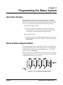
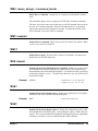
The generalized status register model shown in Figure 2-1 is the building
block of the SCPI status system. This model consists of a condition register,
transition filter, an event register, and an enable register. A set of these
registers is called a status group.
When a status group is implemented in an instrument, it always contains all
of the component registers. However, there is not always a corresponding
command to read or write to every register.
Figure 2-1. Generalized Status Register Model
Chapter 2
Programming the Status System
7
Condition Register
The condition register continuously monitors the hardware and firmware
status of the instrument. There is no latching or buffering for this register;
it is updated in real time. Condition registers are read-only.0
If there is no command to read a particular condition register, it is simply
invisible to you.
Transition Filter
The transition filter specifies which types of bit state changes in the
condition register will set corresponding bits in the event register.
Transition filter bits may be set for positive transitions (PTR), negative
transitions (NTR), or both. Positive means a condition bit changes from
0 to 1. Negative means a condition bit changes from 1 to 0. Transition filters
are read-write. Transition filters are unaffected by *CLS (clear status) or
queries. They are set to instrument-dependent values at power
on and after *RST (reset).
If there are no commands to access a particular transition filter, it has a
fixed setting. This setting is specified in the instrument’s programming
guide or command dictionary. Most of our VXI instruments assign the
transition filter to detect positive transitions only.
Event Register
The event register latches transition events from the condition register as
specified by the transition filter. Bits in the event register are latched, and,
once set, they remain set until cleared by a query or *CLS (clear status).
There is no buffering; so while an event bit is set, subsequent events
corresponding to that bit are ignored. Event registers are read-only.
Enable Register
The enable register specifies which bits in the event register can generate a
summary bit. The instrument logically ANDs corresponding bits in the
event and enable registers, and ORs all the resulting bits to obtain a summary
bit. Summary bits are, in turn, recorded in another register, often the Status
Byte. Enable registers are read-write. Enable registers are not affected by
*CLS (clear status). Querying enable registers does not affect them. There
is always a command to read and write to the enable register of a particular
status group.
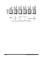
An Example
Sequence
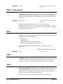
Figure 2-2 illustrates the response of a single bit position in a typical status
group for various settings. The changing state of the condition in question
is shown at the bottom of the figure. A small binary table shows the state of
the chosen bit in each status register at the selected times T1-T5.
8 Programming the Status System
Chapter 2
Figure 2-2. Typical Status Bit Changes in a Status Register
Chapter 2
Programming the Status System
9
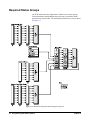
Required Status Groups
All SCPI instruments must implement a minimum set of status groups.
Some instruments contain additional status groups, consistent with the
general status register model. The minimum required status system is shown
in Figure 2-3.
Figure 2-3. Minimum Required Status Register System
10
Programming the Status System
Chapter 2
The Standard Operation Status and Questionable Data groups are 16 bits
wide, while Status Byte and Standard Event groups are only 8 bits wide. In
all 16 bit groups, the most significant bit (bit 15) is not used. Bit 15 always
returns a zero. The commands that set and query bits in the status registers
all use decimal integers. For example, you send *ESE 4 to set bit 2 of the
Standard Event enable register. Similarly, a response of "8" to the query
*ESE? indicates that bit 3 is set. The remainder of this chapter explains each
status group in detail.
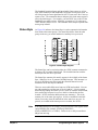
Status Byte
As Figure 2-4 indicates, the Status Byte is used to summarize information
from all the other status groups. The Status Byte differs from the other
groups in the way you read it and how its summary bit is processed.
Figure 2-4. Status Byte Register
The Status Byte can be read using either the *STB? common command or
by doing a SICL ireadstb function call. The ireadstb function reads the
status byte from the device specified.
The Status Byte summary bit actually appears in bit 6 (RQS) of the Status
Byte. When bit 6 is set, it generates an SRQ interrupt. This interrupt is a
low-level HP-IB message that signals the controller that at least one
instrument on the bus requires attention.
There are some subtle differences between *STB? and ireadstb. You can
use either method to read the state of bits 0-5 and bit 7. Bit 6 is treated
differently depending on whether you use *STB? or ireadstb. With ireadstb,
bit 6 returns RQS (request for service) which is cleared after the first
ireadstb. *STB? returns the MSS (master state summary). This is the
summary bit of the status byte register. It’s like a condition bit and will
return to zero only when all enabled bits in the status byte are zero. In
general, use ireadstb inside interrupt service routines, not *STB?.
Note
Chapter 2
In an SRQ interrupt service routine, you must clear the event register which
caused the SRQ (for example, STATus:QUES:EVEN?,
STATus:OPER:EVEN?, or *ESR?). Failure to do so will prevent future
SRQs from arriving.
Programming the Status System
11
The meaning of each bit in the Status Byte is explained in the following
table.
Table 2-1. Status Byte Bit Definitions
Bit
Name
Description
0
Instrument dependent
1
Instrument dependent
2
Instrument dependent
3
QUE
Summary bit from Questionable Data
4
MAV
Messages available in Output Queue
5
ESB
Summary bit from Standard Event
6
RQS
Service request
7
OPR
Summary bit from Standard Operation
Status
Example commands using the Status Byte and Status Byte enable registers:
*SRE 16
Generate an SRQ interrupt when messages are available.
*SRE?
Find out what events are enabled to generate SRQ
interrupts.
*STB?
Standard Event
Group
Read and clear the Status Byte event register.
The Standard Event status group is frequently used and is one of the
simplest. The unique aspect of Standard Event is that you program it using
common commands, while you program all other status groups through the
STATus subsystem. Standard Event consists of only two registers: the
Standard Event event register and the Standard Event enable register. Figure
2-5 illustrates the structure of Standard Event.
Figure 2-5. Standard Event Status Group
12
Programming the Status System
Chapter 2
Example commands using Standard Event registers:
*ESE 48 Generate a summary bit on execution or command errors.
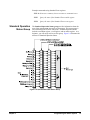
Standard Operation
Status Group
*ESE?
Query the state of the Standard Event enable register.
*ESR?
Query the state of the Standard Event event register.
The Standard Operation Status group provides information about the
state of the measurement systems in an instrument. This status group is
accessed through the STATus subsystem. Standard Operation Status
includes a condition register, event register, and an enable register. As a
beginner, you will rarely need to use this group. Figure 2-6 illustrates the
structure of Standard Operation Status.
Figure 2-6. Questionable Data Status Group
Chapter 2
Programming the Status System
13
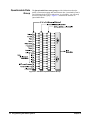
Questionable Data
Group
The Questionable Data status group provides information about the
quality of instrument output and measurement data. Questionable Data is
accessed through the STATus subsystem. As a beginner, you will rarely
need to use this status group. Figure 2-7 illustrates the structure of
Questionable Data.
Figure 2-7. Standard Operation Status Group
14
Programming the Status System
Chapter 2
Status System Programming Examples
This section contains two example programs that use the status system and
common commands to monitor when data is available from an instrument
and when an error has occurred. Both programming examples are written in
C and use the Standard Instrument Control Library (SICL) for I/O
operations. The example programs use SCPI (Standard Commands for
Programmable Instruments) commands to communicate with the status
system. Thus, the instruments must either be message-based or have a SCPI
interpreter, such as an HP E1405/06 Command Module or the SICL iscpi
interface.
Handling SRQs
The following is a general procedure for handling SRQs:
• Define the SRQ handler to do the following:
-- Read the Status Byte using ireadstb. ireadstb returns the RQS
(request for service) bit in bit 6 of the status byte. After issuing a
ireadstb, RQS is cleared indicating that the Service Request is being
acknowledged. A new SRQ will not be issued unless RQS is
cleared. Using *STB? will return the Master State Summary in bit 6
and does not affect RQS, therefore this should not be used in a SRQ
handler.
-- Check the status byte to determine which status group(s) requires
service.
-- For each status group that requires service, read the event register of
that status group to determine what caused the SRQ to be generated.
It is necessary to clear the event register so that if a new event
occurs a new SRQ will be generated.
-- Take some action after determining which event caused the SRQ.
The action taken is determined by evaluating the contents of the
event register.
• Enable SRQ Handler in SICL with ionsrq.
• Make sure that all the Enable Masks in all the status enable registers
are set to the proper values to propagate the summary bit(s) to the
status byte. An SRQ is only generated if the MSS (Master State
Summary) bit in the status byte is set.
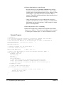
Using MAV to
Determine When
Data is Available
The following example program sets up an SRQ handler to be called when
there is data in the output queue. The program then prompts for SCPI
commands. If the SCPI command results in data in the output queue (such
as a query command), then the SRQ handler is called and the data is printed.
The following summarizes the procedure used:
Chapter 2
Programming the Status System
15
• Define an SRQ handler to do the following:
-- Read the Status Byte using ireadstb. ireadstb returns the RQS
(request for service) bit in bit 6 of the status byte. After issuing a
ireadstb, RQS is cleared indicating that the Service Request is being
acknowledged. A new SRQ will not be issued unless RQS is
cleared. Using *STB? will return the Master State Summary in bit 6
and does not affect RQS.
-- Check if the MAV bit (bit 4) is set to indicate that a message is
available. If the MAV bit is set, then a message is available and the
SRQ handler can process the message. In this example, the output
queue is read using iscanf.
• Enable SRQ Handler in SICL with ionsrq.
• Enable MAV bit (Message Available Bit) in the Status Byte Enable
Register (e.g. *SRE 16). This will cause an SRQ to arrive when there
is a message in the output queue (i.e. data is available to be read)
Example Program
/* status1.c *
* The following program provides an interactive command line interface
* to send SCPI commands to SCPI compatible instruments.
* This utilizes the MAV bit of the Status Byte in order to determine if
* the instrument is returning any output.
*/
#include <sicl.h>
#include <stdio.h>
/* Theses are Masks for the Status Byte */
/* all bits start at bit 0 */
#define MAV_MASK 0x10
/* MAV - bit 4 */
/* This is the SRQ handler to check for Message Available (MAV) */
void srq_hdlr( INST id) {
unsigned char stb;
char buf[255];
int esr;
int errnum;
char errmsg[100];
/* read the status byte to determine what caused the SRQ.
* Note: use ireadstb instead of *STB? because you want to
* clear RQS instead of reading the MSS bit in the status byte.*/
ireadstb(id, &stb);
/* check if MAV caused the SRQ */
if( MAV_MASK == (stb & MAV_MASK))
{
/* message is available so read in the result. */
iscanf( id, "%t", buf);
printf("%s", buf);
}
}
16
Programming the Status System
Chapter 2
void main(){
INST id;
char addr[80];
char cmd[255];
int opc;
int idx;
printf("This program provides an interactive environment for SCPI \n");
printf("compatible instruments. \n\n");
printf("Enter the SICL address of the instrument to open.\n");
printf("for example: iscpi,24)\n");
gets(addr);
/* install error handler */
ionerror( I_ERROR_EXIT);
/* open the instrument specified by the user */
id = iopen(addr);
itimeout( id, 20000);
/* 20 second timeout */
/* set up SRQ handler */
ionsrq( id, srq_hdlr);
/* enable MAV (bit 4) in status byte to cause an SRQ */
iprintf( id, "*SRE %d\n", MAV_MASK );
/* make sure *SRE finished */
ipromptf( id, "*OPC?\n", "%d", &opc);
/* opc value not used */
printf("\nEnter SCPI Commands/Queries to Instrument at %s\n", addr);
printf(" (press return to exit)\n\n");
while(1)
{
while(0 == gets(cmd));
if( 0 == strlen(cmd))
break;
/* quit sending SCPI Commands */
/* send command */
iprintf(id, "%s\n", cmd);
/* check cmd for a ’?’, if found assume it is a query */
for(idx=0; idx<strlen(cmd); idx++)
if( ’?’ == cmd[idx])
{
/* wait up to 1 minute for srq handler */
if( 0 != iwaithdlr(60000))
{
printf("ERROR: Failed to process Query\n");
}
break;
}
}/* while - there are commands to send */
/* remove the handler */
ionsrq( id, 0);
/* close the session */
printf("\nClosing Instrument at %s\n", addr);
Chapter 2
Programming the Status System
17
iclose(id);
}
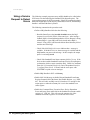
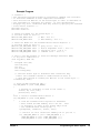
Using a Service
Request to Detect
Errors
The following example program sets up an SRQ handler to be called when
SCPI errors are detected using the Standard Event Status Register. The
program then prompts for SCPI commands. If the SCPI command results in
data in the output queue (such an query command) or an error, then the SRQ
handler is called and the data is printed.
The following summarizes the procedure used:
• Define a SRQ Handler which does the following:
-- Read the Status Byte using ireadstb. ireadstb returns the RQS
(request for service) bit in bit 6 of the status byte. After issuing a
ireadstb, RQS is cleared indicating that the Service Request is being
acknowledged. A new SRQ will not be issued unless RQS is
cleared. Using *STB? will return the Master State Summary in bit 6
and does not affect RQS.
-- Check if the MAV bit (bit 4) is set to indicate that a message is
available. If the MAV bit is set, then a message is available and the
SRQ handler can process the message. In this example, the output
queue is read using iscanf.
-- Check if the Standard Event Status summary bit (bit 5) is set. If the
bit is set then read the Standard Event Status Group’s Event Register
to determine which event(s) caused the SRQ. Check for Command
Error (bit 5), Execution Error (bit 4), Device Dependent Error (bit
3), or Query Error (bit 2). If found, read the error queue with
SYST:ERR? to print out error messages.
• Enable SRQ Handler in SICL with ionsrq.
• Enable MAV bit (Message Available Bit) and Standard Event Status
Register Summary Bit in the Status Byte Enable Register (e.g. *SRE
48). This will cause an SRQ to arrive when there is a message in the
output queue or when the summary bit is set in the standard event
status register.
• Enable the Command Error, Execution Error, Device Dependent
Error, and Query Error enable bits in the Standard Event status enable
register (e.g. *ESE 60). This will cause the summary bit of the
standard event status register to be set when an error occurs.
18
Programming the Status System
Chapter 2
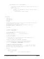
Example Program
/* status2.c *
* The following program provides an interactive command line interface
* to send SCPI commands to SCPI compatible instruments.
* This utilizes the MAV bit of the Status Byte in order to determine if
* the instrument is returning any output. It also automatically
* displays any error conditions that may result by querying the Standard
* event status register. */
#include <sicl.h>
#include <stdio.h>
/* Theses are Masks for the Status Byte */
/* all bits start at bit 0 */
#define MAV_MASK 0x10
/* MAV - bit 4 */
#define ESR_MASK 0x20
/* ESR summary - bit 5 */
/* These are Masks for the
/* all bits start at bit 0
#define QRY_ERR_MASK 0x04
#define DEV_ERR_MASK 0x08
#define EXE_ERR_MASK 0x10
#define CMD_ERR_MASK 0x20
Standard Event Status Register */
*/
/* query error - bit 2 */
/* device dependent error - bit 3 */
/* execution error - bit 4 */
/* command error - bit 5 */
/* This is the SRQ handler to check for Message Available (MAV)
* or any error conditions */
void srq_hdlr( INST id)
{
unsigned char stb;
char buf[255];
int esr;
int errnum;
char errmsg[100];
/* read the status byte to determine what caused the SRQ.
* Note: use ireadstb instead of *STB? because we want to
* clear RQS instead of reading the MSS bit in the status byte. */
ireadstb(id, &stb);
/* check if MAV caused the SRQ */
if( MAV_MASK == (stb & MAV_MASK))
{
/* message is available so read in the result */
iscanf( id, "%t", buf);
printf("%s", buf);
}
else /* check if Standard Event Status */
if( ESR_MASK == (stb & ESR_MASK))
{
/* read the standard event register to determine
* what caused the ESR summary bit to be set. This
* is necessary in order to get future SRQ’s from
* the Standard Event status group. */
ipromptf(id, "*ESR?\n", "%d\n", &esr);
/* check if an error caused the summary bit to get set */
if( (CMD_ERR_MASK == (esr & CMD_ERR_MASK )) ||
(EXE_ERR_MASK == (esr & EXE_ERR_MASK )) ||
(DEV_ERR_MASK == (esr & DEV_ERR_MASK )) ||
Chapter 2
Programming the Status System
19
(QRY_ERR_MASK == (esr & QRY_ERR_MASK ))
)
{
/* an error occurred, read the error queue to get the error */
errnum = -1;
while( errnum != 0)
{
ipromptf( id, "SYST:ERR?\n", "%d,%t", &errnum, errmsg);
if( errnum != 0)
printf("%d,%s", errnum, errmsg);
}
}
}
}
void main()
{
INST id;
char addr[80];
char cmd[255];
int opc;
int idx;
printf("This program provides an interactive environment for SCPI \n");
printf("compatible instruments. \n\n");
printf("Enter the SICL address of the instrument to open.\n");
printf("for example: iscpi,24)\n");
gets(addr);
/* install error handler */
ionerror( I_ERROR_EXIT);
/* open the instrument specified by the user */
id = iopen(addr);
itimeout( id, 20000);
/* 20 second timeout */
/* set up SRQ handler */
ionsrq( id, srq_hdlr);
/* enable MAV (bit 4) and Standard Event Status Summary (bit 5)
* in status byte to cause an SRQ */
iprintf( id, "*SRE %d\n", MAV_MASK | ESR_MASK);
/* enable ERROR Bits to generate a ESR summary message */
iprintf( id, "*ESE %d\n", CMD_ERR_MASK | EXE_ERR_MASK |
DEV_ERR_MASK | QRY_ERR_MASK);
/* make sure *SRE and *ESE finished */
ipromptf( id, "*OPC?\n", "%d", &opc);
/* opc value not used */
printf("\nEnter SCPI Commands/Queries to Instrument at %s\n", addr);
printf(" (press return to exit)\n\n");
while(1)
{
while(0 == gets(cmd));
if( 0 == strlen(cmd))
break;
/* quit sending SCPI Commands */
20
Programming the Status System
Chapter 2
/* send command */
iprintf(id, "%s\n", cmd);
/* check cmd for a ’?’, if found assume it is a query */
for(idx=0; idx<strlen(cmd); idx++)
if( ’?’ == cmd[idx])
{
/* wait up to 1 minute for srq handler */
if( 0 != iwaithdlr(60000))
{
printf("ERROR: Failed to process Query\n");
}
break;
}
}
/* while - there are commands to send */
/* remove the handler */
ionsrq( id, 0);
/* close the session */
printf("\nClosing Instrument at %s\n", addr);
iclose(id);
}
Chapter 2
Programming the Status System
21
Notes:
22
Programming the Status System
Chapter 2
Chapter 3
Command Reference
About this Chapter
This section describes the SCPI status system and common (*) commands that can
be used to program instruments in your mainframe.
Chapter 3
Command Reference
23
STATus
The STATus subsystem commands access the condition, event, and enable registers
in the Operation Status Group and the Questionable Data Group.
Subsystem Syntax
STATus
:OPERation
:CONDition?
:ENABle <event>
:ENABle?
[:EVENt]?
:PRESet
:QUEStionable
:CONDition?
:ENABle <event>
:ENABle?
[:EVENt]?
:OPERation :CONDition?
STATus:OPERation:CONDition? returns the state of the condition register in the
Operation Status Group. The state represents conditions which are part of an
instrument’s operation.
Comments
Example
• Related Commands:
STAT:OPER:ENABle, STAT:OPER:EVENt?
Reading the contents of the condition register
STAT:OPER:COND?
Query register.
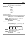
:OPERation:ENABle
STATus:OPERation:ENABle <event> sets an enable mask to allow events
monitored by the condition register and recorded in the event register, to send a
summary bit to the Status Byte register (bit 7).
Parameters
Comments
Example
Parameter
Name
Parameter
Type
Range of
Values
Default
Units
event
numeric
0-65535
none
• When the summary bit is sent, it sets bit 7 in the Status Byte register.
• Related Commands: STAT:OPER:ENABle?
Unmasking bit 8 in the Event Register
STAT:OPER:ENAB 256
24
Command Reference
Unmask bit 8.
Chapter 3
:OPERation:ENABle?
STATus:OPERation:ENABle? returns which bits in the event register (Operation
Status Group) are unmasked.
Comments
• Reading the event register mask does not change the mask setting
(STAT:OPER:ENAB <event>).
• Related Commands:
Example
STAT:OPER:ENABle
Reading the Event Register Mask
STAT:OPER:ENAB?
Query register mask.
:OPERation[:EVENt]?
STATus:OPERation[:EVENt]? returns which bits in the event register (Operation
Status Group) are set. The event register indicates when there has been a transition
in the condition register.
Comments
• Reading the event register clears the contents of the register.
If the event
register is to be used to generate a service request (SRQ), you should clear the
register before enabling the SRQ (*SRE). This prevents an SRQ from
occurring due to a previous event.
• Related Commands:
Example
STAT:OPER:ENABle, STAT:OPER:ENABle?
Reading the Event Register
STAT:OPER:EVEN?
Query returns bit(s) set.
:PRESet
STATus:PRESet Sets the Operation Status Enable and Questionable Data Enable
registers to 0. After executing this command, none of the events in the Operation
Event or Questionable Event registers will be reported as a summary bit in either the
Status Byte Group or Standard Event Group. STATus:PRESet does not clear either
of the Event registers.
Example
Presetting the Enable Register
STAT:PRES
Preset enable register.
:QUEStionable :CONDition?
STATus:QUEStionable:CONDition? returns the state of the condition register in
the Questionable Status Group. The state represents conditions which are part of an
instrument’s operation.
Chapter 3
Command Reference
25
Comments
Example
• Related Commands:
STAT:QUES:ENABle, STAT:QUES:EVENt?
Reading the contents of the condition register
STAT:QUES:COND?
Query register.
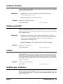
:QUEStionable:ENABle
STATus:QUEStionable:ENABle <event> sets an enable mask to allow events
monitored by the condition register and recorded in the event register, to send a
summary bit to the Status Byte register (bit 3).
Parameters
Comments
Example
Parameter
Name
Parameter
Type
Range of
Values
Default
Units
event
numeric
0-65535
none
• When the summary bit is sent, it sets bit 3 in the Status Byte register.
• Related Commands: STAT:QUES:ENABle?
Unmasking bit 8 in the Event Register
STAT:QUES:ENAB 256
Unmask bit 8.
:QUEStionable:ENABle?
STATus:QUEStionable:ENABle? returns which bits in the event register
(Questionable Status Group) are unmasked.
Comments
• Reading the event register mask does not change the mask setting
(STAT:QUES:ENAB <event>).
• Related Commands:
Example
STAT:QUES:ENABle
Reading the Event Register Mask
STAT:QUES:ENAB?
Query register mask.
:QUEStionable[:EVENt]?
STATus:QUEStionable[:EVENt]? returns which bits in the event register
(Questionable Status Group) are set. The event register indicates when there has
been a transition in the condition register.
Comments
26
Command Reference
• Reading the event register clears the contents of the register.
If the event
register is to be used to generate a service request (SRQ), you should clear the
register before enabling the SRQ (*SRE). This prevents an SRQ from
occurring due to a previous event.
Chapter 3
• Related Commands:
Example
Reading the Event Register
STAT:QUES:EVEN?
Chapter 3
STAT:QUES:ENABle, STAT:QUES:ENABle?
Query returns bit(s) set.
Command Reference
27
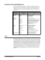
Common Command Reference
This section describes the IEEE-488.2 Common Commands that can be used to
program instruments in the mainframe. Commands are listed alphabetically (the
following table shows the Common Commands listed by functional group). For
additional information on any Common Commands, refer to the IEEE Standard
488.2-1987.
IEEE 488.2 Common Commands Functional Groupings
Category
Command
Title
General
*IDN?
*RST
*TST?
Identification Query
Reset Command
Self-Test Query
Instrument
Status
*CLS
*ESE <mask>
*ESE?
*ESR?
*SRE <mask>
*SRE?
*STB?
Clear Status Command
Standard Event Status Enable Command
Standard Event Status Enable Query
Standard Event Status Register Query
Service Request Enable Command
Service Request Enable Query
Status Byte Query
*DMC <name>,<cmds>
*EMC <state>
*EMC?
*GMC? <name>
*LMC?
*PMC
*RMC <name>
Define Macro Command
Enable Macros Command
Enable Macro Query
Get Macro Query
Learn Macro Query
Purge all Macros Command
Remove individual Macro Command
*OPC
*OPC?
*WAI
Operation Complete Command
Operation Complete Query
Wait-to-Continue Command
Macros
Synchronization
*CLS
Clear Status Command. The *CLS command clears all status registers (Standard
Event Status Register, Standard Operation Event Status Register, Questionable Data
Event Register) and the error queue for an instrument. This clears the corresponding
summary bits (bits 3, 5, & 7) and the instrument-specific bits (bits 0, 1, & 2) in the
Status Byte Register. *CLS does not affect the enabling of bits in any of the status
registers (Status Byte Register, Standard Event Status Register, Standard Operation
Enable Status Register, or Questionable Data Enable Status Register). (The SCPI
command STATus:PRESet does clear the Standard Operation Status Enable and
Questionable Status Enable registers.) *CLS disables the Operation Complete
function (*OPC command) and the Operation Complete Query function (*OPC?
command).
28
Command Reference
Chapter 3
*DMC <name_string>, <command_block>
Define Macro Command. Assigns one, or a sequence of commands to a macro
name.
The command sequence may be composed of SCPI and/or Common commands.
The name given to the macro may be the same as a SCPI command, but may not be
the same as a Common command. When a SCPI named macro is executed, the
macro rather than the SCPI command is executed. To regain the function of the
SCPI command, execute the *EMC 0 command.
*EMC <enable>
Enable Macros Command. When enable is non-zero, macros are enabled. When
enable is zero, macros are disabled.
*EMC?
Enable Macros Query. Returns either 1 (macros are enabled), or 0 (macros are
disabled) for the selected instrument.
*ESE <mask>
Standard Event Status Enable Register Command. Enables one or more events
in the Standard Event Status Register to be reported in bit 5 (the Standard Event
Status Summary Bit) of the Status Byte Register. You enable an event by specifying
its decimal weight for <mask>. To enable more than one event, specify the sum of
the decimal weights.
Example
*ESE 60
Enables bits 2, 3, 4, & 5. Respective
weights are 4 + 8 + 16 + 32 = 60.
*ESE?
Standard Event Status Enable Query. Returns the weighted sum of all enabled
(unmasked) bits in the Standard Event Status Register.
Example
ESE?
Sends status enable query.
*ESR?
Standard Event Status Register Query. Returns the weighted sum of all set bits
in the Standard Event Status Register. After reading the register, *ESR? clears the
register. The events recorded in the Standard Event Status Register are independent
of whether or not those events are enabled with the *ESE command.
Chapter 3
Command Reference
29
Example
*ESR?
Sends Standard Event Status Register
query.
*GMC? <name_string>
Get Macro Query. Returns arbitrary block response data which contains the
command or command sequence defined by name_string. The command sequence
will be prefixed with characters which indicate the number of characters that follow
the prefix.
Example
*GMC? ‘ LIST’
Ask for definition of macro from *DMC
example.
If the prefix returned consisted of "#214", the 2 says to expect two
character-counting digits. The 14 says that 14 characters of data follow. Had the
returned macro been shorter, such as #15*EMC?, we would read this as 1 counting
digit indicating 5 data characters.
*IDN?
Identity. Returns the device identity. The response consists of the following four
fields (fields are separated by commas):
• Manufacturer
• Model Number
• Serial Number (returns 0 if not available)
• Firmware Revision (returns 0 if not available)
The *IDN? command returns something similar to the following for the
HP E1411B:
HEWLETT-PACKARD,E1411B,0,B,05.00
Example
*IDN?
Queries identity.
*LMC?
Learn Macros Query. Returns a quoted string name for each currently defined
macro. If more than one macro is defined, the quoted strings are separated by
commas (,). If no macro is defined, then a quoted null string ("") is returned.
*LRN?
Learn query command. *LRN? causes the instrument to respond with a string of
SCPI commands which define the instrument’s current state. Your application
program can enter the *LRN? response data into a string variable, later to be sent
back to the instrument to restore that configuration.
Example response from an HP E1326B voltmeter in the power-on state:
30
Command Reference
Chapter 3
*RST;:CAL:ZERO:AUTO 1; :CAL:LFR +60; VAL +0.00000000E+000;
:DISP:MON:STAT 0; CHAN (@0); :FORM ASC,+7; :FUNC "VOLT";
:MEM:VME:ADDR +2097152; SIZE +0; STAT 0; :RES:APER +1.666667E-002;
OCOM 0; RANG +1.638400E+004; RANG:AUTO 1;:VOLT:APER
+1.666667E-002; RANG +8.000000E+000; RANG:AUTO 1; :TRIG:COUN +1;
DEL +0.00000000E+000; DEL:AUTO 1; :TRIG:SOUR IMM; :SAMP:COUN +1;
SOUR IMM;TIM +5.000000E-002 S
*OPC
Operation Complete. Causes an instrument to set bit 0 (Operation Complete
Message) in the Standard Event Status Register when all pending operations have
been completed. By enabling this bit to be reflected in the Status Byte Register
(*ESE 1 command), you can ensure synchronization between the instrument and an
external computer or between multiple instruments.
*OPC?
Operation Complete Query. Causes an instrument to place an ASCII 1 into the
instrument’s output queue when all pending instrument operations are finished. By
requiring the computer to read this response before continuing program execution,
you can ensure synchronization between one or more instruments and the computer.
*PMC
Purge Macros Command. Purges all currently defined macros in the selected
instrument.
*RMC <name_string>
Remove Individual Macro Command. Purges an individual macro identified by
the name_string parameter.
Example
*RMC ‘ LIST’
Remove macro command from *DMC
example.
*RST
Reset. Resets an instrument as follows:
• Sets the instrument to a known state (usually the power-on state).
• Aborts all pending operations.
• Disables the *OPC and *OPC? modes.
*RST does not affect:
• The state of the VXI interface
• The VXI address
Chapter 3
Command Reference
31
• The output queue
• The Service Request Enable Register
• The Standard Event Status Enable Register
• The power-on flag
• Calibration data
• Protected user data
*SRE <mask>
Service Request Enable. When a service request event occurs, it sets a
corresponding bit in the Status Byte Register (this happens whether or not the event
has been enabled (unmasked) by *SRE). The *SRE command allows you to identify
which of these events will assert a service request (SRQ). When an event is enabled
by *SRE and that event occurs, it sets a bit in the Status Byte Register and issues an
SRQ to the computer. You enable an event by specifying its decimal weight for
<mask>. To enable more than one event, specify the sum of the decimal weights.
Example
*SRE 160
Enables bits 5 & 7. Respective weights
are 32 + 128 = 160.
*SRE?
Status Register Enable Query. Returns the weighted sum of all enabled
(unmasked) events (those enabled to assert SRQ) in the Status Byte Register.
Example
*SRE?
Sends Status Register Enable query.
*STB?
Status Byte Register Query. Returns the weighted sum of all set bits in the Status
Byte Register.
Comments
Example
You can read the Status Byte Register using either the *STB? command or by doing
a SICL ireadstb function call. There are some subtle differences between *STB? and
ireadstb. You can use either method to read the state of bits 0-5 and bit 7. Bit 6 is
treated differently depending on whether you use *STB? or ireadstb. In general, use
ireadstb inside interrupt service routines, not *STB?.
*STB?
Sends Status Byte Register query.
*TST?
Self-Test. Causes an instrument to execute an internal self-test and returns a
response showing the results of the self-test. A zero response indicates that self-test
passed. A value other than zero indicates a self-test failure or error.
Example
32
Command Reference
*TST?
Execute self-test, return response.
Chapter 3
*WAI
Wait-to-continue. Prevents an instrument from executing another command until
the operation caused by the previous command is finished (sequential operation).
Since all instruments normally perform sequential operations, executing the *WAI
command causes no change to the instrument’s operation.
Chapter 3
Command Reference
33
Notes:
34
Command Reference
Chapter 3