1
HP Performance Optimized Datacenter 20c
User Guide—International
Abstract
This guide is intended for the person who operates and maintains the HP Performance Optimized Datacenter 20c (HP POD 20c).
Part Number: 703549-001
March 2013
Edition: 1
© Copyright 2013 Hewlett-Packard Development Company, L.P.
The information contained herein is subject to change without notice. The only warranties for HP products and services are set forth in the express
warranty statements accompanying such products and services. Nothing herein should be construed as constituting an additional warranty. HP shall
not be liable for technical or editorial errors or omissions contained herein.
Confidential computer software. Valid license from HP required for possession, use or copying. Consistent with FAR 12.211 and 12.212,
Commercial Computer Software, Computer Software Documentation, and Technical Data for Commercial Items are licensed to the U.S. Government
under vendor’s standard commercial license.
Microsoft® and Windows® are U.S. registered trademarks of Microsoft Corporation.
Intel® Core™ is a trademark of Intel Corporation in the U.S. and other countries.
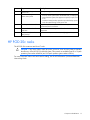
Contents
Overview ..................................................................................................................................... 6
Before you begin....................................................................................................................................... 6
Operator safety......................................................................................................................................... 6
Component safety ..................................................................................................................................... 6
Fire detection and suppression .................................................................................................................... 7
Environmental considerations ...................................................................................................................... 7
Component identification ............................................................................................................... 8
Structural component identification .............................................................................................................. 8
Parts and part number identification ................................................................................................... 8
Life safety component identification ............................................................................................................. 9
Electrical power component identification ................................................................................................... 12
Control cabinet component identification .................................................................................................... 16
HP POD 20c racks .................................................................................................................................. 17
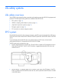
Life safety systems ....................................................................................................................... 18
Life safety overview ................................................................................................................................. 18
EPO system ............................................................................................................................................ 18
ECS touchscreen and EPO indicators ............................................................................................... 19
EPO modes................................................................................................................................... 20
EPO accidental activation ............................................................................................................... 20
Battery backup during an EPO event ................................................................................................ 20
VESDA air sampling smoke detection system............................................................................................... 21
(Optional) Fire protection system ............................................................................................................... 21
Manual fire button ......................................................................................................................... 21
Fire alarm indicators ...................................................................................................................... 22
Fire suppression system .................................................................................................................. 22
Emergency egress ................................................................................................................................... 24
Power, electrical, and controls ...................................................................................................... 25
Site electrical system ................................................................................................................................ 25
Power safety ........................................................................................................................................... 25
Grounding .................................................................................................................................... 25
Capacities .............................................................................................................................................. 27
HP POD 20c capacity limitations ..................................................................................................... 27
Electrical and mechanical cooling capacities .............................................................................................. 27
Power feeders ......................................................................................................................................... 27
Electrical panels ...................................................................................................................................... 28
Arc flash safety ............................................................................................................................. 28
Power distribution: electrical busway system ..................................................................................... 28
Panel schedules ............................................................................................................................. 29
Wire color code ............................................................................................................................ 29
Electrical busways ................................................................................................................................... 30
Drop boxes ............................................................................................................................................ 31
Power configurations ............................................................................................................................... 32
Rack power ............................................................................................................................................ 32
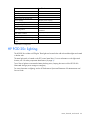
HP POD 20c lighting ............................................................................................................................... 33
Contents
3
Environmental control system ........................................................................................................ 34
Environmental control system overview ....................................................................................................... 34
Using the ECS ......................................................................................................................................... 34
Sensors ........................................................................................................................................ 35
Facility connections to ECS ....................................................................................................................... 38
Connecting to the ECS ................................................................................................................... 38
Managing the ECS from the HP POD 20c................................................................................................... 39
Configuring the ECS ...................................................................................................................... 39
Logging in remotely to the ECS ........................................................................................................ 41
Password protection ................................................................................................................................ 43
Navigating the ECS interface .................................................................................................................... 43
Logging in to the ECS touchscreen ................................................................................................... 44
Overview screen ........................................................................................................................... 45
Status Overview screen .................................................................................................................. 47
Basic System Configuration screen ................................................................................................... 47
Advanced System Configuration screen ............................................................................................ 52
Controller Settings screen ............................................................................................................... 55
I/O Overview screen ..................................................................................................................... 57
ECS alarms ............................................................................................................................................ 57
Safety and access control alarms ..................................................................................................... 58
Cooling system ........................................................................................................................... 59
HP POD 20c cooling system theory of operation ......................................................................................... 59
Water supply temperature .............................................................................................................. 59
Water quality requirements and specifications .................................................................................. 60
Cooling system components ...................................................................................................................... 61
Fans ............................................................................................................................................ 62
Condensation management ...................................................................................................................... 63
Drains .......................................................................................................................................... 63
Leak detection ............................................................................................................................... 65
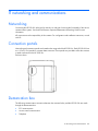
IT networking and communications ............................................................................................... 66
Networking ............................................................................................................................................ 66
Connection portals .................................................................................................................................. 66
Demarcation box .................................................................................................................................... 66
Fire box ................................................................................................................................................. 67
Optional components .................................................................................................................. 68
Fire protection system .............................................................................................................................. 68
Humidifier .............................................................................................................................................. 68
Controlled access .................................................................................................................................... 68
Power up procedure .................................................................................................................... 69
Standard HP POD 20c power up procedure ............................................................................................... 69
Power up checklist ......................................................................................................................... 69
Standard power up procedure ........................................................................................................ 70
Cold weather HP POD 20c power up procedure ......................................................................................... 70
Cold weather power up checklist ..................................................................................................... 71
Standard power up procedure ........................................................................................................ 71
Power down procedure ............................................................................................................................ 73
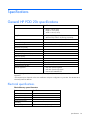
Specifications ............................................................................................................................. 74
General HP POD 20c specifications .......................................................................................................... 74
Electrical specifications .................................................................................................................. 74
Water specifications ...................................................................................................................... 75
Contents
4
Rack specifications .................................................................................................................................. 75
Thermal and air flow performance ............................................................................................................. 75
Environmental specifications ..................................................................................................................... 75
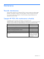
Maintenance .............................................................................................................................. 77
Periodic maintenance .............................................................................................................................. 77
Sample HP POD 20c maintenance schedule ............................................................................................... 77
Contacting HP ............................................................................................................................ 78
Before you contact HP.............................................................................................................................. 78
HP contact information ................................................................................................................... 78
Regulatory information ................................................................................................................ 79
HP POD 20c regulatory compliance .......................................................................................................... 79
Safety and IEC compliance ............................................................................................................. 79
Safety and regulatory compliance ............................................................................................................. 80
Turkey RoHS material content declaration ................................................................................................... 80
Ukraine RoHS material content declaration ................................................................................................. 80
Warranty information .............................................................................................................................. 80
Glossary .................................................................................................................................... 81
Documentation feedback ............................................................................................................. 84
Index ......................................................................................................................................... 85
Contents
5
Overview
Before you begin
For more information on site requirements, specifications, power requirements, management requirements,
and supported facility connections, see the HP Performance Optimized Datacenter 20c Site Preparation and
Requirements Guide.
This guide is part of the core documentation for the HP POD 20c. The actual location of various components
or included subsystems and their operation in your HP POD 20c might vary from what is described in this
document. For information specific to your HP POD 20c, see the drawings included in the Operations and
Maintenance Manual for the HP Performance Optimized Datacenter 20c, or contact HP.
Operator safety
The HP POD 20c is not suitable for long-term human occupancy. The HP POD 20c is Listed as a Product that
provides service access areas for periodic maintenance and service. These areas must be used only by
owner-authorized and qualified personnel who are trained in the maintenance and service of the HP POD
20c components.
WARNING: To avoid the risk of personal injury or loss of life, all personnel must comply with PPE
requirements when opening or working inside areas of the HP POD 20c that are marked as
hazardous voltage, in accordance with NFPA 70 (NA) and IEC (EMEA and APJ).
WARNING: To avoid the risk of personal injury, hearing protection must be worn at all times
when working inside the HP POD 20c.
WARNING: To avoid the risk of personal injury or damage to the equipment, do not insert
anything inside the electrical busways, except for the approved HP busway drop boxes.
Before completing the HP POD 20c, the customer, or a designated agent, is responsible for completing any
Environmental Health and Safety evaluation of the HP POD 20c or any attached structural component
purchased through HP. The customer must complete an arc flash assessment of the HP POD 20c and the
associated electrical supply system for operation, maintenance, and so on.
Component safety
CAUTION: If the HP POD 20c is shut down for an extended period of time, such as during
routine maintenance, use desiccant units or materials to eliminate condensation within the HP
POD 20c. Condensation causes damage to IT equipment and HP POD 20c controls.
CAUTION: Electrostatic discharge might damage electronic components. Be sure that you are
properly grounded (earthed) by wearing approved grounding straps before beginning any
installation procedure or repair.
Overview 6
CAUTION: If any racks contain empty RU space, use the HP POD 20c filler panels to maintain
the efficiency of the HP POD 20c thermal system. Filler panels are available from HP in 10-pack
quantities (part number AQ682A) and 100-pack quantities (part number AS993A).
Fire detection and suppression
The fire suppression system, supplied as an optional component for the HP POD 20c, is a "Manufacturer
Designed" system specifically designed for this HP product, in compliance with national standards.
The HP standard suppression system includes a Novec 1230 clean agent system. However, if the customer
or local Authorities require specific modifications or a replacement, HP can assist in these actions at the
expense of the customer.
HP does not certify that the fire suppression system that is installed in the HP POD 20c meets all local and
jurisdictional requirements. The customer is responsible for the following actions as related to the fire
suppression system:
•
Verifying that the POD suppression system meets local codes, including specific local requirements for
initial and periodic inspections
•
Arranging for and receiving all required local permits, including initial commissioning as well as
standard and repair maintenance
•
Arranging for the connection of the agent tanks, refilling of tanks, and all system testing, including
pressure tests. All general maintenance of the suppression system must be completed by an authorized
technician.
Additional local requirements are not covered as part of the option price or basic installation and
deployment services, unless specifically included in an executed Statement of Work.
Environmental considerations
CAUTION: To maintain accurate environmental conditions and minimize condensation inside
the HP POD 20c, do not leave the HP POD 20c doors open during operation.
Overview 7
Component identification
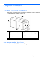
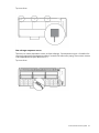
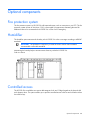
Structural component identification
The HP POD 20c documentation frequently refers to the specific components of the HP POD 20c as shown
in the following figure and described in the following table.
Item
Component
Description
1
Heat exchanger access hatches
Enables access to the overhead heat exchangers
2
Emergency egress door
Provides access to the POD in the event of an
emergency
3
Personnel access door
Provides access to the POD
4
Facility chilled water return
Facilitates the return of chilled water to the POD
5
Facility chilled water supply
Facilitates the supply of chilled water to the POD
Parts and part number identification
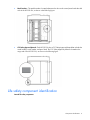
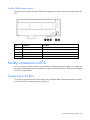
Review the contents of the HP POD 20c to identify the following for each component:
Component identification 8
•
Model number—The model number is located adjacent to the door to the control panel inside the cold
aisle of the HP POD 20c, as shown in the following figure.
•
CSC Safety Approval placard—Each HP POD 20c has a CSC Safety Approval placard that includes the
model number, serial number, and proof load. The CSC Safety Approval placard is located on the
cargo end of the HP POD 20c, as shown in the following figure.
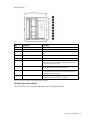
Life safety component identification
Internal life safety components
Component identification 9
End view shown
Item
Component
Description
1
Fire strobe light
Indicates a fire alarm condition within the HP POD 20c
2
Fire horn
Indicates a fire alarm condition within the HP POD 20c
3
EPO strobe
Amber—An EPO event occurred and the HP POD 20c shut
down
4
ECS power switch
Turns the main power to the 24V ECS system off and on
5
Main light switch
Turns power to the HP POD 20c lights off and on
6
Fire alarm manual button
Enables manual initiation of the fire system, which includes
activating the interior and exterior fire strobe lights and the
optional fire suppression system
7
Fire suppression abort button*
Aborts the fire suppression system. A fire suppression abort
button is located next to each personnel door.
8
Fire alarm manual button
Enables manual initiation of the fire system, which includes
activating the interior and exterior fire strobe lights and the
optional fire suppression system
9
Fire suppression abort button*
Aborts the fire suppression system. A fire suppression abort
button is located next to each personnel door.
*This is an optional component that might not be included.
Internal emergency status indicators
The HP POD 20c has one fire strobe light that indicates a fire alarm condition.
Component identification 10
End view shown
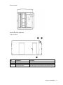
External life safety components
Side view shown
Item
Component
Description
1
Fire strobe light
Indicates a fire alarm condition within the HP POD 20c
2
Fire horn
Indicates a fire alarm condition within the HP POD 20c
3
Optional EPO button
Manually triggers an EPO shutdown within the HP POD 20c
Component identification 11
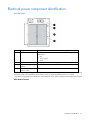
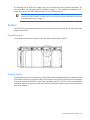
Electrical power component identification
Front view shown
Item
Component
Description
1
Demarcation box1
Customer communication connection point for the following
components:
•
•
•
ECS
Access control
Phone
2
Fire box1
Connection location for fire emergency and VESDAnet signals
3
480/415 transformer
cabinet2
380-415 VAC WYE,
3-phase, 320 A
Converts main power from 480V to 415V for POD operation
4
Feed A and B power for IT critical loads busways and house power
The demarcation box and the fire box are communication data points that are provided on the POD by HP. Connecting
these data points is the responsibility of the customer, unless an approved Statement of Work is initiated.
2
This cabinet is designed for two transformers. The transformers are an optional component that might not be included.
1
Main breaker locations
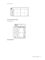
Component identification 12
Side view shown
Critical IT and transformer cabinet
Front view shown
External panel labels
Component identification 13
Front view shown
Item
Electrical safety label
Description
1
House panel cabinet high
voltage
Provides a reminder to users there are high voltage electrical
components inside the cabinet
2
Transformer cabinet high
voltage warning
Provides a reminder to users there are high voltage
transformers inside the cabinet
3
Disconnect label
Provides the order for disconnecting the electrical panels
4
Short circuit current label
States that the design of the POD can withstand the available
fault current and describes the electrical system
5
Arc flash warning
Provides a reminder to users of the danger of arc flash and
required PPE
6
Grounding label
Indicates the location of the grounding electrode connection
point
Side view shown
Component identification 14
Item
Electrical safety label
Description
1
Main power cabinet high
voltage
Provides a reminder to users there are high voltage electrical
components inside the cabinet
2
Do not enter label
Provides a warning to users not to enter while a fire is
extinguishing
4
Power disconnect label
States that power should be disconnected before maintenance
is performed
5
Short circuit current label
States that the design of the POD can withstand the available
fault current and describes the electrical system
6
Arc flash warning
Provides a reminder to users of the danger of arc flash and
required PPE
Internal panel labels
Front view shown
Item
Electrical safety label
Description
1
Power feeders caution label
Cautions users about phase rotation for all power feeders
2
Wire color code
Lists the 380-415 Y/200-240 V color codes:
•
•
•
•
•
3
Panel schedule/circuit breaker
table/fuse list
Brown—Phase A/L1
Black—Phase B/L2
Grey—Phase 3/L3
Blue—Neutral
Green and yellow—Equipment ground
Lists the layout and designation for all circuit breakers and lists
all fuse types and sizes
Component identification 15
Side view shown
1
Power feeders caution label
2
Wire color code
3
Cautions users about phase rotation for all power feeders
Lists the 380-415 Y/200-240 V color codes:
•
•
•
•
•
Panel schedule/circuit breaker
table/fuse list
Brown—Phase A/L1
Black—Phase B/L2
Grey—Phase 3/L3
Blue—Neutral
Green and yellow—Equipment ground
Lists the layout and designation for all circuit breakers and lists
all fuse types and sizes
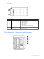
Control cabinet component identification
Component identification 16
Item
Component
Description
1
VESDA air sampling smoke
detection unit
Fire alarm and suppression
release control panel
An early warning, laser scan smoke detection unit
2
•
•
Controls all fire systems within the HP POD 20c, including the
smoke detection system, fire suppression system, fire pulls, and
so on
Includes a battery backup system that provides backup power
to the fire system during a utility power loss
3
ECS relays and ECS modules
Relays for the ECS control, ECS communications, I/O connections,
and terminal block connections
4
EPO controller board and house Connections for the EPO system and fuses for other house panel
panel fuses
components
5
Dual power supplies with
battery backup
Provides 24 V DC power to the PLC, LED lighting, and ECS systems
HP POD 20c racks
The HP POD 20c contains a total of ten IT racks.
CAUTION: If any racks contain empty RU space, use the HP POD 20c filler panels to maintain
the efficiency of the HP POD 20c thermal system. Filler panels are available from HP in 10-pack
quantities (part number AQ682A) and 100-pack quantities (part number AS993A).
For more information about racks and network cabling, see the HP Performance Optimized Datacenter
Networking Guide.
Component identification 17
Life safety systems
Life safety overview
The HP POD 20c has multiple life safety systems that work together to protect the HP POD 20c equipment and
personnel. The following life safety systems are available on the HP POD 20c:
•
EPO system (on page 18)
•
VESDA air sampling smoke detection system (on page 21)
•
(Optional) fire protection system (on page 21)
•
Emergency egress (on page 24)
•
ECS connection to customer emergency systems
EPO system
If the HP POD 20c must be shut down during an emergency, the EPO system automatically shuts off all power
to the HP POD 20c and activates the EPO indicator on the ECS panel door and the EPO strobe on the POD
interior.
To ensure that all rack-mounted UPS devices are shut down during an EPO event, verify that each
rack-mounted UPS device is connected to the HP POD 20c EPO system.
The EPO system can be activated two ways:
•
Excessive high temperature in the hot aisle—The HP POD 20c includes two EPO temperature sensors.
If both sensors reach 60°C (140°F), an EPO shutdown is triggered automatically. Both sensors are
located in zone 2.
•
Manual initiation—To manually trigger an EPO shutdown, press either of the EPO buttons. One EPO
button is located on the POD interior near the main exit, and an optional second EPO button is located
on the POD exterior.
Life safety systems
18
For the location of EPO buttons, see "Life safety component identification (on page 9)."
The EPO system must be reset before you can power up and restart the HP POD 20c. To reset the EPO system:
1.
Verify that the key control for the EPO mode is in the Armed position.
2.
Press the white EPO Reset button.
If you triggered the EPO system manually, you must reset the EPO button that you pressed to the Active
position.
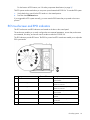
ECS touchscreen and EPO indicators
The ECS touchscreen and EPO indicators are located on the door to the control panel.
The touchscreen enables you to easily configure the environmental parameters, access data, and monitor
environmental, life safety, and access control conditions within the HP POD 20c.
The EPO indicators provide EPO status. The EPO key control and EPO reset button enable you to adjust the
EPO system mode.
Item Component
Indicator Color
Description
White
Indicates the EPO power status for main
power feed A
1
Source A available indicator
2
Source A wrong rotation indicator Red
Indicates the Source A power phase
rotation is incorrect
3
Source B wrong rotation indicator Red
Indicates the Source B power phase
rotation is incorrect
4
Source B available indicator
White
Indicates the EPO power status for main
power feed B
5
EPO shutdown indicator
Red
Indicates an EPO shutdown or alarm
situation
6
EPO armed indicator
White
Indicates that the EPO system is armed and
operational
7
EPO reset button
Blue
Resets the EPO system when pressed
Life safety systems
19
Item Component
Indicator Color
Description
8
EPO mode key control
—
Enables you to select the EPO mode. For
more information, see "EPO modes (on
page 20)."
9
EPO shutdown button
Red
Initiates a manual EPO event
10
Light test button
—
Tests all the EPO LED indicators when
pressed
11
EPO bypass mode indicator
Green
Indicates that the EPO shut down
functionality is bypassed
12
EPO test mode indicator
Yellow
Indicates that the EPO system is operating
in test mode or that an EPO cover is open
13
Main light switch
—
Turns power to the HP POD 20c lights off
and on
14
ECS power switch
—
Turns the main power to the 24V ECS
system off and on
EPO modes
The EPO system has three operating modes:
•
Armed—The EPO system is armed and operational.
•
Test—The EPO system is in test mode and does not initiate during events that normally trigger an EPO.
•
Bypass—The EPO system is non-operational and does not initiate during events that normally trigger an
EPO.
EPO accidental activation
To help prevent accidentally pressing the EPO button and activating the EPO system, each EPO button is
covered with a clear Lexan cover.
Battery backup during an EPO event
The following components are equipped with a UPS to help ensure that service is not interrupted during a loss
of power to the HP POD 20c:
•
ECS system
•
VESDA air sampling smoke detection system (on page 21)
•
(Optional) fire suppression system (on page 22)
•
Emergency lighting in the HP POD 20c
IMPORTANT: All Critical IT UPS devices with batteries that exceed 700VA must be connected to
the HP POD 20c EPO system, to ensure that the UPS batteries are disconnected during an EPO
event. For more information on connecting UPS devices to the EPO system, see the HP
Performance Optimized Datacenter 20c Maintenance and Service Guide.
Life safety systems
20
VESDA air sampling smoke detection system
CAUTION: Excess dust within the HP POD 20c can cause the VESDA smoke detector to trigger
a fire alarm.
The VESDA system features a single-zone laser scan, early warning smoke detector to provide the earliest
warning of a potential fire.
The red VESDA piping that runs throughout the HP POD 20c includes inlets for smoke sampling. The VESDA
uses a high-efficiency aspirator to continuously draw in air from the HP POD 20c and circulate the air through
a dual-stage filter:
•
Stage 1—A filter removes dust and dirt from the air sample.
•
Stage 2—An ultra-fine filter removes remaining contaminants in the air sample.
After the air passes through the dual-stage filter, it enters a calibrated detection chamber where a laser scans
the air sample for the presence of smoke. The VESDA system cycles through two levels if smoke is detected:
•
Level 1—Smoke concentration reaches the first setpoint, and then the VESDA system sends an alarm
signal indicating that a fire might exist.
•
Level 2—Smoke concentration reaches the second setpoint, and then the VESDA system indicates that
a fire does exist in the HP POD 20c and sends an alarm signal and an activation signal to the fire
suppression system.
IMPORTANT: The VESDA filter must be changed regularly to ensure accurate smoke detection
readings. For more information about changing the VESDA filters, see the HP Performance
Optimized Datacenter 20c Maintenance and Service Guide.
(Optional) Fire protection system
Each HP POD 20c is equipped with a fire alarm panel that is integrated with the fire detection system and the
optional fire suppression system.
The fire system is designed as a stand-alone system, but can also interface with customer site fire alarm
systems. Customer site connections are the responsibility of the customer. Consult with HP for connection
locations.
The fire protection system includes:
•
Manual fire button (on page 21)
•
Fire alarm indicators (on page 22)
•
Fire suppression system (on page 22)
Manual fire button
The HP POD 20c includes two fire buttons. One fire button is located next to the personnel access door and
the second fire button is located in the fire suppression bump out.
Manually activating a fire button does the following:
•
Activates the POD fire alarm system horn and strobe lights
Life safety systems
21
•
Triggers a fire alarm signal to the BMS in the fire box (on page 67) and activates a 30-second delay
before releasing the fire suppression agent
IMPORTANT: The fire suppression abort button does not delay the release of the fire suppression
agent if a manual fire button is initiated. The release of the fire suppression agent is imminent and
all personnel should evacuate immediately.
Fire alarm indicators
Upon activation of a fire alarm within the HP POD 20c, the following alarms alert personnel:
•
Strobe light—The HP POD 20c includes two fire strobe lights. One is located in the cold aisle and one
is located on the POD exterior.
•
Audible horn—The HP POD 20c includes two audible horns. One is located in the cold aisle and one
is located on the POD exterior.
•
Alarm within the ECS—The ECS system notifies you of a fire alarm condition with an alarm alert on the
ECS screen.
Fire suppression system
WARNING: Fire suppression agents include a pre-discharge warning and evacuating system. In
the event of a fire, all protected space must be evacuated as soon as possible.
CAUTION: The POD fire suppression system is manufacturer designed, engineered, and
installed to comply with national standards. However, HP does not certify that the installed fire
suppression system meets all local jurisdictional requirements. Compliance with local codes is
your responsibility, and includes specific local requirements for initial and periodic inspections,
certifications, and maintenance.
Any additional local requirements are not covered as part of the option price or basic installation
and deployment services, unless specifically included in an executed Statement of Work.
IMPORTANT: The fire suppression abort buttons that are located on the ECS panel and next to
the fire suppression cylinders can be pressed to interrupt the 60-second fire suppression agent
release delay of the VESDA system. Pressing either of these buttons resets the fire suppression
agent release delay to 10 seconds. Pressing and holding either of the fire suppression abort
buttons stops the agent release. Releasing the fire suppression abort button that is being held
gives personnel 10 seconds to evacuate before agent release. The fire suppression abort buttons
do not operate if a manual fire button is activated.
The fire suppression system contains conventional fire alarm control circuits and includes features required
for single or dual-hazard suppression release applications, including a low-toxicity agent. In the event of fire
suppression release, the suppression tanks must be refilled by a certified technician.
Fire system operator panel
The panel is configured by the manufacturer in accordance with the local fire marshal and fire code
requirements.
The operator panel includes the following:
•
Alarm status LED
Life safety systems
22
•
Trouble status LED
•
Input status LED
•
Output status LED
•
Acknowledge button
•
Alarm Silence button
•
System Reset button
The fire system and panel are tested by the local certified fire system supplier and witnessed and certified by
the local Authorities or fire marshal.
The fire system operator panel requires regular maintenance and service. For more information on the fire
system operator panel component, see the Operation and Maintenance Manual for the HP Performance
Optimized Datacenter 20c.
Fire suppression sequence of operations
There are two initiation sequences for the fire suppression system, automatic (VESDA) initiation and manual
initiation. The fire strobe light is activated by either initiation sequence.
Personnel can determine the status of the system by the differences of the alarm horn. The following table
describes the fire suppression system status.
Fire suppression
system stages
Beats per minute
Description
Personnel actions
Personnel may investigate
Warning
20
An alarm condition exists
Pre-discharge
120
Post-discharge
Steady
Countdown to fire suppression
Personnel should evacuate
agent has started
Fire suppression agent is released Personnel should not enter,
contact local Authorities
The fire system operator panel indicates which initiation sequence has begun with indicator lights and a
panel alarm. These signals are also available to the site BMS system, if connected.
After the fire suppression system is activated by a VESDA signal or a manual fire button, a 60-second
countdown begins before the fire suppression agent is released to the HP POD 20c interior through the fire
suppression system piping.
VESDA initiation
The VESDA fire suppression system signal has two levels that the system cycles through when smoke is
detected.
•
Level 1—Indicates that the potential for a fire is present. The strobes are illuminated and the horns are
in the Warning stage. A fire has not yet been detected and personnel may investigate to determine if
there is a potential for a fire or if a false indication has occurred.
•
Level 2—Indicates that fire does exist. VESDA Level 1 has already have been reached, the strobes
illuminate, and the horn progresses to the Pre-discharge stage. A 60-second countdown to fire
suppression agent release begins and personnel should evacuate immediately.
Press the fire suppression abort button to interrupt the fire suppression release countdown. Pressing the abort
button resets the countdown to 10 seconds, regardless of the amount of time elapsed from the original
60-second countdown. The abort button can be pressed multiple times to reset the fire suppression release
Life safety systems
23
agent countdown to 10 seconds. The fire suppression agent is released when the countdown is exhausted
and the horn progresses to the Post-discharge stage.
Personnel can press and hold the fire suppression abort button to stop the original 60-second initiation
sequence. When the abort button is released, the system countdown resets to 10 seconds. The fire
suppression agent release begins when the 10-second countdown is over and the horn progresses to the
Post-discharge stage.
Manual initiation
Manual initiation causes the fire strobe lights to illuminate, the horn goes to the Pre-discharge stage, and a
30-second countdown until the fire suppression agent release begins. The agent release is certain at this time
and cannot be aborted. After the fire suppression agent is released, the system goes to the Post-discharge
stage.
The fire suppression abort button is inactive if a manual fire pull was activated and the release of the fire
suppression agent is imminent. All personnel should immediately evacuate.
Emergency egress
The HP POD 20c includes the following features for life safety egress on all access doors:
•
Panic bar
•
Door strikes
o
Standard hardware—Door strikes
o
Optional hardware—Electric door strikes
Each personnel door includes a standard panic bar to ensure safe exit. The optional egress hardware
included in the HP POD 20c (including electric panic bars, electric strikes, and magnetic locks) are tied to the
fire alarm to enable uninhibited egress in the event of an emergency.
Life safety systems
24
Power, electrical, and controls
Site electrical system
To ensure a complete and safe integration of the HP POD solution with your facility, HP requires that you
complete the following actions for the installed electrical system prior to the installation of the HP POD
solution:
•
Short circuit analysis
•
Arc flash study
•
Circuit breaker coordination study
These actions must be performed for all associated parts of the electrical power train. The majority of the
details and factors required to complete these studies are associated with the existing installed facility
infrastructure.
CAUTION: Failure to complete these studies can cause serious issues with the electrical
integration of the POD into your electrical system.
Power safety
WARNING: To avoid the risk of personal injury or loss of life, all personnel must comply with PPE
requirements when opening or working inside areas of the HP POD 20c that are marked as
hazardous voltage, in accordance with NFPA 70 (NA) and IEC (EMEA and APJ).
Grounding
WARNING: To avoid the risk of personal injury or electric shock, the HP POD 20c must be
properly earthed (grounded) in accordance with NFPA 70 (NA) and IEC (EMEA and APJ).
The HP POD 20c must be properly earthed to ensure a common return path for electric current, limit the
build-up of static electricity, and absorb an unlimited amount of current without changing its potential. To
properly ground the HP POD 20c to the earth, you must connect the POD to building steel, a ground rod, or
a properly installed ground well that is connected to a building’s grounding system. The grounding electrode
conductor connection point is located on the cold aisle side adjacent to the power cabinet.
Power, electrical, and controls
25
A certified electrician must test and verify that the HP POD 20c is properly grounded.
Lightning protection
The HP POD 20c structural and internal components are bonded together. A common Grounding Electrode
Conductor Connection point is provided. Proper bonding and grounding of the HP POD 20c minimizes the
effects of a lightning strike. A surge protection device is provided on the HP POD 20c input connection to
protect the HP POD 20c electrical system from voltage transients. If your site is in an area that is subject to
frequent lightning strikes, the HP POD 20c must be protected in accordance with the applicable IEC
regulations. HP recommends that you contact a certified lightning protection consultant.
Power, electrical, and controls
26
Capacities
HP POD 20c capacity limitations
The capacity limitations for the HP POD 20c are separated into two categories: electrical power and
mechanical cooling capacities. Both of these categories are interdependent and must be considered in
conjunction with the overall customer requirements.
Electrical and mechanical cooling capacities
Feature
Specification
Critical IT electrical
connections
2 x 320 A feeders at 380-415 VAC WYE, 3-Phase,
4-wire, with equipment grounding conductors 5.1 x
10.2 cm (2 x 4 in) conduit fittings per feeder provided
Critical IT power
capacity
•
•
Mechanical cooling
electrical connections
Not applicable
Power for the cooling system fans comes from the
critical IT power feeds.
Mechanical cooling
capacity
•
•
Non-redundant—263-288 kW
2N Redundant—132-144 kW
Non-redundant—300 kW
N+1 Redundant—250 kW
Power feeders
IMPORTANT: A licensed electrician must connect the power according to all local and national
electrical codes, and must comply with manufacturer specifications.
The HP POD 20c has two power feeder couplings that provide the entrance for power to the POD. The power
feeders route into the top of each electrical panel on the end of the HP POD 20c.
Power, electrical, and controls
27
Front view shown
Power feeders are sized in accordance with IEC regulations. Maintain IP44 protection levels when installing
power.
Electrical panels
WARNING: To avoid the risk of personal injury or loss of life, all personnel must comply with PPE
requirements when opening or working inside areas of the HP POD 20c that are marked as
hazardous voltage, in accordance with IEC.
WARNING: To avoid the risk of personal injury or loss of life, all personnel must comply with
electrical warning labels when operating and maintaining the electrical panels and systems of the
HP POD 20c.
For the external electrical power component locations, see "Electrical power component identification (on
page 12)."
Arc flash safety
The customer must complete an arc flash assessment of the HP POD 20c and the associated electrical supply
system for operation, maintenance, and so on.
Power distribution: electrical busway system
The rack power distribution system for the HP POD 20c is protected by electrical circuit breakers located on
the end of the HP POD 20c.
Power, electrical, and controls
28
Front view shown
Feature
Specification
Number of busways
2
Frequency
50-60 Hz
Amps (per busway)
200 A
Voltage (per busway)
380-415 V
Grounding
Copper
Busway conductors
3-phase + neutral + equipment ground
Panel schedules
The panel schedule for each electrical panel is permanently affixed to the inside cabinet door of each
electrical panel.
Wire color code
IMPORTANT: The use of UL-approved colored tape over another color of wire is only acceptable
on wire sizes #2 and larger.
220-240 V wiring system—Power required for the transformer in control cabinets and convenience outlet
Wire color
Description
Brown
Single-phase current carrying conductor
White
Blue
Green and yellow
•
•
•
Equipment grounding conductor
Bonding conductor
Earth ground
380-415 V wiring system—Critical IT power feeds and main power feeds
Power, electrical, and controls
29
Wire color
Label
Description
Brown
L1
A Phase
Black
L2
B Phase
Grey
L3
C Phase
Blue
N
Neutral
Green and yellow
PE
•
•
•
Equipment grounding conductor
Bonding conductor
Earth ground
Electrical busways
The electrical busway is a modular, overhead electrical distribution system that supplies power to the HP POD
20c IT loads. The HP POD 20c has a total of two busways, and each bus can support 200 A.
Top view shown
The HP POD 20c electrical busways can be configured for non-redundant power or redundant power. The
HP POD 20c can be installed as a single source 1N load by providing all required feeders from one common
power source and from common switchboards and transformers. A 2N redundancy installation is configured
by feeding the parallel power paths from independent power sources, switchboards, and transformers.
Power, electrical, and controls
30
•
Non-redundant power installation (1N load)—Both busways are powered from the same power feed.
•
Redundant power installation (2N load)—Each busway is powered from parallel power paths from
independent power feeds.
Drop boxes
The internal electrical busways provide a location to connect each of the drop boxes, which then power the
PDUs. Stagger the drop boxes on the electrical busways by connecting one drop box to busway #1 and
connecting the next drop box to busway #2. A staggered configuration enables load balancing with the rack
equipment and is necessary to ensure redundancy.
Power, electrical, and controls
31
Side view shown
Disabling power
•
To disable power to a single PDU, open the drop box breaker that powers the PDU, and then disconnect
the PDU from the drop box.
•
To disable power to a single rack, open the drop box breakers that power each of the PDUs installed
in that rack.
•
To disable power to a single busway, open the appropriate breaker for that busway on the
corresponding electrical busway panel on the HP POD 20c exterior.
•
To disable power to all racks, open the breaker for each busway on the corresponding electrical panel
on the HP POD 20c exterior.
Power configurations
IMPORTANT: Different PDUs can alter the average power capacity per rack.
Number of 3-phase
PDUs per HP POD
20c
Number of drop
boxes per HP POD
20c
Average power
capacity per rack
Total HP POD 20c
power capacity
Non-redundant
20
10
28.8
288 kW*
Redundant
20
10
14.4
144 kW*
Configuration
*The HP POD 20c is electrically limited to N = 288 kW / 2N = 144 kW.
Rack power
Power is provided to each rack by PDUs and drop boxes. The PDUs are powered by the drop boxes attached
to each electrical busway. For more information about electrical busway drop boxes, see the HP
Performance Optimized Datacenter 20c Maintenance and Service Guide.
Power, electrical, and controls
32
Feature
Specification
Rack type
HP POD rack
Max number of racks
10
Max U space per rack
50U
Max U space per HP POD 20c
500U
Server capacity
288 kW power capacity
Average capacity per rack
28.8 kW
Peak capacity per rack
69 kW
Voltage to rack
200-240 VAC
Rack configuration
Redundant/Non-redundant
capabilities
Total number of PDU's
20 (two per rack)
30 A = 17 kW; 60 A = 34 kW
Max power per PDU
Max load (Chilled POD cooling mode)
288 kW
Airflow per rack (Chiller POD cooling
mode)
1,700 CFM
*
Dependent on configuration
*
HP POD 20c lighting
The HP POD 20c includes six LED lights. Three lights are located in the cold aisle and three lights are located
in the hot aisle.
The main light switch is located on the ECS control panel door. For more information on the light switch
location, see "Life safety component identification (on page 9)."
Two of the six lights are connected to battery backup power, keeping the interior of the HP POD 20c
illuminated during a power outage or emergency.
For more information on lighting, see the HP Performance Optimized Datacenter 20c Maintenance and
Service Guide.
Power, electrical, and controls
33
Environmental control system
Environmental control system overview
The ECS developed for the HP water-cooled POD is a stand-alone control system that requires no external
connections with an external site system, BMS, public or private Internet sites, cloud, or wireless system to
properly control the POD operation.
The ECS includes Modbus TCP/IP connections through which a variety of data can be retrieved. These
capabilities enable you to connect, at your expense, with the stand-alone ECS system to monitor the
operating parameters of the POD. It is your responsibility (or your representative's or agent's responsibility)
to integrate this communication capability into any existing BMS or monitoring system.
CAUTION: To ensure that alarm conditions can be identified and resolved, HP recommends that
you remotely monitor all alarm conditions. Failure to monitor the alarm conditions can cause
delays in appropriate action during an alarm condition.
Using the ECS
HP recommends connecting the HP POD 20c to your facility BMS and establishing communication through
the Ethernet cable connected to the external communications box. For more information, see "Configuring
the ECS (on page 39)."
The HP POD 20c ECS is a Windows-based system with the following features:
•
Intel Core Duo processor
•
15-inch touchscreen
•
512 MB RAM
•
80 GB hard drive
•
24 V DC power supply
•
One serial port
•
Four USB ports
•
1x10/100 BASE-T and 1x10/100/1000 BASE-T Ethernet connectors
The standard ECS protocol, Modbus TCP/IP, is a data communication protocol for building automation and
control networks. Connecting across different protocols might require additional engineering labor and
coordination between your in-house control manufacturer and HP. It is your responsibility to make the
connection between the HP POD 20c and a BMS system.
The ECS provides the following:
•
A supported communication interface that can monitor and control certain HP POD 20c components
remotely
•
Immediate notification of all supported alarm messages
Environmental control system 34
By connecting your HP POD 20c to a BMS system, you can monitor the various parameters and alarms. For
more information, see "Navigating the ECS interface (on page 43)." The complete list of parameters and
alarms that can be monitored will be discussed with your facilities personnel.
IMPORTANT: If your site does not have a BMS, HP POD 20c ECS data can be sent to and
viewed from a set IP address. Communication occurs through an Ethernet cable that is connected
to the demarcation box (on page 66).
Sensors
The HP POD 20c has several temperature sensors that monitor the environmental factors and communicate
data back to the ECS.
Humidity sensors
Two humidity sensors monitor humidity in the cold aisle and report data to the ECS.
Pressure sensors
Six Beckhoff pressure sensors located in the control cabinet measure the differential pressure between the hot
aisle and the cold aisle, as well as the air filters. These pressure sensors monitor the pressure at nine sampling
locations throughout the HP POD 20c and report output data to the ECS. The ECS uses the calculated aisle
differential pressures to control fan speed and uses the zone filter differential pressure to indicate when filters
need to be replaced.
Environmental control system 35
Top view shown
Temperature sensors
The values from the temperature sensors are averaged, and this value determines the appropriate
temperature for each aisle of the HP POD 20c.
Cold aisle temperature sensors
Three temperature sensor probes are located in the cold aisle of the HP POD 20c. These temperature sensors
monitor the temperature in various locations throughout the cold aisle and report data to the ECS.
Top view shown
Hot aisle temperature sensors
Three temperature sensor probes are located in the hot aisle of the HP POD 20c. These temperature sensors
monitor the temperature in various locations throughout the hot aisle and report data to the ECS.
Environmental control system 36
Top view shown
Heat exchanger temperature sensors
There are two contact temperature sensors per heat exchanger. One temperature sensor is located on the
inlet supply piping and one temperature sensor is located on the outlet return piping. These sensors measure
water temperature and report data to the ECS.
Top view shown
Environmental control system 37
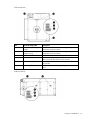
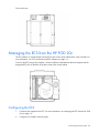
Facility chilled water sensors
Five sensors are located on the facility chilled water supply and return pipes. These sensors report data to the
ECS.
Item
Component
Description
1
Return water flow sensor
Detects the water flow rate for the chilled water return
2
Supply water pressure sensor
Detects the water pressure for the chilled water supply
3
Return water pressure sensor
Detects the water pressure for the chilled water return
4
Supply water temperature sensor Detects the water temperature for the chilled water supply
5
Return water temperature sensor
Detects the water temperature for the chilled water return
Facility connections to ECS
You can connect your facility to the ECS using the RJ45 in the demarcation box (on page 66) or cables that
are hard-wired through the connection portals on the cargo end of the HP POD 20c. The system uses Modbus
TCP/IP for communication.
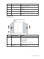
Connecting to the ECS
To connect the network to the ECS control panel, route an Ethernet cable to the appropriate RJ45 connector
inside the HP POD 20c demarcation box (on page 66).
Environmental control system 38
Front view shown
Managing the ECS from the HP POD 20c
The ECS interface is viewed directly from the ECS screen on the control cabinet door in the cold aisle. For
more information, see "ECS touchscreen and EPO indicators (on page 19)."
To access the ECS using a host computer, connect an Ethernet cable between the host computer and the
designated ECS jack on the back of the door inside of the control cabinet.
Configuring the ECS
1.
Connect a host computer to the ECS. For more information, see "Managing the ECS from the HP POD
20c (on page 39)."
2.
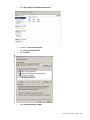
Configure your computer network groups:
Environmental control system 39
a. Select Start>Control Panel>Network Connections.
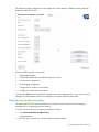
b. Double-click Local Area Connection.
c.
Select Internet Protocol (TCP/IP).
d. Click Properties.
e. Select Use the following IP address.
Environmental control system 40
f.
Enter the new IP address. Be sure to specify an IP address in the same network group as the ECS
controller. By default, the ECS controller uses 192.168.20.1. The IP address for your computer can
include any number in the group from 2 to 254.
g. Click OK.
3.
Click OK to save changes and close the TCP/IP Properties screen.
4.
Click OK to close the Local Area Connections Properties screen.
Logging in remotely to the ECS
Before you can log in remotely, you must do the following:
•
Add the PLC to a network.
•
Obtain a username and password.
•
Obtain the static IP address of the PLC. For more information, see "Locating the ECS IP addresses (on
page 42)."
Use the remote desktop application to log in to the ECS remotely:
1.
On the remote computer, select Start> All Programs> TightVNC> TightVNC Viewer.
The TightVNC window appears.
Environmental control system 41
2.
In the TightVNC Server field, enter the IP address for the PLC.
3.
Click Connect.
4.
In the User name field, enter the user name.
IMPORTANT: When logging in to the Remote Desktop, the default user name is
Administrator and the default password is HPINVENT.
5.
Click OK.
Locating the ECS IP addresses
IMPORTANT: The ECS has three NIC addresses: 10.10.10.1, 10.10.10.2, and an IP address
that is set up by the customer for external communication.
The PLC must be connected to locate the IP address for each NIC. For more information, see "Managing the
ECS from the HP POD 20c (on page 39)."
To locate the ECS IP address:
1.
Select Start>Run.
2.
Enter ipconfig.
The IP address appears.
-or1.
Select Start>Network and Sharing Center.
2.
Right-click Local Area Network.
3.
Click the Support tab.
The IP address appears.
Environmental control system 42
Password protection
The ECS has two levels of access control:
•
Customer
•
Service
The following screens are available using the customer-level password:
•
Overview screen ("Status Overview screen" on page 47)
•
Status Overview screen (on page 47)
•
Basic System Configuration screen (on page 47)
CAUTION: Making changes to the ECS in the service-level area can cause the cooling system
components to fail. Only allow authorized, qualified, and trained personnel to change
configuration settings in the service-level area of the ECS.
The following screens require the service-level password:
•
Advanced System Configuration screen (on page 52)
•
Controller Settings screen (on page 55)
Navigating the ECS interface
The ECS interface provides information for several environmental and access control conditions that can be
monitored and configured from the ECS touchscreen.
To navigate to specific screens from the Overview screen ("Status Overview screen" on page 47), select the
button for the appropriate screen.
CAUTION: Making changes to the ECS in the service-level area can cause the cooling system
components to fail. Only allow authorized, qualified, and trained personnel to change
configuration settings in the service-level area of the ECS.
IMPORTANT: Depending on the ECS configuration, the ECS numbers and screens might vary.
Environmental control system 43
Item
Button
Description
1
Zone (#) power
supply status
Navigates directly to the Power Details screen for
the specified Zone (#)
2
Fan Bank Output Navigates directly to the Fan Control Detail screen
for the specified Zone (#)
3
Enter Password
•
•
4
System
status/reset
Alarms
Enter customer level password—Navigates
directly to the Basic System Configuration
screen (on page 47)
Enter service level password—Navigates
directly to the Advanced System
Configuration screen (on page 52) or the
Controller Settings screen (on page 55)
Resets existing alarm conditions and navigates
directly to the System Status screen
Logging in to the ECS touchscreen
To log in to the ECS touchscreen:
1.
From the Overview screen, click Enter Password.
A keypad appears.
Environmental control system 44
2.
Enter your ECS password.
3.
Click OK.
Overview screen
The Overview screen appears upon activation of and displays an overview of the ECS components and the
status of each component.
The Overview screen displays the following information.
Information
Description
EPO system status
Indicates the status of the EPO system:
•
•
•
B—The EPO system is non-operational and
does not initiate during events that normally
trigger an EPO.
T—The EPO system is in test mode and does
not initiate during events that normally
trigger an EPO.
A—The EPO system is armed and
operational.
Average voltage, current,
and power drawn on the A
and B busways
Indicates electrical usage
Relative humidity
Indicates the relative humidity percentages from
each of the humidity sensors
Environmental control system 45
Information
Description
Fan speed
Indicates the fan bank speed percentage
Hot aisle temperature
Indicates the average temperature in the hot aisle
System status
Indicates the status of the ECS system:
•
•
Green—All components within the ECS
system are operating within normal
parameters, and there are no active ECS
alarms.
Red—One or more of the ECS components is
indicating an alarm condition.
Manual mode indicators for Indicates if the fans and dampers are running in
manual mode
fans and dampers
Indicates whether an access door is open or
Door access indicators
closed
Average cooling system
performance data
Indicates cooling system sensor averages
Differential pressure values
Indicates the differential pressure values from
each of the differential pressure zones between
the hot aisle and the cold aisle
The ECS component icon colors indicate the component status:
•
Green—No alarm conditions exist and the component is operating within normal parameters.
•
Red—An alarm condition for that component exists.
•
Bold numbering on a yellow background—An instrument reading is outside of the alarm limits.
For more information about alarm conditions, see "ECS alarms (on page 57)."
Environmental control system 46
Status Overview screen
The Status Overview screen displays the status of all system component alarms. For more information about
the alarms, see "ECS alarms (on page 57)."
The ECS component icon colors indicate the component status:
•
Green—No alarm conditions exist and the component is operating within normal parameters.
•
Red—An alarm condition for that component exists or the component failed.
Basic System Configuration screen
IMPORTANT: The ECS parameters must only be set by qualified service personnel.
Environmental control system 47
The Basic System Configuration screen displays the basic alarm parameters, humidifier control, and fan
controls. The configured parameters are only used to trigger an ECS alarm. The parameters listed on this
screen do not configure the cooling system.
You can select and configure the following parameters:
•
Cold aisle temperature alarm
•
Hot aisle temperature alarm
•
Humidity alarm
•
Differential pressure alarm
•
Differential pressure filter alarm
•
Chilled water supply pressure
•
Chilled water supply temperature
•
Chilled water return temperature
•
Chilled water return pressure
You must select Save to store the parameter changes in the system configuration file. If you do not save your
changes, the old parameters stored in the configuration file reload when the system starts.
Configuring the chilled water supply temperature alarm parameters
The current temperature parameters appear on the related buttons.
Environmental control system 48
To configure the chilled water supply low temperature alarm parameters:
1.
Select Chilled Water Supply Low Alarm Temperature.
A keypad appears.
2.
Enter a temperature alarm parameter.
3.
Select Save to store the new parameters in the system configuration file.
To configure the chilled water supply high temperature alarm parameters:
1.
Select Chilled Water Supply High Alarm Temperature.
A keypad appears.
2.
Enter a temperature alarm parameter.
3.
Select Save to store the new parameters in the system configuration file.
Configuring the chilled water return temperature alarm parameters
The current temperature parameters appear on the related buttons.
To configure the chilled water return low temperature alarm parameters:
1.
Select the Chilled Water Return Low Alarm Temperature.
A keypad appears.
2.
Enter a temperature alarm parameter.
3.
Select Save to store the new parameters in the system configuration file.
To configure the chilled water return high temperature alarm parameters:
1.
Select the Chilled Water Return High Alarm Temperature.
A keypad appears.
2.
Enter a temperature alarm parameter.
3.
Select Save to store the new parameters in the system configuration file.
Configuring the chilled water supply pressure alarm parameters
The current differential pressure parameters appear on the related buttons.
To configure the chilled water supply pressure low alarm parameters:
1.
Select Chilled Water Supply Pressure Low Alarm.
A keypad appears.
2.
Enter a differential pressure alarm parameter.
3.
Select Save to store the new parameters in the system configuration file.
To configure the chilled water supply pressure high alarm parameters:
1.
Select Chilled Water Supply Pressure High Alarm.
A keypad appears.
2.
Enter a differential pressure alarm parameter.
3.
Select Save to store the new parameters in the system configuration file.
Environmental control system 49
Configuring the chilled water supply pressure alarm parameters
The current chilled water return pressure alarm parameters appear on the related buttons.
To configure the chilled water return pressure low alarm parameters:
1.
Select Chilled Water Return Pressure Low Alarm.
A keypad appears.
2.
Enter a chilled water return pressure alarm parameter.
3.
Select Save to store the new parameters in the system configuration file.
To configure the chilled water return pressure high alarm parameters:
1.
Select Chilled Water Return Pressure High Alarm.
A keypad appears.
2.
Enter a chilled water return pressure alarm parameter.
3.
Select Save to store the new parameters in the system configuration file.
Configuring the humidity alarm parameters
The current relative humidity parameters appear on the related buttons.
To configure the low humidity parameters:
1.
Select the Humidity Low Alarm.
A keypad appears.
2.
Enter a humidity alarm parameter.
3.
Select Save to store the new parameters in the system configuration file.
To configure the high humidity parameters:
1.
Select the Humidity High Alarm.
A keypad appears.
2.
Enter a humidity alarm parameter.
3.
Select Save to store the new parameters in the system configuration file.
Configuring the cold aisle temperature alarm parameters
The current temperature parameters appear on the related buttons.
To configure the cold aisle low temperature alarm parameters:
1.
Select Cold Aisle Low Alarm Temperature.
A keypad appears.
2.
Enter a temperature alarm parameter.
3.
Select Save to store the new parameters in the system configuration file.
To configure the cold aisle high temperature alarm parameters:
1.
Select Cold Aisle High Alarm Temperature.
A keypad appears.
2.
Enter a temperature alarm parameter.
3.
Select Save to store the new parameters in the system configuration file.
Environmental control system 50
Configuring the hot aisle temperature alarm parameters
The current temperature parameters appear on the related buttons.
To configure the hot aisle low temperature alarm parameters:
1.
Select Hot Aisle Low Alarm Temperature.
A keypad appears.
2.
Enter a temperature alarm parameter.
3.
Select Save to store the new parameters in the system configuration file.
To configure the hot aisle high temperature alarm parameters:
1.
Select Hot Aisle High Alarm Temperature.
A keypad appears.
2.
Enter a temperature alarm parameter.
3.
Select Save to store the new parameters in the system configuration file.
Configuring the differential pressure alarm parameters
The current differential pressure parameters appear on the related buttons.
To configure the low differential pressure parameters:
1.
Select Difference Pressure Low Alarm.
A keypad appears.
2.
Enter a differential pressure alarm parameter.
3.
Select Save to store the new parameters in the system configuration file.
To configure the high differential pressure parameters:
1.
Select Difference Pressure High Alarm.
A keypad appears.
2.
Enter a differential pressure alarm parameter.
3.
Select Save to store the new parameters in the system configuration file.
Configuring the differential pressure alarm parameters
The current differential pressure filter parameters appear on the related buttons.
To configure the low differential pressure filter parameters:
1.
Select Differential Pressure Filter Low Alarm.
A keypad appears.
2.
Enter a differential pressure alarm parameter.
3.
Select Save to store the new parameters in the system configuration file.
To configure the high differential pressure filter parameters:
1.
Select Differential Pressure Filter High Alarm.
A keypad appears.
2.
Enter a differential pressure alarm parameter.
3.
Select Save to store the new parameters in the system configuration file.
Environmental control system 51
Setting the humidifier control
HP recommends leaving the fans in AUTO mode during normal operation.
To set the humidifier control:
1.
Select Auto/Manual.
2.
Select Save to store the new parameters in the system configuration file.
To configure the humidifier setpoint percentage:
1.
Select Humidifier Setpoint (%).
A keypad appears.
2.
Select Save to store the new parameters in the system configuration file.
Setting the fan controls for each fan control zone
The current fan speed appears on each fan control zone.
HP recommends leaving the fans in AUTO mode during normal operation.
To configure the fan speed:
1.
Select the Auto/Manual in the fan control zone you want to change.
2.
If you are setting the fan to Manual mode, select the fan speed (0-4) by pressing the corresponding
number.
3.
Select Save to store the new parameters in the system configuration file.
Advanced System Configuration screen
You can only access this screen after you have entered a service-level password.
Environmental control system 52
The Advanced System Configuration screen displays fan current setpoints, calibration options, and other
details about the HP POD 20c.
Perform the following tasks on this screen:
•
Calibrate the flowmeter.
•
Calibrate the chilled water and differential pressure sensors.
•
View the power configuration.
•
Set the logging configuration.
•
Configure the HP POD 20c serial number.
•
Configure the switchboard serial number.
You must select Save to store the parameter changes in the system configuration file. If you do not save your
changes, the old parameters stored in the configuration file reload when the system starts.
Setting the start-up alarm reset delay
This option gives the POD time (in seconds) during a start-up to achieve at least minimum operating
parameters prior to registering an alarm condition.
To set the amount of time prior to registering an alarm condition:
1.
Select Reset alarms after startup time (sec).
A keypad appears.
2.
Enter the time in seconds you want the alarms to reset after startup.
Environmental control system 53
3.
Select Save to store the new parameters in the system configuration file.
Calibrating the flowmeter
This option enables flow rate calibration based on the value of a calibrated flow meter.
To calibrate the flowmeter:
1.
Power down the HP POD 20c. For more information, see "Power down procedure (on page 73)."
2.
Select Flowmeter Calibration Factor.
A keypad appears
3.
Enter the calibration factor.
4.
Select OK.
5.
Select Save to store the new parameters in the system configuration file.
Calibrating the differential pressure sensors
This option is available only when all fans and the IT load are powered off and there is no air flowing inside
the HP POD 20c.
To calibrate the chilled water pressure sensors:
1.
Power down the POD. For more information, see "Power down procedure (on page 73)."
2.
Set the fan speed for each fan control zone to Manual mode and 0% fan speed. For more information,
see "Setting the fan controls for each fan control zone (on page 52)."
3.
Open the doors for five minutes to equalize the pressure between the hot and cold aisles.
4.
Select Calibrate Differential Pressure Sensors.
5.
Select Save.
6.
Set the fan speeds to Auto mode.
Setting the logging configuration
To log the power configuration information:
1.
Select Logging On/Off.
2.
Select Save to store the new parameters in the system configuration file.
To set the log interval:
1.
Select Log interval (sec).
A keypad appears.
2.
Select Save to store the new parameters in the system configuration file.
To set the amount of time to keep power configuration log files:
1.
Select Keep Log Files For (Months).
A keypad appears.
2.
Select Save to store the new parameters in the system configuration file.
Environmental control system 54
Setting the switchboard serial number
To identify the switchboard connected to the HP POD 20c, set the switchboard serial number in the ECS:
1.
Select Switchboard S/N.
A keypad appears.
2.
Enter the switchboard serial number.
3.
Select Save to store the new parameters in the system configuration file.
Setting the HP POD 20c serial number
If multiple HP POD 20c units are connected to the same facility BMS, enter each HP POD 20c serial number
to monitor and display each HP POD 20c ECS independently through the facility BMS.
To set the HP POD 20c serial number in the ECS:
1.
Select POD S/N.
A keypad appears.
2.
Enter the HP POD 20c serial number. For more information, see "Parts and part number identification
(on page 8)."
3.
Select Save to store the new parameters in the system configuration file.
Loading default settings
This option enables you to revert the ECS system back to the factory settings.
CAUTION: Pressing this button causes all customized ECS settings to be lost.
To load the default settings:
1.
Select Load Default Settings.
2.
Select OK.
Controller Settings screen
You can only access this screen after you have entered a service-level password.
Environmental control system 55
The Controller Settings screen displays the control setpoints for each major system component.
You can set the following configuration options:
•
PI settings temperature
•
PI settings pressure
You must select Save to store the parameter changes in the system configuration file. If you do not save your
changes, the old parameters stored in the configuration file reload when the system starts.
Item
Description
Temperature setpoint (hot
aisle)
Sets the temperature setpoint for the hot aisle
Pressure setpoint
Sets the pressure setpoint
PI parameter P
Proportion gains influence the rate of change in the position of the flow control
valve or the fan speed in order to reach the pre-determined setpoints
PI parameter I
Integral gains influence the rate of change in the position of the flow control valve
or the fan speed in order to reach the pre-determined setpoints.
PI integration time
Used by the low pass filter to even the measurement values out
Environmental control system 56
I/O Overview screen
The I/O Overview screen displays the status of inputs and outputs of all major system component alarms. For
more information about the alarms, see "ECS alarms (on page 57)."
The ECS component icon colors indicate the component status:
•
Green—No alarm conditions exist and the component is operating within normal parameters.
•
Red—An alarm condition for that component exists or the component failed.
ECS alarms
The alarms pertaining to the health of the HP POD 20c and its components are relayed through the ECS.
Alarm
Meaning
Fan failure
One of the fans is not working. See the HP Performance Optimized Datacenter
20c Maintenance and Service Guide or contact
HP service if you are still within your service
contract.
Solution
Sensor failure
One of the sensors is not
working.
See the HP Performance Optimized Datacenter
20c Maintenance and Service Guide or contact
HP service if you are still within your service
contract.
Environmental control system 57
Alarm
Meaning
Solution
Leak detection
The drain pan sensor detects
water in the pan.
See the HP Performance Optimized Datacenter
20c Maintenance and Service Guide or contact
HP service if you are still within your service
contract.
Change filter
The return air filters are full.
Replace the return air filters. For more
information, see the HP Performance Optimized
Datacenter 20c Maintenance and Service
Guide.
High temperature
The cold aisle temperature has 1
surpassed the setpoint
temperature.
2
Verify that you have water flowing into your
HP POD 20c and the fans are operating.
Contact HP service if you are still within your
service contract.
Low temperature
The cold aisle temperature is
too low.
Verify that all components are operating
normally.
Contact HP service if you are still within your
service contract.
1
2
EPO
The EPO system activates and
the HP POD 20c shut down.
1
2
Differential pressure
The difference in pressure
1
between the hot and cold aisles
is above the setpoints.
2
Follow the emergency procedures for your
facility.
After the emergency is cleared, reset the
EPO and other HP POD 20c systems.
Verify that the cold/hot aisle differential
pressures are within the setpoints.
Contact HP service if you are still within your
service contract.
Safety and access control alarms
Alarms pertaining to the safety of the HP POD 20c are (optionally) relayed through your building fire and
access control dispatch.
Alarm
Meaning
Solution
Fire alarm*
The HP POD 20c detected a fire.
Activate the EPO. Follow the emergency
procedures for your facility.
Access control alarm
(optional)
An access control breach occurred.
Follow the emergency procedures for your
facility.
EPO
The EPO system activated and the HP Follow the emergency procedures for your
POD 20c shut down.
facility.
*The fire alarm is relayed to your building fire and access control dispatch only if you have connected your facility to the
fire box (on page 67).
Environmental control system 58
Cooling system
HP POD 20c cooling system theory of operation
CAUTION: Using contaminated supply water can cause decreased cooling capacity or
disruption in service. The supply water must meet the guidelines stated in the HP Performance
Optimized Datacenter 20c Site Preparation and Requirements Guide. Damage caused by
contaminated supply water is not covered by the warranty.
The HP POD 20c has six heat exchangers configured in three zones that maintain temperature and cool the
equipment installed in the HP POD 20c. The HP POD 20c receives chilled water from your facility, cycles the
water through the heat exchangers to cool the air, and then the fans circulate the cool air throughout the HP
POD 20c.
A predetermined differential pressure setpoint between the hot aisle and the cold aisle is factory set. Do not
alter the setpoint without consulting HP. The speed of the fan units is regulated to maintain the differential
pressure between the hot aisle and the cold aisle. For more information, see "Fans (on page 62)."
The HP POD 20c chilled water flow rate is not regulated by the ECS system. Site control over chilled water
flow rate is necessary to allow 454 lpm (120 gpm*).
For more information on the cooling system, see the HP POD 20c Maintenance and Service Guide.
Measurement is in US gallons per minute.
*
Water supply temperature
The temperature of the water supplied to the HP POD 20c must be 13ºC to 24ºC (55ºF to 75ºF). Freezing
water can cause a blockage and damage to the POD.
Cooling system 59
The minimum HP server inlet temperature is 10°C (50°F). For non-HP equipment, consult the documentation
for that equipment.
Water quality requirements and specifications
The following are the water quality requirements and specifications:
•
Closed-loop water must not contain any lime scale deposits or loose debris.
•
The temperature of the chilled water supplied to the HP POD 20c must be 12ºC to 24ºC (55ºF to 75ºF).
CAUTION: Freezing water can cause a blockage and damage to the unit. In outside locations
that are subject to freezing temperatures, an additive such as glycol might be necessary to lower
the freezing point. However, since the heat transfer potential of water with glycol is lower, the HP
POD 20c must be de-rated accordingly.
IMPORTANT: The chilled water system piping and heat exchangers must be drained completely,
and then purged using compressed air when storing or transporting at or below freezing
temperatures.
IMPORTANT: Operating the chilled water system at the higher end of the acceptable range
decreases the overall thermal capacity of the POD.
Acceptable water quality specifications
Water must be maintained per the following acceptable water quality standards.
Parameter
Range
pH
8.0–10
Specific conductance at 25ºC (77ºF) 10–2500 µmhos
150–1000 ppm
Alkalinity ("M" as CaCO3)
Sulfur (SO4)
Chloride (Cl)
Hardness (CaCO3)
Calcium hardness (CaCO3)
Magnesium hardness (CaCO3)
0–150 ppm
0–100 ppm
0–350 ppm
0–200 ppm
0–150 ppm
Copper (Cu)
< 0.20 ppm
Iron (Fe)
< 3.0 ppm
Aluminum (Al)
< 0.50 ppm
Sodium (Na)
0–1000 ppm
Silica (SiO2)
0–150 ppm
Zinc (Zn)
< 1.0 ppm
Manganese (Mn)
< 0.1 ppm
Phosphate Ortho- (PO4)
< 3 ppm
Bacteria
< 1000 CFU/ml
Suspended solids
< 10 ppm
If your water is out of range, consult a water quality expert.
The following table describes the chilled water system specifications for the HP POD 20c.
Cooling system 60
Feature
Specification
Facility input temperature to the HP POD
20c
12º to 24ºC (55º to 75ºF)
Max design pressure
1,034 kPa (150 psi)
HP POD 20c pressure drop
172.4 kPa (25 psi)
HP POD 20c water flow rate
454 lpm (120 gpm*)
Chilled water supply and return
connections
Two DIN PN16 DN80 flanges
*Measurement is in US gallons per minute.
Cooling system components
Each of the three heat exchanger area access hatches are rated NEMA 3R for outdoor use. The exterior of
the hatches are coated with a durable finish to protect against corrosion. The access hatches are located on
the roof of the POD. The heat exchangers can be accessed from the roof of the POD by removing one of the
six access hatches.
Top view shown
Item
Component
Description
1
Heat exchangers
Uses chilled facility water to cool the air in the HP POD 20c
2
Chilled water supply
header
Provides cooled chilled water from the site chilled water system to the heat
exchangers
3
Chilled water return
header
Provides heated chilled water to the return site chilled water system
Cooling system 61
End view shown
Item
Component
Description
1
Heat exchanger
Uses chilled facility water to cool the air in the HP POD 20c
2
Drain pan sensor
Detects excessive amounts of condensate in the drain pan and sends an alarm
signal to the ECS
3
Drain pan
Collects and directs heat exchanger condensate to the condensate drain
4
Condensation drain
Removes condensation from the drain tray to the exterior of the HP POD 20c
5
Header drain pan
Provides leak detection for the chilled water supply and the chilled water
supply return
Fans
HP POD 20c fans operate at variable speeds to maintain the following setpoints programmed in the ECS. The
setpoints are maintained in the following order:
1.
Differential pressure setpoint between the hot and cold aisles
2.
Hot aisle temperature setpoint
The fan speed adjusts to maintain both setpoints. Do not manually adjust the fan speed.
IMPORTANT: HP recommends leaving the fans in AUTO mode during normal operation.
Cooling system 62
Depending on the IT equipment installed in your HP POD 20c, you can choose to change both default
parameters to improve the overall efficiency of your system. To discuss the effects of changing these
parameters for your specific HP POD 20c, contact HP ("HP contact information" on page 78).
Item
Component
Quantity
Description
1
Fan tray assemblies
3 banks of 6 (18
Circulates cool air from the heat exchangers
total) fans per zone throughout the HP POD 20c
2
Fan control and power
supply assembly
3
Provides fan speed control, status, and DC power
for the fans
Condensation management
CAUTION: To maintain accurate environmental conditions inside the HP POD 20c, do not leave
the HP POD 20c doors open during operation.
The heat exchanger drip trays collect condensation that forms on the heat exchangers. This collected
condensation drains out of the HP POD 20c through the heat exchanger condensate drains. HP recommends
connecting the condensate drains on the HP POD 20c to a facility drain to prevent collection of water near
the HP POD 20c.
The HP POD 20c has two 3.18 cm (1.25 in) condensate drain outlets located at both ends of the hot aisle of
the HP POD 20c. The drain outlets are directly connected to the heat exchanger drip trays. The HP POD 20c
main supply and return line is connected to the condensate drain line.
To avoid excessive buildup of condensation and to conserve energy, raise the cooling water temperature to
above the dew point to manage condensation while maintaining the necessary cooling capacity.
Drains
WARNING: Water that drains around the HP POD 20c can cause a potential slip hazard. Use
caution where slip hazards are present.
Cooling system 63
HP recommends connecting the condensate and humidifier drains from the HP POD 20c to a facility drain to
prevent collection of water near the HP POD 20c. For more information on drain connections, see the HP
Performance Optimized Datacenter 20c Site Preparation and Requirements Guide.
Hot aisle drains
Heat exchanger condensate drains
Side view shown
Water from natural condensation forms. Condensation from the heat exchangers flows to one of the two
condensation drains located at each end of the hot aisle.
IMPORTANT: You might need to connect the HP POD 20c condensate drains directly to the local
storm or sanitary drain, depending on the local jurisdictional requirements.
Cold aisle drains
Item
Component
Description
1
Chilled water supply and return Drains water from the chilled water supply and return header drip
header drain
pans in the event a leak develops
2
Humidifier drain
Drains water from the humidifier
Cooling system 64
IMPORTANT: The humidifier drain contains concentrated impurities due to the humidification
process and is extremely hot. You might need to connect this drain and the supply head drains
directly to a local storm or sanitary drain, depending on the local jurisdictional requirements.
Leak detection
The HP POD 20c includes six heat exchanger condensate sensors. Three sensors are located in the drain
trays below each set of heat exchangers, and three sensors are located in the header drain pans.
There should be no water in the chilled water supply and return header drain pan, and the drain pan should
always remain dry.
Some amount of condensation water can always be expected in the heat exchanger drain pans. If an
excessive amount of condensation water accumulates in a drain pan, an alarm is triggered and sent through
the HP POD 20c ECS, indicating a possible leak.
For more information on leak detection, see the HP Performance Optimized Datacenter 20c Maintenance
and Service Guide.
Cooling system 65
IT networking and communications
Networking
Connecting the HP POD 20c to the facility network is a vital part of ensuring the functionality of the various
communication systems. See the HP Performance Optimized Datacenter Networking Guide for more
information.
All connections are the responsibility of the customer. For configuration and installation instructions, consult
with HP.
Connection portals
Networking and connection portals are located on the cargo end of the HP POD 20c. Each HP POD 20c has
six 6.35-cm (2.5-in) portals for customer data connection. These portals are provided to allow the customer
to make connections to the HP POD 20c.
End view shown
Demarcation box
The following communication connections between the customer facility and the HP POD 20c are made
through the demarcation box:
•
ECS communication
•
Access control communication
•
Telephone
IT networking and communications
66
Front view shown
You must make the connections between the facility and the HP POD 20c. For configuration and installation
instructions, consult with HP.
Fire box
The communication connections between the fire system and the HP POD 20c are made through the fire box.
Front view shown
You must make the connections between the facility and the HP POD 20c. For configuration and installation
instructions, consult with HP.
IT networking and communications
67
Optional components
Fire protection system
The fire protection system is a HP POD 20c self-contained system, with no connection to your ECS. The fire
protection system consists of 3M Novec 1230, a clean agent fire suppressant, eliminating the need for
additional water to be connected to the HP POD 20c in case of a fire emergency.
Humidifier
The humidifier option maintains the humidity in the HP POD 20c within a set range according to ASHRAE
standards.
IMPORTANT: The humidifier is required if you want the POD to remain within ASHRAE
recommended or allowable standards.
Maintaining the humidity helps to minimize static electricity within the HP POD 20c.
Side view shown
Controlled access
The HP POD 20c controlled access option adds magnetic locks and 12-digit keypads to the hot and cold
aisle dynamic doors. This option enables you to provide controlled access to the hot and cold aisle without
the need for keys.
Optional components 68
Power up procedure
Standard HP POD 20c power up procedure
This procedure is for your reference only and assumes that the POD is fully commissioned and powered up
by HP before being turned over to you.
Before beginning the power up procedures in this section, verify that the POD is not in operation and that the
internal ambient temperature of the POD is greater than 10ºC (50ºF). If the internal ambient temperature of
the POD is less than 10ºC (50ºF), see "Cold weather HP POD 20c power up procedure (on page 70)."
This process helps to ensure personnel safety during the electrical start up of the HP POD 20c.
WARNING: To avoid risk of personal injury or loss of life, do not open an energized POD
electrical cabinet without an energized work permit and appropriate PPE.
Power up checklist
Site electrical
Verify that all site POD feeder supply breakers are open.
Site mechanical
Verify that the POD supply and return isolation valves are closed.
POD mechanical
Verify that the POD chilled water return butterfly isolation valve is open.
POD electrical
•
Hot aisle—Verify that all IT power drop box breakers on the power tap boxes are open.
•
Cold aisle:
a. Close all breakers and fuses within the control cabinet.
b. Close and latch the ECS cabinet.
c.
Position the EPO system (on page 18) to Armed (White) or Bypass (Green).
d. Verify that all EPO activation buttons are in the reset position (not depressed).
e. Position the 24V DC power switch to On.
•
Main power feed cabinet:
a. Close main power feed breakers A and B.
b. Verify power surge fuses are installed.
•
House power and critical IT power cabinets:
a. Close all fuses in the house power and critical IT power cabinets.
b. Close all non-spare breakers in the house power and critical IT power cabinets.
c.
Close and lock both house power and transformer cabinet doors.
Power up procedure
69
Standard power up procedure
Perform the following procedures in the exact order in which they are listed.
Site electrical
Close all POD site power feeder breakers and monitor for any effects that are not standard.
Site chilled water
1.
Open the POD supply chilled water isolation valve.
2.
If necessary, vent the air from the chilled water return header.
3.
Open the POD return chilled water isolation valve.
4.
Verify that audible flow noises are present.
ECS and EPO
Verify the following on using the ECS touchscreen and EPO indicators:
•
The ECS panel is operational and displays the user interface.
•
The POD lighting is operational.
•
The EPO system is set to Armed (White) or Bypass (Green).
POD operation
1.
On the ECS touchscreen, verify that all system components are operational (green) and no alarm
conditions exist.
2.
On the ECS touchscreen, verify that all system parameters are operating normally.
3.
On the ECS touchscreen, verify that the POD chilled water flow rate is established on the flow rate
indicator.
4.
In the hot aisle, close the power drop box breakers for each rack and ensure that the IT equipment is
operating.
5.
In the cold aisle, monitor the flow control position, chilled water flow, and POD temperatures.
6.
Wait five minutes to allow the system to stabilize.
The HP POD 20c is now fully operational and the control system automatically controls the fan and the flow
control valve position.
Cold weather HP POD 20c power up procedure
This procedure is for your reference only and assumes that the POD was fully commissioned and powered up
by HP before being turned over to you.
Before beginning the power up procedures in this section, verify that the POD is not in operation and that the
internal ambient temperature of the POD is less than 10ºC (50ºF). If the internal ambient temperature of the
POD is greater than 10ºC (50ºF), see "Standard HP POD 20c power up procedure (on page 69)."
IMPORTANT: The minimum acceptable inlet temperature for IT equipment is 10ºC (50ºF).
Power up procedure
70
This process helps to ensure personnel safety during the electrical start up of the HP POD 20c.
WARNING: To avoid risk of personal injury or loss of life, do not open an energized POD
electrical cabinet without an energized work permit and appropriate PPE.
Cold weather power up checklist
Site electrical
Open (verify open) all site POD feeder supply breakers.
Site mechanical
Verify that the POD supply and return isolation valves are closed.
POD mechanical
Open (verify open) POD chilled water return butterfly isolation valve.
POD electrical
•
Hot aisle—Verify that all IT power drop box breakers on the power tap boxes are open.
•
Cold aisle:
a. Close all breakers and fuses within the control cabinet.
b. Close and latch the ECS cabinet.
c.
Position the EPO system (on page 18) to Armed (White) or Bypass (Green).
d. Verify that all EPO activation buttons are in the reset position (not depressed).
e. Position the 24V DC power switch to On.
•
Main power feed cabinet:
a. Close main power feed breakers A and B.
b. Verify power surge fuses are installed.
•
House power and critical IT power cabinets:
a. Close all fuses in the house power and critical IT power cabinets.
b. Close all non-spare breakers in the house power and critical IT power cabinets.
c.
Close and lock both house power and transformer cabinet doors.
Standard power up procedure
Perform the following procedures in the exact order in which they are listed.
Site electrical
Close all POD site power feeder breakers and monitor for any effects that are not standard.
ECS and EPO
Verify the following using the ECS touchscreen and EPO indicators:
•
The ECS panel is operational and displays the user interface.
•
POD lighting is operational.
Power up procedure
71
•
The EPO system is set to Armed (White) or Bypass (Green).
Site chilled water
1.
Open the POD supply chilled water isolation valve.
2.
If necessary, vent the air from the chilled water return header.
3.
Open the POD return chilled water isolation valve.
4.
Verify audible flow noises are present.
IMPORTANT: To allow the POD ambient temperature to be raised in a controlled manner, open
the chilled water supply and return isolation valves to enable 454.25 lpm (120 gpm*) at a
temperature of 13ºC to 24ºC (55ºF to 75ºF) to flow through the heat exchangers and allow the
circulation fans to bring the ambient temperature to >10ºC (50ºF).
• Portable heaters can be used to disperse supplemental heat uniformly throughout the POD.
• Electric portable heaters must be powered from an outside source.
Measurement is in US gallons per minute.
*
POD heating procedure
1.
On the ECS touchscreen, verify that all system components are operational (green) and no alarm
conditions exist.
2.
On the ECS touchscreen, verify that the POD chilled water flow rate is established on the flow rate
indicator.
3.
Take manual control of the fans to the preferred speed to circulate the warm air in the POD.
4.
Determine the hot aisle temperature:
5.
o
If the hot aisle temperature is at or above -25ºC (13ºF), continue to the next step.
o
If the hot aisle temperature is not at or above -25ºC (13ºF), continue monitoring the hot aisle
temperature until it reaches -25ºC (13ºF) and continue this warm up procedure for 60 minutes
before proceeding.
Record the cold aisle temperature that displays on the ECS. The recorded temperature is the starting
temperature of the servers.
IMPORTANT: With non-operating servers, the temperature rate of change should not exceed
20ºC (68ºF) per hour. At higher elevations, the rate of change must be reduced by 1ºC (34ºF) for
every 305 m (1,000 ft) above sea level.
6.
When the cold aisle temperature reaches a minimum of 10ºC (50ºF), maintain the temperature for at
least 60 minutes before proceeding.
CAUTION: Do not continue the start up procedures unless the fans are in AUTO mode.
7.
Set all fans to AUTO mode.
POD operation
1.
In the hot aisle, close the power drop box breakers for each rack and ensure that the IT equipment is
operating.
2.
In the cold aisle, monitor the flow control position, chilled water flow, and POD temperatures.
Power up procedure
72
3.
Wait five minutes to allow the system to stabilize.
The HP POD 20c is now fully operational and the control system automatically controls the fans and the flow
control valve position.
Power down procedure
1.
Power down all IT equipment.
2.
Open all POD power drop box breakers.
3.
Monitor the system parameters and allow the POD to cool to an acceptable temperature. Be sure that
the cold aisle temperature does not fall below 10°C (50°F.)
4.
Close the POD return chilled water isolation valve.
5.
Close the POD supply chilled water isolation valve.
6.
Open the POD main power feed breakers.
7.
Unlock the POD house power and critical IT power cabinets.
8.
Open all breakers in the POD power cabinets A and B.
9.
Unlock the POD main power feed cabinet.
10.
Open all breakers in the POD main power feed cabinet.
The HP POD 20c is now powered down and all breakers are ready for standard or cold weather power up.
Power up procedure
73
Specifications
General HP POD 20c specifications
Features
Specifications
Overall dimensions
•
•
•
Height—3.05 m (10 ft)
Length—6.10 m (20 ft)
Width—2.43 m (7.97 ft)
Weight1
•
•
Empty—7,711 kg (17,000 lb)
Maximum fully loaded—22,680 kg (50,000 lb)
Maximum power2
288 kW
Power input voltage
380-415 V, 3-phase, 4-wire
Power input current
2 x 320 A electrical busways 3-phase, 4-wire feeders
Maximum rack quantity
10 racks
Rack Units (RU) per rack
50 RU
Rack Units (RU) total
500 RU
Average capacity per rack (kW)
30 kW
Peak rack capacity
69 kW
Voltage to rack
200-240 VAC
Minimum quantity of PDUs per HP POD 20c
10 (one per rack)
Maximum quantity of PDUs per HP POD 20c
20 (two per rack)
Maximum power per PDU
30A = 17 kW; 60A = 34 kW
Network supported
•
•
•
Bulk cable pass-through-fiber
Bulk cable pass-through-copper
External rated DEMARC box
The empty weight includes the HP POD 20c structure, empty racks, PDUs, and drop boxes. It does not include IT
equipment.
2
The maximum power depends on the exact installation and power configuration in your POD. The HP POD 20c is
electrically limited to 288 kW.
1
Electrical specifications
Electrical busway system information
Feature
Specification
Number of busways
2
Frequency
50-60 Hz
Amps (per busway)
200 A
Voltage (per busway)
380-415 VAC Wye
Grounding
Copper
Busway configuration
3-phase + neutral + equipment ground
Specifications
74
Fire alarm panel connections
The electrical layout of the fire alarm system is as described in the schematic drawing supplied with the HP
POD 20c.
Water specifications
The following table describes the chilled water system specifications for the HP POD 20c.
Feature
Specification
Facility input temperature to the HP POD
20c
12º to 24ºC (55º to 75ºF)
Max design pressure
1,034 kPa (150 psi)
HP POD 20c pressure drop
172.4 kPa (25 psi)
HP POD 20c water flow rate
454 lpm (120 gpm*)
Chilled water supply and return
connections
Two DIN PN16 DN80 flanges
*Measurement is in US gallons per minute.
Rack specifications
Standard HP POD 20c racks (AT978A)
Feature
Specification
U height
50U
Width
54.6 cm (21.5 in)
Depth
99 cm (39 in)*
Maximum load weight
1,360.7 kg (3,000 lb)
*This specification indicates the maximum clearance for the cold aisle. Equipment cannot exceed this measurement.
Thermal and air flow performance
Maximum thermal and air flow
performance parameters
HP POD 20c specification
Air temperature—Inlet to
rack-mounted components
Dependent on IT configuration and
chilled water inlet temperature
Chilled water temperature
12°C to 24°C (55°F to 75°F)
Total rack-mounted component air
flow
Variable as required to maintain hot
aisle setpoint temperature and
dependent on IT configuration
Heat rejection capacity
300 kW
Environmental specifications
Feature
Specification
Operating temperature
-28ºC to 54ºC (-18ºF to 130ºF)
Non-operating temperature* -29ºC to 54ºC (-20ºF to 130ºF)
Specifications
75
Feature
Specification
Operating humidity
•
•
0% to 100% external
10% to 90% non-condensing internal
Non-operating humidity*
•
•
5% to 95% relative non-condensing
39ºC (102ºF) maximum wet bulb
temperature
Operating altitude
-76.2 m to 3,048 m (-250 ft to 10,000 ft)
Non-operating altitude
-76.2 m to 9,144 m (-250 ft to 30,000 ft)
*For non-operating specifications, consider the temperature of computer and IT equipment inside the HP POD 20c.
Specifications
76
Maintenance
Periodic maintenance
Perform periodic inspections to ensure that the HP POD 20c continues to perform according to design
parameters. During periodic inspections, pay special attention to electrical connections and wiring.
For more specific maintenance information, see the HP Performance Optimized Datacenter 20c
Maintenance and Service Guide.
Sample HP POD 20c maintenance schedule
For detailed maintenance information and schedules, consult with HP services.
The following table is a sample maintenance schedule for an HP POD 20c. For more detailed maintenance
information, see the HP Performance Optimized Datacenter 20c Maintenance and Service Guide.
Component to be inspected
Frequency
Electrical connections and wiring—Visual
Every 30 days
Electrical connections and wiring—Thermal scans
Every 180 days
Condensation and drainage system (leaks)—Visual
Every 30 days
Condensation and drainage system (leaks)—Functional
Every 90 days
Busway interconnects (tightened)
Every 180 days
EPO system
Every 180 days
Third-party OEM components (fire alarm and suppression system, humidifier, For more information about the
components, see the Operation
and so on)
and Maintenance manual for
the HP Performance Optimized
Datacenter 20c.
Maintenance
77
Contacting HP
Before you contact HP
Be sure to have the following information available before you call HP:
•
Active Health System log (HP ProLiant Gen8 or later products)
Download and have available an Active Health System log for 3 days before the failure was detected.
For more information, see the HP iLO 4 User Guide or HP Intelligent Provisioning User Guide on the HP
website (http://www.hp.com/go/ilo/docs).
•
Onboard Administrator SHOW ALL report (for HP BladeSystem products only)
For more information on obtaining the Onboard Administrator SHOW ALL report, see the HP website
(http://www.hp.com/go/OAlog).
•
Technical support registration number (if applicable)
•
Product serial number
•
Product model name and number
•
Product identification number
•
Applicable error messages
•
Add-on boards or hardware
•
Third-party hardware or software
•
Operating system type and revision level
HP contact information
For United States and worldwide contact information, see the Contact HP website
(http://www.hp.com/go/assistance).
In the United States:
•
To contact HP by phone, call 1-800-334-5144. For continuous quality improvement, calls may be
recorded or monitored.
•
If you have purchased a Care Pack (service upgrade), see the Support & Drivers website
(http://www8.hp.com/us/en/support-drivers.html). If the problem cannot be resolved at the website,
call 1-800-633-3600. For more information about Care Packs, see the HP website
(http://pro-aq-sama.houston.hp.com/services/cache/10950-0-0-225-121.html).
Contacting HP
78
Regulatory information
HP POD 20c regulatory compliance
The HP POD 20c complies with the following regulatory standards.
Standard
Certification level
Standard title
IEC/EN
60950
"Intertek Tested and
Certified"
•
•
IBC 2009
Designed to Comply
With the applicable
requirements
IEC/EN 60950—Standard for Safety Information Technology
Equipment, Part 1: General Requirements, Issue: 2006
IEC/EN 60950—Standard for Safety Information Technology
Equipment, Part 22: Equipment to be Installed Outdoors, Issue:
2006
2009 International Building Code, © 2010 International Code
Council, Inc.
Safety and IEC compliance
The HP POD 20c is examined, tested, and found to be in compliance with IEC/EN 60950 Part 1 and Part
22 as an Information Technology Product. For more information, see "HP POD 20c regulatory compliance
(on page 79)."
The HP POD 20c is not suitable for long-term human occupancy. The HP POD 20c is Listed as a Product that
provides service access areas for periodic maintenance and service. These areas must be used only by
owner-authorized and qualified personnel who are trained in the maintenance and service of the HP POD
20c components.
IMPORTANT: Before installing the HP POD 20c, consult your local Authorities for applicable
regulations and to review site-specific location guidelines. If needed, obtain any necessary
permits.
Additional considerations for safety and Electrical compliance are as follows:
•
The HP POD 20c is Certified as an Information Technology Product to IEC/EN 60950 Part 1 and Part
22.
•
The HP POD 20c is evaluated as a "non-inhabitable product" that provides "service access" areas for
customer-authorized, qualified, and trained service personnel.
•
The electrical connections of the HP POD 20c are evaluated as feeder connections for connection to an
existing facility, and are not suitable as "service entrance" for connection to the utility.
•
The HP POD 20c is designed for stationary installation outdoors in a Pollution Degree 3 environment,
in restricted access locations, with field wiring terminals provided for permanent supply connections.
•
The HP POD 20c meets the following ratings.
Feature
Specification
Category
Rated Overvoltage Category III
Protection
Surge protection device
Regulatory information 79
Feature
Specification
Class
Class1
Ambient temperature
2°C to 54°C (35.6°F to 129.2°F)
Relative humidity
0% to 100% humidity
•
As part of the overall certification, relevant sections of the International Building Code have been
applied as part of the design and evaluation. The current design supports wind loads up to 144.84 kph
(90 mph).
Safety and regulatory compliance
For safety, environmental, and regulatory information, see Safety and Compliance Information for Server,
Storage, Power, Networking, and Rack Products, available at the HP website
(http://www.hp.com/support/Safety-Compliance-EnterpriseProducts).
Turkey RoHS material content declaration
Ukraine RoHS material content declaration
Warranty information
HP ProLiant and X86 Servers and Options (http://www.hp.com/support/ProLiantServers-Warranties)
HP Enterprise Servers (http://www.hp.com/support/EnterpriseServers-Warranties)
HP Storage Products (http://www.hp.com/support/Storage-Warranties)
HP Networking Products (http://www.hp.com/support/Networking-Warranties)
Regulatory information 80
Glossary
BMS
building management system
branch circuit
The conductors and components following the last overcurrent protective device protecting a load.
control circuit
A circuit that carries the electric signals directing the performance of a controller, and which does not carry
the main power circuit.
control transformer
A transformer whose secondary supplies power to control circuit devices only (excluding loads).
cover
An unhinged portion of an enclosure that covers an opening.
CSC
container safety convention
disconnect switch
A device that disconnects all ungrounded conductors of a circuit from their electrical supply.
door
A hinged portion of an enclosure that covers an opening.
ECS
environmental control system
EHS
Environmental, Health, and Safety
EPO
emergency power off
Glossary
81
equipment
A general term, including fittings, devices, appliances, luminaires, apparatus, machinery, and the like used
as a part of, or in connection with, a modular data center. (Source: NEC.)
fuse, branch circuit type
A fuse of Class CC, G, H, J, K, L, R, and T. These fuses are able to provide branch circuit protection.
fuse, supplementary type
Miscellaneous type and miniature type fuses. These fuses are able to provide supplementary protection only.
labeled
Equipment or materials to which has been attached a label, symbol, or other identifying mark of an
organization that is acceptable to the authority having jurisdiction and concerned with product evaluation,
that maintains periodic inspection of production of labeled equipment or materials, and by whose labeling
the manufacturer indicates compliance with appropriate standards or performance in a specified manner.
listed
Equipment, materials, or services included in a list published by an organization that is acceptable to the
authority having jurisdiction and concerned with evaluation of products or services, that maintains periodic
inspection of production of listed equipment or materials or periodic evaluation of services, and whose listing
states that either the equipment, material, or service meets appropriate designated standards potential of not
more than 42.4 V (DC or peak) supplied by a primary battery or by an isolated secondary circuit, and where
the current capacity is limited by an overcurrent device, such as a fuse, or by the inherent capacity of the
secondary transformer or power supply, or a combination of a secondary winding and an impedance. A
circuit derived from a line-voltage circuit by connecting a resistance in series with the supply circuit to limit the
voltage and current is not identified as a low-voltage limited energy circuit. or has been tested and found
suitable for a specified purpose.
The means for identifying listed equipment might vary for each organization concerned with product
evaluation, some of which do not recognize equipment as listed unless it is also labeled. Use of the system
employed by the listing organization allows the authority having jurisdiction to identify a listed product.
overload protection
Protection required for motor circuits that will operate to prohibit excessive heating due to running overloads
and failure to start.
PDU
power distribution unit
PLC
programmable logic controller
PPE
personal protective equipment
Glossary
82
RU
rack units
structure
Enclosure of sufficient size to enable entry of personnel.
UPS
uninterruptible power system
Glossary
83
Documentation feedback
HP is committed to providing documentation that meets your needs. To help us improve the documentation,
send any errors, suggestions, or comments to Documentation Feedback (mailto:[email protected]).
Include the document title and part number, version number, or the URL when submitting your feedback.
Documentation feedback
84
Index
A
access 68
advanced system configuration 52
alarms, ECS 53, 57
arc flash safety 28
B
basic system configuration 47
before you begin 6
bonding 25
C
capacity limitations 27
cold weather power up 70
cold weather power up checklist 71
communication connections 66, 67
component health 6
components 8
components, control cabinet 16
components, HP POD 20c 8
components, identification 8
condensation management 63
connection portals 66
contact information 78
control cabinet components 16
controlled access 68
controller settings 55
cooling 59
cooling the HP POD 20c 59
ECS configuring 39
ECS connections 38
ECS panel 19
ECS parameters, chilled water return supply 49
ECS parameters, chilled water supply 49
ECS parameters, chilled water supply temp 48
ECS parameters, cold aisle temperature 50
ECS parameters, differential pressure 51
ECS parameters, hot aisle temperature 51
ECS parameters, humidity 50
ECS status 47
ECS, configuring 39
ECS, connecting to 38
ECS, logging in to 41, 44
ECS, managing settings 39
ECS, using 34
electrical 25
electrical and mechanical cooling capacities 27
electrical component identification 12
electrical panels 28
electrical specifications 74
emergency components 9
emergency egress 24
environmental control system (ECS) 34
environmental specifications 75
EPO accidental activation 20
EPO modes 20
EPO panel 19
EPO system 18
F
default settings 55
differential pressure alarm parameters 51
differential pressure pressure filter 51
drains 63, 64
drop boxes 31
fan 62
fan speed 52, 62
fire alarm indicators 22
fire button 21
fire detection 21
fire protection 21, 68
fire suppression 7, 22
fire suppression sequence of operations 23
E
G
ECS alarms 57
ECS components 34
grounding requirements 25
D
Index
85
H
pressure sensors 35
HP POD 20c components 8
HP POD 20c racks 17
HP POD cooling 59
humidifier 52, 68
humidity alarm parameters 50
R
L
leak detection 65
life safety components 9
life safety overview 18
life safety systems 18
lighting 33
lightning protection 26
locating the ECS IP address 42
logging 54
logging in to ECS 41
M
maintenance 77
maintenance schedule 77
managing ECS settings 39
N
navigating the ECS interface 43
networking 66
O
operator safety 6
optional components 68
overview screen 45
P
panel locations 28
panels 28, 29
part numbers 8
password protected 43
periodic maintenance 77
power 25
power configurations 32
power distribution, Starline 28, 30
power down procedure 73
power feeders 27
power safety 25
power up checklist 69, 71
power up procedure 69, 70
power, rack 32
rack specifications 75
regulatory compliance notices 79, 80
requirements, electrical grounding 25
requirements, water quality 75
S
safety and access control alarms 58
safety, operator 6
sequence of operations, fire suppression 23
serial number 8, 55
setting the switchboard serial number 55
specifications 74
specifications, electrical 74
specifications, environmental 74, 75
specifications, general 74
specifications, HP POD 20c 74
specifications, rack 75
specifications, water 75
specifications, water quality 60
Starline 30
structural components 8
T
temperature sensor 36
temperature, water 38, 59
theory of operation 59
thermal air flow performance 75
U
using the ECS 34
V
VESDA 21
W
water quality 60
water specifications 75
water temperature 59
wire color code 29
work space, lighting 33
Index
86