1
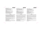
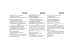
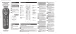
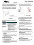
HP StorageWorks
Disk enclosure power
supply/blower replacement
instructions
About this document
This document describes the procedure for replacing the power
supply/blower assembly in MSA30, MSA1000, EVA3000/5000, and
EVA4x00/6x00/8x00 products.
NOTE:
Because this component is used in several products, the drawings
may reflect a different enclosure than the one you have. The
removal and replacement procedure is the same for each product.
Warranty information
These instructions apply to the MSA30, MSA1000,
EVA3000/5000, and EVA4x00/6x00/8x00
product families. The part may also be used in other
HP products. See the documentation for your product
for detailed replacement instructions.
If the product in which this part is being replaced is still under
HP warranty, then the replacement part(s) referred to in these
Replacement Instructions is provided under the terms and conditions
of the Hewlett-Packard Company Limited Warranty for that
product. A copy of this Limited Warranty may be viewed at:
http://h18006.www1.hp.com/products/storageworks/warranty.html
If this is a trade sale part (product out of warranty), then the replacement
part(s) referred to in these Replacement Instructions is provided under
HP's express limited warranty statement, which may be viewed at:
http://customerops.corp.hp.com/1sw/pdm_om/warranty_support/
policies/2330100.doc
The replacement part takes on either the Limited Warranty Period of the
part being replaced or a ninety-day period that begins upon installation
of the replacement part, whichever is greater.
The only warranty for this replacement product is as noted above.
Nothing in these replacement instructions should be construed as
constituting an additional warranty. The information provided in these
replacement instructions is provided "AS IS" and HP is not liable for
technical or editorial errors or omissions contained herein.
© Copyright 2005 Hewlett-Packard Development Company, L.P.
Fourth edition June 2007
The information in this document is subject to change without
notice.
Printed in Puerto Rico
www.hp.com
Before you begin
Observe the following precautions when replacing the power
supply/blower:
• You have only seven minutes to perform the replacement procedure!
Both power supplies must be installed for the enclosure to cool
properly. If a power supply fails, leave it in place in the enclosure
until a new power supply is available to install. The enclosure could
shut down due to overheating unless the power supply is replaced
within seven minutes of removal of the failed/failing power supply.
• If cabling is obstructing access to the power supply/blower, carefully
move the cables out of the way to avoid loosening any connections.
• Parts can be damaged by electrostatic discharge. Use proper
anti-static protection.
• Have a copy of the product user guide available for reference. You
can download a copy of the user guide from the product support
page on the HP website.
Verifying component failure
The power supply and blower are separately replaceable components.
Before replacing a power supply or blower, use the following methods
to verify component failure.
MSA products
*5697-6790*
• Check the power supply/blower status indicator (Figure 1). It should
be off.
Page 1
• On the front of the MSA1000, use the controller display buttons to
scroll through the messages displayed on the controller LCD panel
and locate the following message:
2
1
409 STORAGE BOX #<n> POWER SUPPLY FAILED
The <n> value in the message identifies which enclosure has the
failed power supply.
• Box 1: MSA enclosure
• Box 2: Disk enclosure attached to Port A of the MSA
• Box 3: Disk enclosure attached to Port B of the MSA
1
EVA products
0007a
Figure 2 Removing a blower
CAUTION:
If HP Command View EVA does not present a status consistent
with the power supply/blower status indicator, or if either HP
Command View EVA or your system monitoring tool indicates
multiple hardware failures, contact HP support for assistance
(http://www.hp.com/support).
Installing a blower
CAUTION:
• Analyze any failure messages received.
• Check status using HP Command View EVA:
1. In the Navigation pane, select Storage system > Hardware >
Rack > Disk enclosure.
2. In the Content pane, select the Power tab or the Cooling tab
then the appropriate component (1 or 2). The Operational state
Failed.
should be
3. To help identify the correct enclosure, click Locate > Locate On
to flash the status indicators on the front of the disk enclosure.
• Check the power supply/blower status indicator (Figure 1). It should
be off.
Pressing on the center section of the blower can damage the
blades or the housing. Only press on the outer edge of the blower
when installing it.
1.
Align the blower guide post (2, Figure 3) with the mounting hole
next to the power supply connector (1).
2. Slide the blower onto the power supply (4) until the mounting tabs
(3) snap into place.
4
3
1
2
3
1
2
3
0008a
Figure 3 Installing a blower
0006b
1. Status indicator
Removing a power supply
2. Power supply/blower 1
CAUTION:
3. Power supply/blower 2
When a power supply is removed, the enclosure could shut down
due to overheating within seven minutes unless the power supply
is replaced.
Figure 1 Power supply/blower status indicator
Removing a blower
1.
It is not necessary to remove the power supply to replace a failed
blower.
Disengage the power cord lock (1, Figure 4) and disconnect the
power cord from the power supply.
CAUTION:
WARNING!
When removing the left power supply, ensure the cord lock on
the right power supply is engaged. This will avoid inadvertently
disconnecting the right power supply. Also take care to avoid
disrupting the cables on the I/O module to left of the power
supply.
The blower motor does not stop immediately when the blower is
removed. Keep your fingers away from the blower blades until
the motor stops.
While pushing in on the two wine-colored mounting tabs (1, Figure 2),
pull the blower (2) away from the power supply.
Page 2
2. Lift up on the wine-colored mounting latch (2), then grasp the
blower (3) and pull the power supply out of the enclosure.
3. Remove the blower from the defective power supply and install it
on the replacement power supply.
Returning the failed component
Follow the return instructions provided with the new component.
2
1
3
0009a
Figure 4 Removing a power supply
Installing a power supply
1.
Lift up on the module latch (1, Figure 5) and slide the power supply
into the enclosure until it is fully seated.
2. Connect the power cord to the power supply and engage the
cord lock.
1
2
0010a
Figure 5 Installing a power supply
Verifying proper operation
After replacing the power supply or blower, check the following to verify
that the component is operating properly:
NOTE:
It may take up to 10 minutes for the component to display good
status.
• Ensure the blower begins operating immediately.
• Verify that he status indicator is on.
• On an MSA1000, the controller LCD panel should no longer
indicate a power supply/blower failure.
• From HP Command View EVA on an EVA product:
• Navigate to the component and check the status. It should be
.
• Turn off the locate function by clicking Locate > Locate Off.
Page 3