1
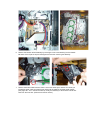
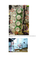
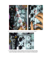
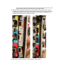
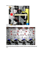
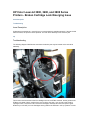
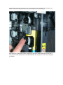
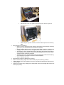
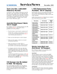
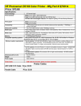
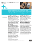
HP LaserJet 3000, 3600 and 3800 Series Printers Part Numbers Not Found in the Service Manual Introduction The following part numbers are not in the Service Manual. Part Numbers Part Description Part Number Duplex ETB RM1-2752-000CN Electronic transfer belt (ETB) simplex models RM1-2759-000CN Plate Lock Release/Tray 2 Lift Tab RC1-6833-020CN Relay PCB NOTE: This part for CLJ 3600 and 3800 models only. RM1-2632-000CN NOTE: This part for CLJ 3600 and 3800 models only. Tray 2 cassette pickup roller RM1-2702-000CN Toner cartridge lock kit Q5982-67925 NOTE: Please see Service Advisory c00775200 Tension spring (Figure 7-5, item 4 in Service Manual) RC1-6634-000CN Main drive assembly RM1-2751-000CN For HP and Channel Partner Internal Use SUPPORT COMMUNICATION - SERVICE ACTION ADVISORY Document ID: c00775200 Version: 5 HP Color LaserJet 3000, 3600 and 3800 Printers - Cartridge Lock Replacement Procedure Service Coverage Notice: Unless otherwise specified, HP is responsible for part and/or labor costs associated with products that are under HP warranty at the time of service. Release Date: 2006-12-11 Last Updated: 2006-12-11 DESCRIPTION The HP Color LaserJet 3800 Service Manual currently does not have instructions for replacing the main drive assembly or the cartridge locks. The cartridge locks are currently breaking and, until June 2006, the only solution was to replace the unit. NOTE: This Service Action Advisory supercedes Service Advisory c00673707. Please use this Service Action Advisory for repairs after 04-Dec-2006. A video of the replacement procedure is available: ftp://ftp.hp.com/pub/softlib/software8/COL17123/lj45472-1/tonerlock3.wmv SCOPE The products indicated in the table below are affected by this advisory. Product # Product Name Service Note Number for Reimbursement Product # Product Name Service Note Number for Reimbursement Q7533A HP Color LaserJet 3000 Q7533A - C00775200 Q7534A HP Color LaserJet 3000n Q7534A - C00775200 Q7535A HP Color LaserJet 3000dn Q7535A - C00775200 Q7536A HP Color LaserJet 3000dtn Q7536A - C00775200 Q5986A HP Color LaserJet 3600 Q5986A - C00775200 Q5987A HP Color LaserJet 3600n Q5987A - C00775200 Q5988A HP Color LaserJet 3600dn Q5988A - C00775200 Q5981A HP Color LaserJet 3800 Q5981A - C00775200 Q5982A HP Color LaserJet 3800n Q5982A - C00775200 Q5983A HP Color LaserJet 3800dn Q5983A - C00775200 Q5984A HP Color LaserJet 3800dtn Q5984A - C00775200 Products and Serial Number Cross Reference Product Number Starting Serial Number Ending Serial Number Q5981A CNABA00000 CNWBB72188 Q5982A CNABA00000 CNWBB54048 Q5982A CNABA00000 CNXBB30515 Q5983A CNACA00000 CNWCH30820 Q5983A JPACA00000 JPWCX01837 Q5983A JPACA00000 JPXCX00470 Q5984A CNACA00000 CNWCH31219 Q5984A JPACA00000 JPWCX01529 Q5987A CNABA00000 CNTBB53271 Q5988A CNACA00000 CNTCH31125 Q5988A JPACA00000 JPVCX00750 Q7534A CNABA00000 CNWBL05518 Q7534A CNABA00000 CNXBN03219 Q7535A JPACA00000 JPWCY00043 Q7535A JPACA00000 JPXCY00081 Q5981A CNAFA00000 CNXFB24233 Q5982A CNAFA00000 CNXFB24245 Q5983A CNAGA00000 CNXGH45539 Q5984A CNAGA00000 CNXGH45583 Q5986A CNAFA00000 CNVFB24244 Q5987A CNAFA00000 CNVFB24282 Q5988A CNAGA00000 CNVGH45972 Q7533A CNAFA00000 CNXFN04042 Product Number Starting Serial Number Ending Serial Number Q7534A CNAFA00000 CNXFN03331 Q7535A CNAGA00000 CNXGR00812 Q7536A CNAGA00000 CNXGS02350 Q5981A CNAA00000 CNWKF09263 Q5981A CNKAA00000 CNXKF03388 Q5982A CNKAA00000 CNXKB24756 Q5983A CNALA00000 CNWLH31062 Q5983A CNALA00000 CNXLH45244 Q5986A CNAKA00000 CNTKF01991 Q5986A CNAKA00000 CNVKB24542 Q5987A CNAKA00000 CNVKB24761 Q5988A CNALA00000 CNVLH46862 Q7534A CNAKA00000 CNXKL09425 Q7535A CNALA00000 CNXLS05851 RESOLUTION Steps have been created to help replace the cartridge locks, along with timing tips for the main drive assembly. The service kit contains four new locks and four new springs. Replace all the locks, even if they are not broken. NOTE: Determining if the printer has countermeasured or non-countermeasured cartridge locks can be accomplished by visually inspecting the locks. The countermeasured locks are white in color, the non-countermeasured locks are black. Parts Required Replacement Part Number Quantity Q5982-67922 1 Description Cartridge Lock Kit (to replace all 4 locks at one time) SERVICE ACTION To Be Performed By: Service Technicians 1. Remove the toner cartridges and ETB. 2. Remove the upper cover (Page 80 in the Service Manual). 3. Remove the right cover (Page 87 in the service Manual). 4. For duplex models: Remove the wires to the duplex fan in the front cover. Simply follow instructions 5 and 6 on page 77 ? 78 in the service manual. This allows for easier removal of the cable harnesses. 5. Unplug the following connectors from the driver PCA and remove the wires from the cable harnesses: a. J209, b. J406, c. J404, d. J213, e. J207, f. J203, g. J402, h. J206, I. J410, j. J208. 6. Remove the interlock switch assembly by removing the one screw attaching it to the chassis. Be aware of the clip at the top and the alignment knob when removing the assembly. 7. Remove the bottom cable harness. There is one screw at the top to remove. Hint: when you reinstall the guide, make sure that the rear locking tab is seated in the sheet-metal chassis. (See page 120 - 121 in the service manual). It may be necessary to disconnect the white door latch from the front door. (Notice the red arrow call-out). 8. Remove the main drive assembly (MDA). There are six screws attaching the MDA to the chassis. Carefully note the locations of the screws to be removed. CAUTION: Removing the incorrect screws could lead to opening up the MDA, requiring a unit replacement! NOTE: Two gears may fall off, there are instructions in step 16 on how to align them during the re-installation process. Remove the metal case by removing two screws. Remove the White Link Arm (see arrow in figure below) 9. Remove the white slide lever by pushing down from the top to release it from the two tabs. Carefully remove the lever by pulling out, be aware that four springs are attached to this lever and the individual cartridge locks. 10. Once the sliding lever is removed, the cartridge locks can be accessed. The new grounding springs are not on the new cartridge locks and will need to be attached. Look at the current springs on the machine for guidance, and at the instructions below. Make sure to feed the hooked end through the hole at the end of the lock to begin with (See figure below.). NOTE: The service kit has four new locks and four new springs in it, replace all the locks and springs, even if they are not currently broken. The new kit has white colored countermeasured locks. The picture below shows an old black non-countermeasured lock. 11. To attach the cartridge lock, hook the square part of the grounding spring to the metal chassis, then pull down and attach the lock on the metal shaft. NOTE: Replace all four cartridge locks, even though the others may not be broken. If one lock experienced failure, the others are more prone for failure later. 12. Attach one end the four springs to the white slide lever and install the lever back into the machine. (** Attach the other end of the spring in step 15.) Place the white slide lever so the two metal tabs are in place (circled below), then adjust all the black cartridge locks to be ?under? the tabs on the white slide lever. Bend the top of the white slide lever out to put the top black cartridge lock in place. Slide the white slide lever up when all the black cartridge locks are in place. 13. The slide lever and cartridge locks should look like the picture below when all is in place. 14. Lock the white slide lever in place by installing the metal case and white plastic piece. Make sure to insert the flange of the sheet metal in the slot on the sheet metal, and place the white shaft in the while slide lever. Reconnect the white arm to put tension on the white slide lever. 15. Connect the four springs on the white slide lever to each of the individual cartridge locks (start from the middle ones, it is easier that way). You will need needle-nosed pliers with pointed tips. The spring on the top is attached; the one on the bottom is not attached. Move the ETB guide to the up (vertical) position to help with removing and re-installing the Main Drive Assembly. 16. Make sure the gears are aligned properly before installing the main drive assembly. The four large gears should be in a approximate line (see picture). The top two large gears have an oval hole that aligns with a triangle stamped into the sheet metal. The two small gears to the right (they may fall off when removing the MDA), align with the three large bottom gears. Notice the two holes on each of the small gears align with the small holes of the large gears. NOTE: If this procedure has been properly followed, in the back of the printer, you will see the 4 white cams that control the movement of developers (see figure below). On the top and bottom shafts, you can see a black plastic part that has a flag associated with it. The top flag is for the black cartridge, the bottom flag is for all the color cartridges. Also, note that the white cams are all at different degrees of rotation. This reduces the force required to drive the motors when turning the cams. Metal shafts should be oriented with the empty space downwards. 17. Prepare the MDA for installation. Two areas must be checked: a. Make sure that all the white shafts are pushed to the right (clockwise) when the MDA is oriented as shown below (See the blue arrows in the image below.). The shafts are aligned correctly in the picture. NOTE: It is important that the ETB guides are in the up position to make installation of the MDA smooth. Hint: Rotate the shaft all the way to the right side first (as far as possible) then push them back a little to the left they will come to a hard stop. Leave them there. Look at the lines marks on the metal frame of the MDA (yellow arrows). b. Next, pay attention to the area marked with the two red arrows, enlarged in the picture below. It is possible that during the handling of the MDA one or both of these two gears can be mis-positioned by accident. If this happens, one or more of the color planes could be missed during printing. The gear on the right controls the black cartridge; it drives the larger gears to right below it to the right. The gear on the left controls all three of the color cartridges; it drives al the remaining three larger gears, the one directly below it and the two to the left. (Indicated by the dotted oval in the picture above). Check if they are properly aligned as follows: Both gears can be rotated either way to properly correct the MDA gears alignment. The images above show how to verify if the gears are correctly aligned. The two holes from larger gears should both be showing as illustrated by the red circles . (The large gears are under the frame and driven by the smaller gears.) 18. With the above in alignment, install the main drive assembly. Start at the left side, inserting the MDA into the metal slots and rotate it into position. Place a screw in the upper right corner of the MDA to help keep it in place if the MDA doesn?t fit flush when first installing it. This gives access with both hands to "jiggle" it into place. 19. Make sure the clips are pushed in and the MDA is seated properly. 20. At this point, reverse steps 7 on down. This will have the printer back up and running. Remember to correctly thread the cables through the wire harnesses properly! NOTE: The connector to the top cover is different between the simplex and duplex models. The duplex has a larger connector, while the Simplex is much smaller. If you experience the following issue after installing the new cartridge locks, here?s how to troubleshoot: AISS Main Drive Ass'y (MDA) rework possible side-effects Possible Failures After Rework 13.01.00/13.02.00 Close Top Cover/ Close Front Door Insert or Close Tray 2 • • • 10.92.XX Noise From Main Drive Assembly PQ-defect (i.e.: wrong color, Missing color pane, process CPR) Troubleshooting Check connection 1 (see #1 in Figure 1) • • Check connection 4 (see #4 in Figure 1) Check connection 3 (see #3 in Figure 1) Check connection 2 (see #2 in Figure 1) Check the cartridge bottom lock (see #5 in Figure 2) Remove the MDA and check all the Gears Alignment and correct as instructed. (for details, see steps 16 and 17 above and re-check the MDA alignment as shown in Figure 3 below) For noise specifically, check the Cartridge Drum Sensors on the MDA (see Figure 4) AISS Main Drive Ass'y (MDA) rework possible side-effects Possible Failures After Rework • Troubleshooting 54.XX Error 59.C0 Error One of the two drive gears on the engine is NOT correctly inserted. Remove MDA and re-align gears as instructed (see step 16 above) Figure 1: Troubleshooting connection checkpoints Figure 2: Troubleshooting lock position Figure 3: Troubleshooting gear alignment Noise - Check the Main Drive Assembly to see that the cartridge drum sensor is correctly seated. See the picture below for the proper orientation of the sensor. There are 4 of these (one per drum) on the MDA. Figure 4: Troubleshooting cartridge drum sensor Recommended Action: Fix on Specified Failure Objective: Recommended Modification LABOR ALLOWED Hours: 1 Minutes: 0 Service Delivery Type: Customer Site EFFECTIVE DATES Start: 2006-10-01 Expiration: 2008-10-01 WARRANTY COVERAGE Labor Covered: By Division Parts Covered: By Division Travel Covered: By Division Order Type Code (OTC): na PARTS LOGISTICS Parts Strategy: Standard Support Process Service Inventory: Scrap Used Parts: Scrap Used Parts: Scrap Hardware Platforms Affected: HP Color LaserJet 3000 Printer, HP Color LaserJet 3000n Printer, HP Color LaserJet 3000dn Printer, HP Color LaserJet 3000dtn Printer, HP Color LaserJet 3800 Printer, HP Color LaserJet 3800n Printer, HP Color LaserJet 3800dn Printer, HP Color LaserJet 3800dtn Printer, HP Color LaserJet 3600 Printer, HP Color LaserJet 3600n Printer, HP Color LaserJet 3600dn Printer Components Affected: na Operating Systems Affected: Not Applicable Software Affected: Not Applicable Third Party Products Affected: na Support Communication Cross Reference ID: IA00775200 REVISION HISTORY v.1.0 15-May-2006 original advisory v.2.0 21-Jun-2006 update to step 17 plus a few other minor edits v.3.0 18-Aug-2006 update multiple steps and add troubleshooting table v.4.0 18-Sep-2006 replaced SA c00673707 with this SAA (c00775200) to accommodate reimbursement after warranty period v.5.0 11-Dec-2006 added video link and serial number range Copyright 2006 Hewlett-Packard Development Company, L.P. Hewlett-Packard Company shall not be liable for technical or editorial errors or omissions contained herein. The information provided is provided "as is" without warranty of any kind. To the extent permitted by law, neither HP or its affiliates, subcontractors or suppliers will be liable for incidental, special or consequential damages including downtime cost; lost profits; damages relating to the procurement of substitute products or services; or damages for loss of data, or software restoration. The information in this document is subject to change without notice. Hewlett-Packard Company and the names of Hewlett-Packard products referenced herein are trademarks of Hewlett-Packard Company in the United States and other countries. Other product and company names mentioned herein may be trademarks of their respective owners. HP Color LaserJet 3000, 3600, and 3800 Series Printers - Broken Cartridge Lock Emerging Issue Issue Description Troubleshooting Issue Description Customers may experience a 10.92.XX error or cannot seat their cartridges properly. If the part circled below is broken, the printer must be replaced. The main drive assembly is not a service part. top Troubleshooting The following diagram identifies the area where the broken part may be located on the main drive assembly. This is how it should look then when the cartridges are out, the ETB is removed, but the guides to the ETB are up instead of down, and the front cover is all the way open: (you can get to this mode by opening the door, remove the ETB, remove the cartridges, close the front door, and open it again. Note that you can NOT put in the cartridges as the guides to the ETB are in the "up" position. Pull the guides down and the levers will go be in the correct position to insert cartridges. The white piece will be down and black locking levers will be up to allow easy insertion of the cartridge. Also check if the contact spring is being caught by the side frame sheet metal when the front door is being opened. There shouldn?t be an error associated with this, and you do not have to do anything if you see this. To help Division understand the issue better, when you have such a case, please gather this information: • • • • Model number and serial number Which Cartridge lock is broken (Black, Yellow, Cyan or Magenta?) Advise how the fault manifest's itself (Control Panel message, noises, can?t insert the cartridges, etc?) Describe the customer?s use of the discovery tape: o Did the customer pull on the tape or just follow it to the toner cartridges? o If the customer did pull on the tape, did the front door open quickly for them? Was the ETB attached to the front cover (see picture) when the door opened? • • • • • Was the ETB in the ?up? position (see picture) when the door opened? Please capture any other customer comments with respect to the discovery tape. When did this occur? (Select 1) o Right out of box? (the first time the customer removed the toner cartridge, could they get it out, or put it in?) Describe the customer?s comments. o Did the customer see an error on the control panel? Right out of box, or after printing XX pages? Document the number of pages, the error, and customer comments. o After inserting a toner cartridge after printing XX pages? (did customer feel anything odd compared to the insertion of the other toner cartridges?) Document the number of pages and the customers comments. o After removing a toner cartridge after printing XX pages?(did customer feel anything odd compared to the insertion of the other toner cartridges?) o Other??? (Please describe) Were there other signs of damage to the printer? Was the contact spring caught on the sheet metal (see picture above)? (Yes/No) Is there damage to the right hand side of the toner cartridge? Please describe/ take a picture of the damage. Check to see if there is any damage to the white plastic part for the cartridge that has the lock broken (see picture). • • top Is the printer sitting on a level surface? See the Service Action Advisory (Service Note) titled "HP Color LaserJet 3000, 3600 and 3800 Printers - Cartridge Lock Replacement Procedure", knowledgebase document number c00775200 .