1
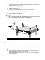
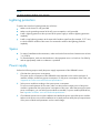
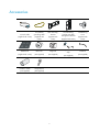
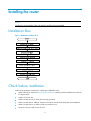
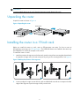
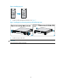
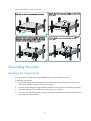
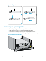
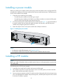
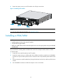
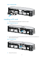
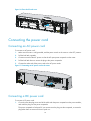
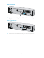
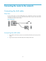
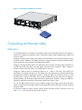
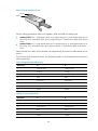
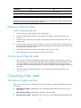
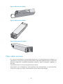
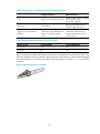
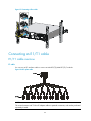
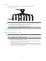
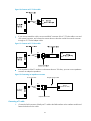
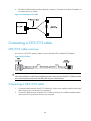
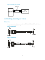
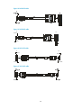
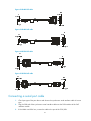
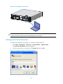
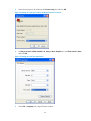
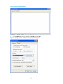
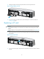
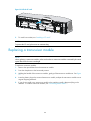
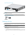
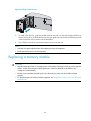
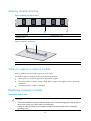
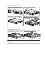
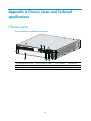
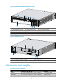
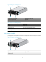
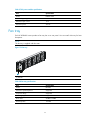
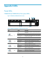
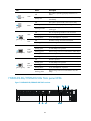
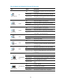
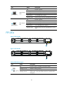
HP HSR6600 Routers
Installation Guide
5998-3100
Part number: 5998-3100
Document version: 6PW105-20140210
Legal and notice information
© Copyright 2014 Hewlett-Packard Development Company, L.P.
No part of this documentation may be reproduced or transmitted in any form or by any means without
prior written consent of Hewlett-Packard Development Company, L.P.
The information contained herein is subject to change without notice.
HEWLETT-PACKARD COMPANY MAKES NO WARRANTY OF ANY KIND WITH REGARD TO THIS
MATERIAL, INCLUDING, BUT NOT LIMITED TO, THE IMPLIED WARRANTIES OF MERCHANTABILITY
AND FITNESS FOR A PARTICULAR PURPOSE. Hewlett-Packard shall not be liable for errors contained
herein or for incidental or consequential damages in connection with the furnishing, performance, or
use of this material.
The only warranties for HP products and services are set forth in the express warranty statements
accompanying such products and services. Nothing herein should be construed as constituting an
additional warranty. HP shall not be liable for technical or editorial errors or omissions contained
herein.
Contents
Preparing for installation ············································································································································· 1 Safety recommendations ·················································································································································· 1 Safety symbols ·························································································································································· 1 General safety recommendations ··························································································································· 1 Electricity ··································································································································································· 2 Laser safety································································································································································ 2 Router moving ··························································································································································· 2 Examining the installation site ········································································································································· 2 Weight support ························································································································································· 2 Temperature and humidity ······································································································································· 3 Altitude ······································································································································································ 3 Cleanness ·································································································································································· 3 Cooling system ························································································································································· 4 ESD prevention ························································································································································· 4 EMI ············································································································································································· 5 Lightning protection ·················································································································································· 6 Space ········································································································································································· 6 Power supply····························································································································································· 6 Accessories ········································································································································································ 7 Installing the router ······················································································································································· 8 Installation flow ································································································································································· 8 Check before installation·················································································································································· 8 Unpacking the router ························································································································································ 9 Installing the router in a 19-inch rack ····························································································································· 9 Grounding the router ····················································································································································· 11 Installing the ring terminal ···································································································································· 11 Connecting the grounding cable ························································································································· 12 Installing a power module ············································································································································· 13 Installing a FIP module ··················································································································································· 13 Installing a HIM/MIM ···················································································································································· 14 Installing a CF card························································································································································ 15 Connecting the power cord ·········································································································································· 16 Connecting an AC power cord ··························································································································· 16 Connecting a DC power cord······························································································································ 16 Connecting the router to the network ······················································································································· 18 Connecting the AUX cable ············································································································································ 18 Overview ································································································································································ 18 Connecting the AUX cable ··································································································································· 18 Connecting an Ethernet cable······································································································································· 19 Overview ································································································································································ 19 Making an Ethernet cable ···································································································································· 21 Connecting an Ethernet cable ······························································································································ 21 Connecting a fiber cable ·············································································································································· 21 Transceiver module overview ······························································································································· 21 Fiber cable overview ············································································································································· 22 Connecting a fiber cable ······································································································································ 24 Connecting an E1/T1 cable ········································································································································· 25 E1/T1 cable overview ·········································································································································· 25 i
Connecting an E1/T1 cable ································································································································ 26 Connecting a CE3/CT3 cable ····································································································································· 28 CE3/CT3 cable overview ···································································································································· 28 Connecting a CE3/CT3 cable ····························································································································· 28 Connecting a serial port cable ····································································································································· 29 Overview ································································································································································ 29 Connecting a serial port cable ···························································································································· 31 Logging in to the router and configuring basic settings ·························································································· 33 Login methods································································································································································· 33 Logging in through the console port ···························································································································· 33 Preparation····························································································································································· 33 Setting up a configuration environment ·············································································································· 33 Setting terminal parameters·································································································································· 34 Verification before power-on ······························································································································· 37 Powering on the router ········································································································································· 37 Logging in to the router through Telnet/SSH ·············································································································· 38 Logging in to the router through the AUX port ············································································································ 38 Displaying the initial configuration ······························································································································ 39 Configuring basic settings ············································································································································· 39 Replacement procedures ··········································································································································· 41 Safety recommendations ··············································································································································· 41 Replacing a power module ··········································································································································· 41 Replacing a FIP module ················································································································································· 42 Replacing a HIM/MIM ·················································································································································· 42 Replacing a CF card ······················································································································································ 43 Replacing a transceiver module ··································································································································· 44 Replacing a fan tray ······················································································································································ 45 Replacing a memory module ········································································································································ 46 Memory module structure ····································································································································· 47 When to replace a memory module ··················································································································· 47 Replacing a memory module ······························································································································· 47 Hardware management and maintenance ·············································································································· 49 Displaying hardware information of the router··········································································································· 49 Displaying the software and hardware version information of the router······················································· 49 Displaying the operational statistics of the router ······························································································ 50 Displaying the detailed information about a module ························································································ 50 Displaying the electrical label information of a module ··················································································· 51 Displaying the CPU usage of a module ·············································································································· 52 Displaying the memory usage of a module ········································································································ 52 Displaying the CF card information ···················································································································· 53 Displaying the operational status of the built-in fan··························································································· 53 Displaying the operational status of power modules························································································· 54 Displaying the alarming thresholds of a module ········································································································ 54 Configuring a combo interface ···································································································································· 54 Combo interface overview ··································································································································· 54 Configuration prerequisites ·································································································································· 54 Configuring a combo interface ···························································································································· 56 Displaying transceiver module information and alarming information ···································································· 56 Introduction to transceiver modules ····················································································································· 56 Displaying transceiver module information ········································································································ 56 Displaying the alarming information or fault detection parameters for a transceiver module ······················ 57 Solving system faults ······················································································································································ 57 Solving system faults ············································································································································· 57 ii
Viewing the system fault solving method ············································································································ 58 Saving the current configuration of the router ············································································································ 58 Rebooting the router ······················································································································································ 58 Troubleshooting ·························································································································································· 60 Router failures ································································································································································· 60 Power status LEDs are off······································································································································ 60 RUN LED is off ······················································································································································· 60 RUN LED fast flashes ············································································································································· 60 ALM LED is steady on or flashes ·························································································································· 60 FIP module failure ··························································································································································· 61 Power module failures ··················································································································································· 61 Fan failures ····································································································································································· 62 Fan tray is absent ·················································································································································· 62 ALM LED is red ······················································································································································ 63 HIM/MIM failures ·························································································································································· 63 Configuration system problems ···································································································································· 63 No terminal display ·············································································································································· 63 Garbled terminal display······································································································································ 64 No response from the serial port ························································································································· 64 Dealing with password loss ·········································································································································· 64 Examining the state of password recovery capability ······················································································· 65 Dealing with console login password loss when password recovery capability is enabled ························ 66 Dealing with user privilege level password loss when password recovery capability is enabled ··············· 67 Dealing with password loss when password recovery capability is disabled ··············································· 68 Cooling system failure ··················································································································································· 69 Interface module, cable, and connection failure ········································································································ 70 Software upgrade failures ············································································································································· 70 No response from the serial port ························································································································· 70 TFTP upgrade failure ············································································································································· 70 FTP upgrade failure ··············································································································································· 71 Application file missing errors ······································································································································ 71 Appendix A Chassis views and Technical specifications ······················································································· 73 Chassis views ································································································································································· 73 Dimensions and weights ················································································································································ 74 Storage media ································································································································································ 75 Power consumption ························································································································································ 75 Power module ································································································································································· 75 AC power module ················································································································································· 75 DC power module ················································································································································· 76 Fan tray ··········································································································································································· 77 Port specifications ·························································································································································· 78 Ports and slots ························································································································································ 78 Console port ·························································································································································· 78 AUX port ································································································································································· 78 Management Ethernet port ··································································································································· 79 Combo interface ···················································································································································· 79 10 Gbps Ethernet port ·········································································································································· 80 Flexible interface platform modules ····························································································································· 81 FIP-10 ······································································································································································ 81 FIP-20 ······································································································································································ 82 Interface modules ··························································································································································· 83 Appendix B LEDs ························································································································································ 84 Panel LEDs ······································································································································································· 84 iii
HSR6602-G/HSR6602-G TAA panel LEDs········································································································ 84 HSR6602-XG/HSR6602-XG TAA panel LEDs ··································································································· 85 FIP LEDs ··········································································································································································· 87 HIM/MIM LEDs ······························································································································································ 88 Power module LEDs ························································································································································ 88 Appendix C Cable management ······························································································································ 89 General cabling requirements ······································································································································ 89 Minimum curvature radius of cables ··················································································································· 89 Minimum curvature radius of fibers ····················································································································· 89 Labeling cables······························································································································································· 89 Cable management guidelines ····································································································································· 90 Cable routing example ·················································································································································· 92 Appendix D Arranging slots and numbering interfaces ·························································································· 94 Slot arrangement ···························································································································································· 94 Slot arrangement for FIPs ·············································································································································· 94 Numbering interfaces ···················································································································································· 95 Examples ········································································································································································· 95 Example 1 ······························································································································································ 95 Example 2 ······························································································································································ 95 Support and other resources ····································································································································· 97 Contacting HP ································································································································································ 97 Subscription service ·············································································································································· 97 Related information ························································································································································ 97 Documents ······························································································································································ 97 Websites································································································································································· 97 Conventions ···································································································································································· 98 Index ········································································································································································ 100 iv
Preparing for installation
The HP HSR6600 Router Series is a line of high-performance centralized product, which includes the
models in Table 1.
Table 1 Models for the HP HSR6600 Routers
Product code
Full name
RMN
Abbreviation
JG353A
HP HSR6602-G Router
BJNGA-BB0001
HSR6602-G
JG354A
HP HSR6602-XG Router
BJNGA-BB0001
HSR6602-XG
JG776A
HP HSR6602-G TAA Router
BJNGA-BB0001
HSR6602-G TAA
JG777A
HP HSR6602-XG TAA Router
BJNGA-BB0001
HSR6602-XG TAA
JG357A
RT-FIP-10
FIP-10
FIP-10
JG358A
RT-FIP-20
FIP-20
FIP-20
IMPORTANT:
For regulatory identification purposes, every HSR6600 Router is assigned a regulatory model
number(RMN). These regulatory numbers should not be confused with the marketing name HP HSR6600,
or product codes.
Safety recommendations
Safety symbols
When reading this document, note the following symbols:
WARNING means an alert that calls attention to important information that if not understood or
followed can result in personal injury.
CAUTION means an alert that calls attention to important information that if not understood or
followed can result in data loss, data corruption, or damage to hardware or software.
General safety recommendations
•
Make sure that the ground is dry and flat and anti-slip measures are in place.
•
Keep the chassis and installation tools away from walk areas.
•
Make sure the installation site is well grounded, and lightning protection and ESD-prevention are
provided.
•
Only trained and qualified personnel are allowed to install or service the router.
•
Keep accessories, installation tools, and documentation safe.
•
Avoid bodily injury. Do not touch any power plug when it is connected.
•
Clean up the packaging materials after installation to avoid fire hazard.
1
Electricity
•
Locate the emergency power-off switch in the room before installation. Shut the power off at once in
case accident occurs.
•
Make sure that the router has been correctly grounded.
•
Use an uninterrupted power supply (UPS).
•
If there are two power inputs, disconnect the two power inputs to power off the router.
•
Do not work alone when the router has power.
•
Always check that the power has been disconnected.
Laser safety
The HP HSR6600 routers are Class 1 laser devices.
WARNING!
• Do not stare into any fiber port when the router has power. The laser light emitted from the optical fiber
may hurt your eyes.
• Use a fiber test equipment, rather than a microscope or magnifier to observe an operating fiber or port
when you test link connectivity or system parameters.
Router moving
When you move an HSR6600 router, follow these guidelines:
•
Move and unpack the router carefully to avoid router damage.
•
Use a safety hand truck when you move a heavy device or multiple devices.
•
Before you move the router, remove all the cables, USB devices, mounting brackets, and cable
management brackets.
•
If the router needs to be moved over a long distance, remove all the field-replaceable units (FRUs),
such as power modules, fan trays, and interface modules, and package them separately, and install
the filler panels supplied with router.
•
If the router needs to be moved over a short distance, make sure all the FRUs are securely seated in
slot and the screws are fastened.
•
When you move or lift the router chassis, support the bottom of the chassis, rather than holding any
FRU. Make sure the accessories of the router are not lost or damaged during router moving.
Examining the installation site
Weight support
Evaluate the floor loading as compared to the actual weight of the router and its accessories (such as
rack and power modules), and make sure that the floor can support the weight of the rack and the router
chassis. For more information, see “Appendix A Chassis views and Technical specifications.”
2
Temperature and humidity
Maintain appropriate temperature and humidity in the equipment room.
•
Lasting high relative humidity can cause poor insulation, electricity creepage, mechanical property
change of materials, and metal corrosion.
•
Lasting low relative humidity can cause washer contraction and ESD and bring problems including
loose captive screws and circuit failure.
•
High temperature can accelerate the aging of insulation materials and significantly lower the
reliability and lifespan of the router.
For the temperature and humidity requirements of the router, see Table 2.
Table 2 Temperature requirements
Item
Temperature
Operating temperature
0°C to 45°C (32°F to 113°F)
Storage temperature
–40°C to 70°C (–40°F to +158°F)
Table 3 Humidity requirements
Item
Relative humidity
Operating humidity
5% to 95%
Storage humidity
5% to 95%
Altitude
Table 4 Altitude requirements
Item
Altitude
Operating altitude
–60 m (–196.85 ft) to 4 km (2.49 miles)
Storage altitude
–60 m (–196.85 ft) to 4.5 km(2.8 miles)
Cleanness
Dust buildup on the chassis may result in electrostatic adsorption, which causes poor contact of metal
components and contact points, especially when indoor relative humidity is low. In the worst case,
electrostatic adsorption can cause communication failure.
Table 5 Dust concentration limit in the equipment room
Substance
Dust particles
Concentration limit (particles/cu m)
≤ 3 x 10⁴
(No visible dust on desk in three days)
NOTE:
Dust particle diameter ≥ 5 μm
3
The equipment room must also meet strict limits on salts, acids, and sulfides to eliminate corrosion and
premature aging of components, as shown in Table 6.
Table 6 Harmful gas limits in an equipment room
Gas
Max. (mg/m3)
SO2
0.2
H2S
0.006
NH3
0.05
Cl2
0.01
Cooling system
The HSR6600 routers adopt left to right airflow for heat dissipation.
Figure 1 Airflow
•
Make sure there is enough space (greater than 10 cm (3.94 in)) around the air intake and outlet
vents on the router for good ventilation.
•
Make sure the installation site has a good cooling system.
ESD prevention
To prevent electrostatic discharge (ESD), note the following guidelines:
•
Make sure that the router and rack are well grounded.
•
An anti-static floor is installed and well grounded.
•
Maintain the humidity and temperature at a proper level in the equipment room. For more
information, see “Temperature and humidity.”
•
Always wear an ESD-preventive wrist strap and ESD-preventive cloth when touching a circuit board,
interface module, or transceiver module.
•
Place the removed memory module, CF card, FIP, HIM, or MIM on an antistatic workbench, with the
face upward, or put it into an antistatic bag.
4
Touch only the edges, instead of electronic components when observing or moving a removed
memory module, CF card, HIM, or MIM.
•
To use the ESD-preventive wrist strap, perform the following steps:
1.
Wear the wrist strap on your wrist.
2.
Lock the wrist strap tight around your wrist to keep good contact with the skin.
3.
Attach the ESD-preventive wrist strap to the alligator clips.
4.
Attach the alligator clips to the rack post.
5.
Make sure that the rack is well grounded.
CAUTION:
• Check the resistance of the ESD-preventive wrist strap for safety. The resistance reading should be in the
range of 1 to 10 megohm (Mohm) between human body and the ground.
• The HSR6600 does not provide any ESD-preventive wrist strap. Prepare it yourself.
Figure 2 Use an ESD-preventive wrist strap
1
2
3
(1) ESD-preventive wrist strap
(2) Lock
(3) Alligator clip
EMI
All electromagnetic interference (EMI) sources, from outside or inside of the router and application system,
adversely affect the router in a conduction pattern of capacitance coupling, inductance coupling,
electromagnetic wave radiation, or common impedance (including grounding system) coupling. To
prevent EMI, perform the following tasks:
•
Take measures against interference from the power grid.
•
Do not use the router together with the grounding equipment or light-prevention equipment of
power equipment, and keep the router far away from them.
•
Keep the router far away from high-power radio launchers, radars, and equipment with high
frequency or high current.
5
NOTE:
Use electromagnetic shielding when necessary.
Lightning protection
To protect the router from lightning better, do as follows:
•
Make sure the chassis is well grounded.
•
Make sure the grounding terminal of the AC power receptacle is well grounded.
•
Install a lightning protector at the input end of the power supply to enhance lightning protection
capability.
•
Install a surge lightning protector at the input end of outdoor signal lines (for example, E1/T1 line)
to which interface modules of the router are connected to enhance the lightning protection
capability.
Space
•
For ease of installation and maintenance, make sure that the front and rear clearances are at least
1 m (3.28 ft).
•
For heat dissipation, make sure the headroom in the equipment room is no less than 3 m (9.84 ft),
and an appropriately sized air conditioner is provided.
Power supply
Perform the following steps to satisfy the power supply requirements of the HSR6600 routers:
1.
Calculate the system power consumption.
The system power consumption of the HSR6600 routers depends on the number and type of
interface modules, and fan tray power consumption. For the power consumption of the router, see
“Appendix A Chassis views and Technical specifications.”
2.
Select power modules according to the system power consumption.
To ensure normal operation of the router, make sure the maximum output power of the power
modules is greater than the system power consumption of the router. After determining the system
power consumption, you can select power modules as needed. For power module specifications,
see “Appendix A Chassis views and Technical specifications.”
3.
Check that the power source on the installation site satisfies the power input of the power modules.
Make sure the power source of the installation site is steady and can satisfy the input requirements
of the power modules and parameters such as rated voltage.
6
Accessories
3 m (9.84 ft)
grounding cable
Rear mounting
bracket
(supplied with
router)
(supplied with
router)
Rubber feet
M6 screw
Cage nuts
(supplied with router)
(user-supplied)
(user-supplied)
Console cable
(supplied with router)
Front mounting
bracket and cable
management bracket
(supplied with router)
Load-bearing
screw
(supplied with
router)
Insulation sheath
Ring terminal
(user-supplied)
(user-supplied)
7
ESD-preventive wrist
strap
(user-supplied)
Cable tie
(user-supplied)
Installing the router
NOTE:
The fan tray, power modules, FIPs, and interface modules are hot swappable.
Installation flow
Figure 3 HSR6600 installation flow
Check before installation
Follow these guidelines to prepare for installing an HSR6600 router:
•
Make sure that you have read “Preparing for installation” carefully and the installation site meets all
the requirements.
•
Prepare a 19-inch rack.
•
Make sure that the rack is sturdy and securely grounded.
•
Make sure that there is sufficient clearance around the rack for heat dissipation and installation.
•
Make sure that there is no debris inside or around the rack.
•
Move the router to a place near the rack.
8
IMPORTANT:
To mount multiple devices in the rack, place the heaviest one at the bottom of the rack.
Unpacking the router
Unpack the router as shown in Figure 4.
Figure 4 Unpacking the router
Foam brace
Packing belt
Installing the router in a 19-inch rack
Before you install the router to a rack, wear an ESD-preventive wrist strap. For how to wear an
ESD-preventive wrist strap, see “ESD prevention.” The HSR6600 Routers are installed in the same way.
The HSR6602-G is used as an example in this section.
To install the router in a rack:
1.
Mark the positions of cage nuts on the front rack posts by using a front mounting bracket and mark
the positions of cage nuts on the rear rack posts by using a rear mounting bracket. See Figure 5.
Figure 5 Marking the positions of the cage nuts
2.
Insert one edge of a cage nut into the hole, and use a flat-blade screwdriver to compress the other
edge of the cage nut to push the cage nut fully into the hole.
9
Figure 6 Installing cage nuts
3.
Install the cable management brackets. See Figure 7.
Figure 7 Installing the front mounting brackets and load-bearing screws
4.
Install the router to the rack.
CAUTION:
This task requires at least two people.
10
Figure 8 Installing the router to the rack
Grounding the router
Installing the ring terminal
No ring terminal is supplied with the grounding cable. You must install one yourself.
To install the ring terminal:
1.
Cut the grounding cable as appropriate for connecting to the grounding strip, and strip 5 mm
(0.20 in) of insulation sheath by using a wire stripper.
2.
Insert the bare metal part through the black insulation covering into the end of the ring terminal.
3.
Crimp the metal part of the cable to the ring terminal with a crimper.
4.
Cover the joint with the insulation covering, and heat the insulation covering with a blow dryer to
completely cover the metal part.
11
Figure 9 Installing the ring terminal
Ring terminal
Grounding cable
Insulation sheath
5mm
1
2
3
4
Connecting the grounding cable
1.
Remove the grounding screw from the rear panel of the router chassis.
2.
Attach the grounding screw to the ring terminal of the grounding cable.
3.
Use a screwdriver to fasten the grounding screw into the grounding screw hole.
4.
Attach the ring terminal on the other end of the grounding cable to the grounding strip.
Figure 10 Connecting the ground


![[halshs-00226409, v1] Le capitalisme cognitif](http://vs1.manualzilla.com/store/data/006431954_1-d5f5b99f626575718765e6de43f4c03f-150x150.png)