1
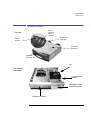
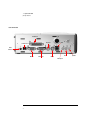
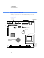
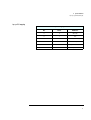
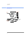
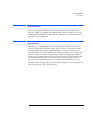
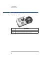
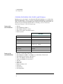
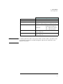
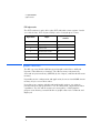
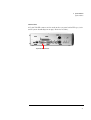
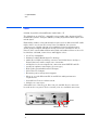
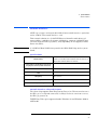
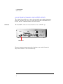
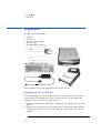
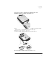
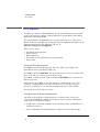
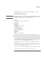
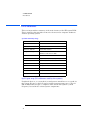
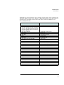
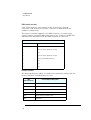
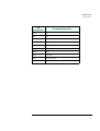
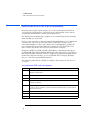
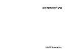
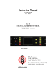
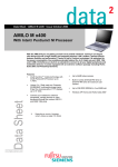
technical reference manual
product description - hp e-pc
This technical reference and BIOS document for the HP e-pc contains
summary information only. More detailed information on system hardware is
available in the Technical Reference Manual - HP PC Technology.
HP e-pc
Contents
1 system overview
hp e-pc components and technical features. . . . . . . . . . . . . . . . . . . . . 2
package features . . . . . . . . . . . . . . . . . . . . . . . . . . . . . . . . . . . . . . . . . . . 3
specifications . . . . . . . . . . . . . . . . . . . . . . . . . . . . . . . . . . . . . . . . . . . . . . 5
2 system features
hp e-pc system board layout . . . . . . . . . . . . . . . . . . . . . . . . . . . . . . . . 10
architectural view . . . . . . . . . . . . . . . . . . . . . . . . . . . . . . . . . . . . . . . . . 12
main memory . . . . . . . . . . . . . . . . . . . . . . . . . . . . . . . . . . . . . . . . . . . . . 13
processors . . . . . . . . . . . . . . . . . . . . . . . . . . . . . . . . . . . . . . . . . . . . . . . 13
CMOS/password switch . . . . . . . . . . . . . . . . . . . . . . . . . . . . . . . . . . . . 14
mass storage devices. . . . . . . . . . . . . . . . . . . . . . . . . . . . . . . . . . . . . . . 15
graphic interface . . . . . . . . . . . . . . . . . . . . . . . . . . . . . . . . . . . . . . . . . . 18
audio . . . . . . . . . . . . . . . . . . . . . . . . . . . . . . . . . . . . . . . . . . . . . . . . . . . . 22
network interface . . . . . . . . . . . . . . . . . . . . . . . . . . . . . . . . . . . . . . . . . 23
3 serviceability
swapping parts . . . . . . . . . . . . . . . . . . . . . . . . . . . . . . . . . . . . . . . . . . . . 26
Francais iii
4 BIOS overview
BIOS summary . . . . . . . . . . . . . . . . . . . . . . . . . . . . . . . . . . . . . . . . . . .
30
power saving and ergonometry . . . . . . . . . . . . . . . . . . . . . . . . . . . . .
33
BIOS addresses. . . . . . . . . . . . . . . . . . . . . . . . . . . . . . . . . . . . . . . . . . .
34
order in which the POST tests are performed . . . . . . . . . . . . . . . . .
38
beep codes and error messages . . . . . . . . . . . . . . . . . . . . . . . . . . . . .
44
5 drivers and software
drivers . . . . . . . . . . . . . . . . . . . . . . . . . . . . . . . . . . . . . . . . . . . . . . . . . .
46
software . . . . . . . . . . . . . . . . . . . . . . . . . . . . . . . . . . . . . . . . . . . . . . . . .
46
BIOS updates . . . . . . . . . . . . . . . . . . . . . . . . . . . . . . . . . . . . . . . . . . . .
47
iv Francais
1
system overview
This chapter introduces the internal and external features, and lists the
specifications of the HP e-pc.
1 system overview
hp e-pc components and technical features
hp e-pc components and technical features
Component
Package
Description
Processor
HP e-pc
No Free access shelves
Width: 8.9cm (3.5 in); Height: 24.0 cm (9.4 in); Depth: 27.2 cm (10.7 in).
Intel Celeron 500/66, 533/66, 633/66, 700/66
Intel Pentium III 600EB/133, 667/133, 800/133, 866/133
System Board:
Chip set
Intel® 810E
Integrated I/O
On ICH chip. 2 USB connectors, 1 serial port and 1 parallel port, 2 PS/2 (keyboard, mouse), 1 15-pin VGA connector, audio ports (stereo-in,
stereo-out, microphone in)
Integrated IDE
On ICH chip. 2 IDE Ports (Ultra ATA 66)
Integrated
Graphics
Intel® 810E integrated graphics with Direct AGP and Dynamic Video Memory Technology.
Integrated Audio
CS4299: CrystalClear™ Sound Fusion Audio Codec ‘97
Integrated network
interface
3COM 10/100 Mbps 3C905C-TX Network Interface (RJ-45 Ethernet port (10/100Base-T)
Mass storage
Main memory
Input devices
Power supply
BIOS
Hard disks: 8.4GB IDE, 10GB IDE, 20GB IDE
CD-ROM drive: 24X Max-speed slim CD-ROM (in selected models)
DVD drive: 8x Max-speed (in selected models)
CD-RW drive: Available as accessory C4505A
USB Floppy drive: Available as accessory D9510A
One SDRAM socket using: 64MB, 128MB, 256MB
HP Standard Keyboard
HP Scrolling Mouse
External 60W Power Supply
Type: AmiBIOS
Version: IN.xx.yy
Setup program: English only
BIOS error messages: English only
2
1 system overview
package features
package features
Power on
Status Light
(flashes in
sleep mode)
Front view
Hard Disk Drive
Activity Light
Power On/
Off Button
Hard Disk Drive
compartment
CD-ROM Drive
(some models only)
Fan
Front view with
cover removed
Processor located
below fan
Main Memory located
behind RFI filler plate.
CD-ROM, DVD or CD-RW drive
3
1 system overview
package features
rear connectors
Parallel Port
USB
Keyboard
LAN Connector
Power
Connector
Monitor
Serial Ports
Line In
Mouse
Microphone
4
Speaker
1 system overview
specifications
specifications
physical characteristics
Characteristic
Description
Weight
(excluding display and keyboard)
3.5 kg (7.7 pounds)
Dimensions
Width: 8.9cm (3.5 inches)
Height: 24.0cm (9.4 inches)
Depth: 27.2 cm (10.7 inches)
Footprint
Vertical Position1: 0.021 m2 (0.23 ft.2)
Horizontal Position: 0.065 m2 (0.69 ft.2)
Power Adapter
Input voltage: 100-240 Vac (auto-range)
Input frequency: 50/60 Hz
Output Voltage: 19V
Maximum output power: 60W (max)
Power Consumption (components)
Nominal: 30W
Windows 98 Suspend: 15W
1.
Dimensions do not include the stand
5
1 system overview
specifications
both platforms
power consumption
As an ENERGY STAR partner, HP has determined that this product meets the
ENERGY STAR guidelines for energy efficiency (standard base models).
Power Consumption
(PC running Windows98)
Operating with input/output:
38W
Operating without input/output:
21W
Suspend:
15W
Automatic Sleep Mode:
4.1W
Off:
2.2W
These are “typical” values given for the standard base models.
NOTE
When the PC is turned off with the power button on the front panel, the power
consumption falls below 5 Watts, but is not zero. The special on/off method
used by this PC extends the lifetime of the power supply. To reach zero power
consumption in “off” mode, unplug the AC adapter from the power outlet or
unplug the AC adapter from the HP e-pc. If the PC is turned off, the time
settings are maintained by the battery indefinitely (until the battery runs out
of power).
acoustic noise emission
Acoustic Noise Emission
(ISO 7779)
Sound Power
(Average)
Sound Power
(ISO 9296)
Sound Pressure
(ISO 9296)
Operating (idle)
LwA =32.4 dBA
LwAd = 33 dBA
LpA = 24 dBA
Operating with disk access
LwA = 39.1 dBA
LwAd = 42 dBA
LpA = 34 dBA
Operating with CD-ROM access
LwA = 44.7 dBA
LwAd = 48 dBA
LpA = 37 dBA
The values are given for the standard configuration as shipped and can vary
depending on the actual components used.
6
1 system overview
specifications
environmental specifications
Environmental Specifications (System Processing Unit, with Hard Disk)
Operating Temperature
5oC - 35oC
Storage Temperature
-40oC to 70oC
Operating Humidity
15% to 80% (relative)
Storage Humidity
8% to 85% (relative), non-condensing at 40°C (104°F)
Acoustic Noise Emission:
(as defined ISO 7779)
Sound level (LwA) ≤ 37 db (operating)
Operating Altitude
10000 ft (3100m) max
Storage Altitude
15000ft (4600m) max
Operating temperature and humidity ranges may vary depending upon the
mass storage devices installed. High humidity levels can cause improper
operation of disk drives. Low humidity levels can aggravate static electricity
problems and cause excessive wear of the disk surface.
7
1 system overview
specifications
8
2
system features
This chapter describes core components of the HP e-pc such as processors,
chip set, mass storage devices, graphics controller, audio controller, network
features and input devices.
2 system features
hp e-pc system board layout
hp e-pc system board layout
All HP e-pc system boards have a Celeron/Pentium III processor slot.
system board
2 stacked USB
connectors
Line
OUT
Line
Mic IN
IN
Power Connector
Keyboard
mouse
LAN
LAN
The parallel port is located
above Serial Port and VGA
connector
IDE connector
Audio
HDD Power Connector
CMOS/Password
Switch
CD-ROM connector
Battery Socket
Processor Socket
810E chipset with
embedded graphics
Status panel
connector
Memory
slot
Power Fan
connector
10
2 system features
hp e-pc system board layout
hp e-pc PCI mapping
HP e-pc PCI Mapping Table
Bus
Device
PCI Device
0
0
MCH chip
0
1
VGA
0
30
ICH chip: PCI bridge
0
31
ICH chip
0
31
Integrated audio (CoDec)
1
2
Integrated LAN
11
2 system features
architectural view
architectural view
Processor
Celeron or Pentium III
Display
System Memory
System Bus
(66/133MHz)
GMCH
Intel
82810e
64bit
(66/100MHz)
266 MB/s
LAN
PCI 33
HDD and CDD
ICH
Intel
82801AA
CS4299
LPC Bus
AUDIO AC97
USB
FWH
INTEL 82802AB(4M)
12
ATA33/66
Super
I/O
PS/2 KB and MS
Serial and //
2 system features
main memory
main memory
There is one 168-pin DIMM slot on the system board for installing main
memory. All HP e-pc models are supplied with a memory module of at least
64 MB non-ECC SDRAM. Only HP memory modules are supported. Memory
upgrades are not supported.
processors
The HP e-pc is equipped with either a single Socket 370 Intel Celeron or
socket 370 Intel Pentium III processor. Socket 370 is a conversion of Slot 1
(used previously by Celerons and Pentium Is) to a socket, running at the
same bus protocol as the Pentium II (the GTL+ bus protocol). The processor
is connected to the system board through a Plastic Pin Grid Array (PPGA)
370 Socket. The reduction in size achieved by the Socket 370 Celeron is due
to the integration of the L2 cache on the processor die. Like the Celeron
processor, the Pentium III comes in a 370-pin socket (PGA370) package.
To find out more about Socket 370 Celeron technology, refer to the Technical
Reference Manual - HP PC Technology.
13
2 system features
CMOS/password switch
CMOS/password switch
The position of the CMOS/password switch is shown below:
SWITCH BLOCK
Switch
CMOS/
Password
14
Switch function:
OFF = normal (default)
ON = clear CMOS and reload default values in Setup, clear Passwords
2 system features
mass storage devices
mass storage devices
hard disk drives
A 3.5-inch hard disk drive is supplied. This hard drive is provided with the
HP e-pc and comes with a hard disk drive tray attached. To see which other
hard disk drives can be purchased as accessories for the HP e-pc, refer to
www.hp.com/go/pcaccessories.
8.4GB
Ultra-ATA 66
10 GB
Ultra-ATA 100
20 GB
Ultra-ATA 100
Average Seek Times (ms)
12
8.9
<9
I/O data-transfer rate
(Mbytes/Sec max)
66
66
66
ATA data-transfer modes supported
PIO modes 0-4
Multiword DMA modes 0-2
Ultra DMA modes 3-4
Internal Data Rate (Mb/s)
248
330
330
Buffer Size Ultra ATA
512 KM
2 MB
2 MB
To find out about Ultra-ATA DMA 33/66 hard disk drive technology, refer to
the Technical Reference Manual - HP PC Technology.
15
2 system features
mass storage devices
CD-ROM (CD/CD-ROM, CD-R, CD-RW) and DVD drives
Models may be fitted with a 24✕ Max Slim IDE CD-ROM drive or 8 x Max Slim
IDE DVD-ROM drive. These can play standard CD-ROM discs, conforming to
optical and mechanical standards as specified in the Red and Yellow Book. To
find out about CD-ROM and DVD drive technology, refer to Technical
Reference Manual - HP PC Technology.
features of the
slim CD-ROM drive
•
•
•
•
•
CD-DA
CD-ROM Mode1,Mode 2
CD-I (Mode 2 Form 1 and 2)
Photo-CD (single and multisession)
Enhanced CD
Description
HP product number
Host Interface
IDE (ATAPI)
Disc Diameter
120 mm
Storage Capacity
656 Mbytes
Data Transfer Rate
Burst: 33.3 MBs (max)
Sustained: 1545 ~3600KBs
Features of the
slim DVD-ROM Drive
Average Access Time
115msec (average)
Buffer Memory
128 Kbytes
Rotational speed
5136rpm
•
•
•
•
•
•
•
•
•
•
•
•
CD-DA as defined by Red Book
CD-ROM data in Mode 1 and Mode 2 as defined by Yellow book
CD-ROM XA data Form 1 and Form 2
CD-I, CD-I Bridge and CD-I Ready
Single and Multiple Session discs
CD-RW
Video CD
Photo CD
Enhanced Music CD
DVD Disc
DVD-R Disc
DVD-RAM Disc
16
2 system features
mass storage devices
Description
HP product number
Disc Diameter
Disk Capacity
Data Transfer Rate
Random Access Time
Full Stroke
1.Constant
NOTE
120 mm
CD-ROM: 656MB (mode 1), 748MB (mode 2)
DVD-ROM: 4.7 GBytes (Single Layer), 8.5 GBytes (Dual Layer)
Sustained
CD-ROM: Max 3.6 MBytes/sec
DVD-ROM: Max 5.4 MBytes/sec
24 MAX CAV1
1550 ~3600 Kbytes/sec (Mode1)
1768 ~4106 Kbytes (Mode2)
170 ms (typical)
270 ms (average max.)
320 ms (typical)
480 ms (average max.)
Angular velocity
If a disk is still in the drive after power failure or drive failure, the disk can be
reclaimed by inserting a straightened paper-clip into the small hole at the
bottom of the door.
17
2 system features
graphic interface
DVD region codes
The DVD software is only able to play DVD video discs from regions 1 and 2
(see table below). DVD region settings can be changed up to 5 times.
Region Codes
Region
Supported by the DVD
software
1
USA & Canada
Yes
2
Europe & Japan
Yes
3
South East Asia
No
4
Latin America & Australia
No
5
Russia, Rest of Asia, Africa
No
6
China
No
graphic interface
The HP e-pc uses Intel® 810E integrated graphics with Direct AGP and
Dynamic Video Memory technology. The video memory is dynamically
allocated on system memory (SDRAM) by the chip set, and shared with main
memory.
Depending on the configuration and application, between 4 and 10MB of main
memory may be reserved for video.
Its architecture consists of dedicated multi-media engines executing in
parallel to deliver high performance 3D, 2D and motion compensation video
capabilities. The 3D and 2D engines are managed by a 3D/2D pipeline
preprocessor allowing a sustained flow of graphics data to be rendered and
displayed.
18
2 system features
graphic interface
specifications
•
Integrated Graphics Controller
❒ 3D Hyper Pipelined Architecture
❒ Full 2D H/W Acceleration
❒ Motion Video Acceleration
•
3D Graphics Visual Enhancements
❒ Flat & Gouraud Shading
❒ Mip Maps with Bilinear and Anisotropic Filtering
❒ Fogging Atmospheric Effects
❒ Z Buffering
❒ 3D Pipe 2D Clipping
❒ Backface Culling
•
3D Graphics Texturing Enhancements
❒ Per Pixel Perspective Correction Texture Mapping
❒ Texture Compositing
❒ Texture Color Keying/Chroma Keying
•
Display
❒ Integrated 24-bit 230 MHz RAMDAC
❒ Gamma Corrected Video
❒ DDC2B Compliant
19
2 system features
graphic interface
2D Graphics
•
❒ Up to 1600x1200 in 8-bit Color at 75 Hz Refresh
❒ Hardware Accelerated Functions
❒ 3 Operand Raster BitBLTs
❒ 64x64x3 Color Transparent Cursor
Arithmetic Stretch Blitter Video
•
❒ H/W Motion Compensation Assistance for S/W MPEG2 Decode
❒ Software DVD at 30 fps
❒ H/W Overlay Engine with Bilinear Filtering
❒ Independent gamma correction, saturation, brightness & contrast for
overlay
Integrated Graphics Memory Controller
•
❒ Intel®. D.V.M. Technology
supported resolutions
The following non-interlaced resolutions are supported for Windows 2000 and
WIndows 98, with ergonomic refresh rates up to 1280 x 1024:
20
Resolution
256 colors
(8-bit)
64K colors
(16-bit)
16.7M colors
(24-bit)
640 × 480
800 × 600
1024 × 768
60–85Hz
60–85Hz
60–85Hz
60–85Hz
60–85Hz
60–85Hz
60–85Hz
60–85Hz
60–85Hz
1152 × 864 1
1280 × 1024
1600 × 1200
60–85Hz
60–85Hz
60–75Hz
60–85Hz
60–85Hz
60–85Hz
60–85Hz
2 system features
graphic interface
connectors
A 15-pin VGA DB connector is located on the rear panel of the HP e-pc (refer
to the system board diagram on page 10 for its location).
15-pin VGA DB Connector
21
2 system features
audio
audio
CS4299: CrystalClear Sound Fusion Audio Codec ‘97
The CS4299 is an AC’97 2.1 compatible stereo audio codec designed for PC
multimedia systems. Using the industry leading CrystalClear delta-sigma and
mixed signal.
High fidelity audio is achieved through features such as differential CD audio
input, which cancels out PC activity noise. In addition, the system’s
converters are a highly efficient over-sampling scheme to perform up to
20-bit analog-to-digital and digital-analog conversion. Through its use of
DirectX, this crystal audio solution offers high-end audio features such as 3-D
localization, surround, room effects and Doppler effect:
• AC ‘97 2.1 Compatible
• Industry Leading Mixed Signal Technology
• 20-bit Stereo Digital-to-Analog converter and 18-bit Stereo Analog to
Digital Converter with a sample rate conversion.
• Analog line-level stereo inputs for connection from LINE IN and CD
• Analog microphone mono input (electret type)
• High quality pseudo-differential CD input
• Stereo line-level output
• Extensive power management support
• Meets or exceeds Microsoft PC 98 and PC 99 audio performance
requirements
• CrystalClear 3D stereo enhancement
• Sample rate converters
All models have a Line In jack, Line Out jack and Mic In jack connector
located on the rear panel. These external jacks are standard connectors.
speaker
Microphone
22
Line In
2 system features
network interface
network interface
All HP e-pcs feature an integrated 10/100 3Com network interface equivalent
to the 3C905C-TX network interface card.
This network solution is a 32-bit PCI Ethernet Controller with advanced
manageability capabilities. It features full-duplex, automatic 10/100 BT port
selection, Remote Wake-Up (RWU), and, depending on OS support, Remote
Power-On (RPO).
NOTE
A 3COM LAN Boot ROM is integrated in the BIOS ROM chip on the system
board.
specifications
Network Interface
I/O Base Address: The NIC address can be selected
using diagnostic software provided with the driver
Transmit/Receive Buffer Memory
Labels
Manageability
Power Management
Pre-OS boot protocol support
Ethernet IEEE 802.3 industry standard 10 Mbps baseband CSMA/CD
(10BASE-T) and 100 Mbps baseband CSMA/CD (100Tx, FX) standards, 10
Mbps baseband CSMA/CD (10BASE2 and 10BASE5).
Any 32-bit I/O base address NIC occupies 32 bytes of I/O space
4 KB. 2 KB transmit, 2 KB receive
Microsoft PC97, Microsoft PC98, Microsoft PC99, Net PC, PCI 2.2
DMI 2.0 and 2.0s
ACPI 1.0
PXE, BootP/DHCP, NCP, RPL
network interface advanced features
The 3Com chip supports First Plug Remote Power On. This means that once
the HP e-pc is set up and connected, if a Magic Packet is sent from a server,
the HP e-pc powers on.
TCP/IP Ping Wake-up is supported under Windows 98 and Windows 2000 in
ACPI mode.
23
2 system features
network interface
network interface diagnostics (not installed by default)
The 3Com Network Interface driver also includes an in-depth diagnostics
program. It enables the user to test the LAN chip, the network Interface
layers, and the communication between machines.
connectors
The 10/100BT connector is located on the rear of the HP e-pc.
LAN Connector
For more information on network technology, refer to the Technical
Reference Manual - HP PC Technology.
24
3
serviceability
This chapter introduces the enhanced serviceability features of the
HP e-pc.
3 serviceability
swapping parts
swapping parts
The HP e-pc has 5 modules:
•
•
•
•
•
mouse
keyboard
external power supply
HP e-pc unit
hard disk drive and tray
These modules have been designed for easy replacement.
returning your HP e-pc for repair
The hard disk drive has been designed to be easily removed. In the event of
system failure, HP Support may advise you to remove your hard disk and
return the system for repair or replacement
1 Switch off the monitor and HP e-pc. Unplug the AC adapter from the wall
socket.
2 Using the key, unlock the port control system (if installed) and hard drive
compartment cover at the rear of the HP e-pc. Remove the port control
system.
26
3 serviceability
swapping parts
3 Disconnect the power cord and any telecommunication cables.
4 Slide back and then lift off the compartment cover.
5 Lift the rear of the hard drive tray clear of the HP e-pc using the handle.
This is to gain access to the data and power connectors.
6 Remove the data and power connectors.
7 Using the handle, lift the hard drive tray out of the HP e-pc.
The hard disk drive should never be removed from it’s tray.
27
3 serviceability
swapping parts
28
4
BIOS overview
This chapter describes the BIOS features of HP e-pc models.
4 BIOS overview
BIOS summary
BIOS summary
The HP e-pc contain an HP/AMI BIOS. The system ROM contains the POST
(power-on self-test) routines, and the BIOS: the System BIOS, video BIOS,
and 3Com LAN option ROM.
The system BIOS is identified by the version number IN.xx.yy. The latest
BIOS version for your HP e-pc and instructions for updating the BIOS can be
downloaded from the HP’s Support Web site at:
www.hp.com/go/e-pcsupport
This section covers:
•
•
•
•
•
The BIOS Setup program
Power saving
BIOS addresses
The order in which POST tests are performed
Beep codes
using the HP setup program
Press F2 to run the Setup program, when the “HP” logo is displayed
immediately after restarting the HP e-pc.
Press F8 to enter the Boot menu. Use the boot menu to select the order of the
devices the HP e-pc will use to start (boot) from.
Press F12 to boot on LAN. This overrides the Boot Policy selected from the
HP Setup Screen.
Alternatively, press Esc to view the summary configuration screen. The
summary configuration screen will remain on the screen until a key is
pressed. A summary screen will also be displayed at the end of POST.
The Setup screen has only one menu.
auto-detection and auto-configuration
Auto-detection and auto-configuration are essential to the ease of use
concept. The HP BIOS avoids users having to enter Setup by automating
many of the selection procedures:
• Conflict detection and resolution of system board, PCI, and PnP devices
and their resources.
• Auto-configuration and optimization of chip set based on bus speeds
30
4 BIOS overview
BIOS summary
• IDE HDD auto-detection, including support for IDE drives > 8.4GB
• ATAPI CD-ROM auto-detection
• PS/2 Mouse and Keyboard detection
NOTE
A USB floppy is installed as a standard drive by the BIOS (drive A: or E:). A
USB floppy is installed as drive A: (for Windows 2000) or drive E: (Windows
98), depending on the number of external drives attached.
HP setup screen
The Setup page contains the following fields:
•
•
•
•
•
•
•
•
•
•
•
•
•
System Time
System Date
Boot Policy
F12 Hot Key to Boot on LAN
CD-ROM
Set Supervisor Password
Set User Password
Integrated Audio Interface
Integrated USB Interface
Serial Port
Parallel Port
Mode
Processor Serial Number1
The menu items contained in this page are largely security features. The
purpose of this page is to facilitate the prevention of Unauthorized users from
using or booting from selected drives and network connections for example:
• Boot Policy: Allows you to select the devices and the order of the devices
from which the BIOS attempts to boot the operating system. During POST,
if the BIOS is unsuccessful at booting from one device, it will then try the
next one on the list until an operating system is found.
• F12 Hot Key to Boot On LAN: Allows the user to enable or disable this
feature.
• CD-ROM, Integrated Audio Interface, Integrated USB Interface, Serial
Port and Parallel Port: These menu items enable you to unlock/lock these
integrated Data Communications Ports
• Supervisor Password. This password prevents unauthorized access to the
1.
This menu item is hidden when the Celeron processor is detected.
31
4 BIOS overview
BIOS summary
computer’s configuration. It can also be used to start the computer.
• User Password. This password can only be set when a supervisor password
has been set. The User Password prevents unauthorized use of the
computer, protects stored data.
32
4 BIOS overview
power saving and ergonometry
power saving and ergonometry
soft power down
Soft Power Down is available with the Windows NT operating system. If users
want to shut down their HP e-pc, they are able to do so directly from the
Windows NT interface. There is no longer any need to physically switch off
the HP e-pc.
The hardware to do this is contained in the ICH chipset. This chipset is
described in detail in Technical Reference Manual - HP PC Technology.
safe off
Safe Off is available with Windows NT4.0 operating systems. If users attempt
to shut down the operating system when an application is open and has not
been saved, they are requested to save their work before the computer can be
powered off.
NOTE
Safe Off is integrated in Windows 98 and Windows 2000.
The hardware to do this is contained in the ICH chipset. This chipset is
described in detail in Technical Reference Manual - HP PC Technology.
33
4 BIOS overview
BIOS addresses
BIOS addresses
This section provides a summary of the main features of the HP system BIOS.
This is software that provides an interface between the computer hardware
and the operating system.
system memory map
0000 0000 - 0000 03FF
Real-mode IDT
0000 0400 - 0000 04FF
BIOS Data Area
0000 0500 - 0009 FC00
Used by OS
0009 FC00 - 0009 FFFF
Extended BIOS Data Area
000A_0000 - 000B_FFFF
Video RAM or
SMRAM (not visible unless in SMM)
000C 0000 - 000C 7FFF
Video ROM
000C 8000 - 000F FFFF
Adapter ROM, RAM, memory-mapped registers
000E 0000 - 000F FFFF
System BIOS (Flash/Shadow)
10 0000 - FF FFFF
Memory (1 MB to 16 MB)
100 0000 - 1FF FFFF
Memory (16 MB to 32 MB)
200 0000 -3FF FFFF
Memory (32 MB to 64 MB)
400 0000 -1FFF FFFF
Memory (64 MB to 512 MB)
FFF80000 - FFFF FFFF
512 KB BIOS (Flash)
hp I/O port map (I/O addresses used by the system)
Peripheral devices, accessory devices and system controllers are accessed via
the system I/O space, which is not located in system memory space. The 64
KB of addressable I/O space comprises 8-bit and 16-bit registers (called
I/O ports) located in the various system components.
34
4 BIOS overview
BIOS addresses
Although the Setup program can be used to change some of the settings, the
following address map is not completely BIOS dependent, but is determined
partly by the operating system. Note that some of the I/O addresses are
allocated dynamically.
I/O Address Ports
0000 - 000F
0010-001F, 0022 -003F, 0044-005F,
0062-0063, 0065-006F, 0072-007F, 0084-0086,
04D0-04D1, 0080, 0088, 008C-008E, 0090-009F,
00A2-00BF, 00E0-00EF, 0400-047F, 0480-04BF,
04D0-04D1, 0800-0847F
0020 - 0021, 00A0-00A1
0040 - 0043
0060, 0064
0061
0070 - 0071
0081 - 0083, 008F, 0087, 0089-008B,
00C0-00DF
00F0 - 00FF
0170 - 0177
01F0 - 01F7
0376
0378 - 037F, 0778 - 077F
03F8 - 03FF
0CF8 - 0CFF
03B0-03BB, 03C0-03DF
0540-054F
B000-BFFF
BC00-BC7F
03F6, FFA0 - FFA7, FFA0-FFAF
D400-D41F
D800-D83F, DCFF
FFA0-FFA7
FFA0-FFAF
FFA8-FFAF
Function
DMA controller
Motherboard resources
Programmable Interupt Controller
System Timer
PC/AT Enhanced Keyboard
System Speaker
RTC and CMOS data
DMA Controller
Numeric Data Processor
Ultra ATA Controller, Secondary ATA Controller
Ultra ATA Controller, Primary ATA Controller
Ultra ATA Controller, Secondary ATA Controller
LPT1 ECP
COM1
PCI bus
Chipset Graphic Drivers
SMBus controller
PCI Bridge
NIC
Ultra ATA Controller, Primary ATA Controller
USB Universal Host Controller
Audio
Primary ATA Controller
Ultra ATA Controller
Secondary ATA Controller
35
4 BIOS overview
BIOS addresses
DMA channel controllers
Only “I/O-to-memory” and “memory-to-I/O” transfers are allowed.
“I/O-to-I/O” and “memory-to-memory” transfers are disallowed by the
hardware configuration.
The system controller supports seven DMA channels, each with a page
register used to extend the addressing range of the channel to 16 MB. The
following table summarizes how the DMA channels are allocated.
DMA controller
Channel
Function
0
Free
1
Free if not used for parallel port in Setup
2
Free
3
Free if not used for parallel port in Setup
4
Used to cascade DMA channels 0-3
5
Free
6
Free
7
Free
interrupt controllers
The Interrupt Requests (IRQ) are numbered sequentially, starting with the
master controller, and followed by the slave.
IRQ
(Interrupt Vector)
Interrupt Request Description
INTR
IRQ0
System Timer
IRQ1
Keyboard Controller
IRQ3
3 COM LAN
IRQ4
Used by serial post if enabled - CON1
IRQ5
Audio AC’97
36
4 BIOS overview
BIOS addresses
IRQ
(Interrupt Vector)
Interrupt Request Description
IRQ6
Free
IRQ7
LPT1
IRQ8
RTC
IRQ9
On board USB Controller
IRQ10
VGA
IRQ11
SCI ACPI
IRQ12
Mouse
IRQ13
Co-processor
IRQ14
IDE Primary channel
IRQ15
IDE Secondary channel. Free unless disabled
37
4 BIOS overview
order in which the POST tests are performed
order in which the POST tests are performed
Each time the system is powered on, or a reset is performed, the POST is
executed. The POST process verifies the basic functionality of the system
components and initializes certain system parameters.
The POST starts by displaying a graphic screen of the Hewlett-Packard logo
when the HP e-pc is started.
Devices, such as memory and newly installed hard disk drives, are configured
automatically. The user is not requested to confirm the change. Newly
removed hard disks are detected, and the user is prompted to confirm the
new configuration by pressing F4. Note, though, that the POST does not
detect when a hard disk drive has been otherwise changed.
During the POST, the BIOS and other ROM data is copied into high-speed
shadow RAM. The shadow RAM is addressed at the same physical location as
the original ROM in a manner which is completely transparent to applications.
It therefore appears to behave as very fast ROM. This technique provides
faster access to the system BIOS firmware.
The following table lists the POST checkpoint codes written at the start of
each test.
uncompressed INIT code checkpoints
01
NMI is Disabled. CPU ID saved.Init code Checksum verification starting.
02
To do DMA init, Keyboard controller BAT test, start memory refresh
and going to 4GB flat mode.
D3
To start Memory sizing.
D4
To comeback to real mode. Execute OEM patch. Set stack.
D5
E000 ROM enabled. Init code is copied to segment 0 and control to be
transfered to segment 0.
D6
Control is in segment 0. To check <CTRL><HOME> key and verify main BIOS checksum.
If either <CTRL><HOME> is pressed or main BIOS checksum is bad, go to check point E0
else goto check point D7.
D7
To pass control to Interface Module.
08
Main BIOS runtime code is to be decompressed.
09
Control to be passed to main BIOS in shadow RAM.
38
4 BIOS overview
order in which the POST tests are performed
boot block recovery code check points
E0
OnBoard Floppy Controller (if any) is initialzed. To start base 512K memory test.
E1
To initialise interrupt vector table.
E2
To initialise DMA and interrupt controllers.
E6
To enable floppy and timer IRQ, enable internal cache.
ED
Initialize floppy drive.
EE
Start looking for a diskette in drive A: and read 1st sector of the diskette.
EF
Floppy read error.
F0
Start searching 'AMIBOOT.ROM' file in root directory.
F1
'AMIBOOT.ROM' file not present in root directory.
F2
Start reading FAT table and analyze FAT to find the clusters occupied by 'AMIBOOT.ROM' file..
F3
Start reading 'AMIBOOT.ROM' file cluster by cluster.
F4
'AMIBOOT.ROM' file not of proper size.
F5
Disable internal cache.
FB
Detect Flash type present.
FC
Erase Flash.
FD
Program Flash.
FF
Flash program successful. BIOS is going to restart.
runtime code is uncompressed in F000 shadow ram
03
NMI is Disabled. To check soft reset/power-on.
05
BIOS stack set. Going to disable Cache if any.
06
POST code to be uncompressed.
07
CPU init and CPU data area init to be done.
08
CMOS checksum calculation to be done next.
0B
Any initialization before keyboard BAT to be done next.
0C
KB controller I/B free. To issue the BAT command to keyboard controller.
0E
Any initialization after KB controller BAT to be done next.
0F
Keyboard command byte to be written.
10
Going to issue Pin-23,24 blocking/unblocking command.
39
4 BIOS overview
order in which the POST tests are performed
11
Going to check pressing of <INS> , <END> key during power-on.
12
To init CMOS if "Init CMOS in every boot" is set or <END> key is pressed. Going to disable DMA
and Interrupt controllers.
13
Video display is disabled and port-B is initialized. Chipset init about to begin.
14
8254 timer test about to start.
19
About to start memory refresh test.
1A
Memory Refresh line is toggling. Going to check 15us ON/OFF time.
23
To read 8042 input port and disable Megakey GreenPC feature. Make BIOS code segment
writeable.
24
To do any setup before Int vector init.
25
Interrupt vector initialization about to begin. To clear password if necessary.
27
Any initialization before setting video mode to be done.
28
Going for monochrome mode and color mode setting.
2A
Different BUSes init (system, static, output devices) to start if present. (Please see Appendix for
details of different BUSes).
2B
To give control for any setup required before optional video ROM check.
2C
To look for optional video ROM and give control.
2D
To give control to do any processing after video ROM returns control.
2E
If EGA/VGA not found then do display memory R/W test.
2F
EGA/VGA not found. Display memory R/W test about to begin.
30
Display memory R/W test passed. About to look for the retrace checking.
31
Display memory R/W test or retrace checking failed. To do alternate Display memory R/W test.
32
Alternate Display memory R/W test passed. To look for the alternate display retrace checking.
34
Video display checking over. Display mode to be set next.
37
Display mode set. Going to display the power on message.
38
Different BUSes init (input, IPL, general devices) to start if present. (Please see Appendix for details
of different BUSes).
39
Display different BUSes initialization error messages. (Please see Appendix for details of different
BUSes).
3A
New cursor position read and saved. To display the Hit <DEL> message.
40
To prepare the descriptor tables.
42
To enter in virtual mode for memory test.
40
4 BIOS overview
order in which the POST tests are performed
43
To enable interrupts for diagnostics mode.
44
To initialize data to check memory wrap around at 0:0.
45
Data initialized. Going to check for memory wrap around at 0:0 and finding the total system
memory size.
46
Memory wrap around test done. Memory size calculation over. About to go for writing patterns to
test memory.
47
Pattern to be tested written in extended memory. Going to write patterns in base 640k memory.
48
Patterns written in base memory. Going to findout amount of memory below 1M memory.
49
Amount of memory below 1M found and verified. Going to findout amount of memory above 1M
memory.
4B
Amount of memory above 1M found and verified. Check for soft reset and going to clear memory
below 1M for soft reset. (If power on, go to check point# 4Eh).
4C
Memory below 1M cleared.(SOFT RESET) Going to clear memory above 1M.
4D
Memory above 1M cleared.(SOFT RESET) Going to save the memory size. (Goto check point# 52h).
4E
Memory test started.(NOT SOFT RESET) About to display the first 64k memory size.
4F
Memory size display started. This will be updated during memory test. Going for sequential and
random memory test.
50
Memory testing/initialization below 1M complete. Going to adjust displayed memory size for
relocation/ shadow.
51
Memory size display adjusted due to relocation/ shadow. Memory test above 1M to follow.
52
Memory testing/initialization above 1M complete. Going to save memory size information.
53
Memory size information is saved. CPU registers are saved. Going to enter in real mode.
54
Shutdown successful, CPU in real mode. Going to disable gate A20 line and disable parity/NMI.
57
A20 address line, parity/NMI disable successful. Going to adjust memory size depending on
relocation/shadow.
58
Memory size adjusted for relocation/shadow. Going to clear Hit <DEL> message. Going to clear
Hit <DEL> message.
59
Hit <DEL> message cleared. <WAIT...> message displayed. About to start DMA and
interrupt controller test.
60
DMA page register test passed. To do DMA#1 base register test.
62
DMA#1 base register test passed. To do DMA#2 base register test.
65
DMA#2 base register test passed. To program DMA unit 1 and 2.
66
DMA unit 1 and 2 programming over. To initialize 8259 interrupt controller.
7F
Extended NMI sources enabling is in progress.
41
4 BIOS overview
order in which the POST tests are performed
80
Keyboard test started. clearing output buffer, checking for stuck key, to issue keyboard reset
command.
81
Keyboard reset error/stuck key found. To issue keyboard controller interface test command.
82
Keyboard controller interface test over. To write command byte and init circular buffer.
83
Command byte written, Global data init done. To check for lock-key.
84
Lock-key checking over. To check for memory size mismatch with CMOS.
85
Memory size check done. To display soft error and check for password or bypass setup.
86
Password checked. About to do programming before setup.
87
Programming before setup complete. To uncompress SETUP code and execute CMOS setup.
88
Returned from CMOS setup program and screen is cleared. About to do programming after setup.
89
Programming after setup complete. Going to display power on screen message.
8B
First screen message displayed. <WAIT...> message displayed. PS/2 Mouse check and extended
BIOS data area allocation to be done.
8C
Setup options programming after CMOS setup about to start.
8D
Going for hard disk controller reset.
8F
Hard disk controller reset done. Floppy setup to be done next.
91
Floppy setup complete. Hard disk setup to be done next.
95
Init of different BUSes optional ROMs from C800 to start. (Please see Appendix-I for details of
different BUSes).
96
Going to do any init before C800 optional ROM control.
97
Any init before C800 optional ROM control is over. Optional ROM check and control will be done
next.
98
Optional ROM control is done. About to give control to do any required processing after optional
ROM returns control and enable external cache.
99
Any initialization required after optional ROM test over. Going to setup timer data area and printer
base address.
9A
Return after setting timer and printer base address. Going to set the RS-232 base address.
9B
Returned after RS-232 base address. Going to do any initialization before Coprocessor test.
9C
Required initialization before Coprocessor is over. Going to initialize the Coprocessor next.
9D
Coprocesor initialized. Going to do any initialization after Coprocessor test.
9E
Initialization after Coprocessor test is complete. Going to check extd keyboard, keyboard ID and
num-lock. Keyboard ID command to be
A2
Going to display any soft errors.
42
4 BIOS overview
order in which the POST tests are performed
A3
Soft error display complete. Going to set keyboard typematic rate.
A4
Keyboard typematic rate set. To program memory wait states.
A5
Going to enable parity/NMI.
A7
NMI and parity enabled. Going to do any initialization required before giving control to optional ROM
at E000.
A8
Initialization before E000 ROM control over. E000 ROM to get control next.
A9
Returned from E000 ROM control. Going to do any initialization requiredafter E000 optional ROM
control.
AA
Initialization after E000 optional ROM control is over. Going to display the system configuration.
AB
To build MP table if needed.
AC
To uncompress DMI data and execute DMI POST init.
B0
System configuration is displayed.
B1
Going to copy any code to specific area.
00
Copying of code to specific area done. Going to give control to INT-19 boot loader.
43
4 BIOS overview
beep codes and error messages
beep codes and error messages
If a terminal error occurs during POST, the system issues a beep code before
attempting to display the error in the upper left corner of the screen. Beep
codes are useful for identifying the error when the system is unable to display
the error message.
Number of
Beeps
44
Error Message
Description
1
Refresh Failure
The memory refresh circuitry on the motherboard is faulty.
2
Parity Error
Parity error in the first 64 KB of memory.
3
Base 64KB Memory Failure
Memory failure in first 64 KB.
4
Timer Not Operational
Memory failure in the first 64 KB of memory, or Timer 1 on
the M/B is not functioning.
5
Processor error
The CPU(Central Processing unit) on the M/B generated an
error.
6
Processor Exception
Interrupt Error
The CPU generated an exception interrupt.
7
Processor Exception
Interrupt Error
The CPU generated an exception interrupt.
8
Display Memory Read/ Write
Error
The system video adapter is either missing or its memory is
faulty. This is not a fatal error.
9
ROM Checksum Error
The ROM checksum value does not match the value
encoded in the BIOS.
10
CMOS Shutdown Register
Read/ Write Error
The shutdown register for CMOS RAM failed
11
Cache Error/ External Cache
Bad
The external cache is faulty
5
drivers and software
This chapter provides information on the drivers and software preloaded
with the HP e-pc.
5 drivers and software
drivers
drivers
You can download up-to-date versions of drivers required for the HP e-pc
from the “Software and Drivers” section of HP’s Support web site at
www.hp.com/go/e-pcsupport.
software
HP e-pc models come preloaded with the following software. You can
download the most up-to-date versions from the “Software and Drivers”
section of HP’s Support web site at www.hp.com/go/e-pcsupport.
operating systems• Windows 98 SE or Windows 2000 (note that you can install Windows NT 4.0
instead of Windows 2000 on some models)
software• e-DiagTools
• Norton AntiVirus 2000 (s10 small business models only)
• Online documentation
• SoftOff
• TopTools
• UDF Reader
• Adobe Acrobat
• Microsoft Word 2000 (some models)
• Microsoft Office 2000 SB (some models)
• Microsoft Works 2000 (some models)
• Information Center (only on s10 small business models and in some
countries)
• e-pc c10 help (c10 corporate models only)
46
5 drivers and software
BIOS updates
BIOS updates
The system BIOS is identified by the version number IN.xx.yy. The latest
BIOS version for your PC and instructions for updating the BIOS can be
downloaded from the HP support Web site at:
www.hp.com/go/e-pcsupport.
47
5 drivers and software
BIOS updates
48
about this document
This technical reference and BIOS document for the HP e-pc contains
summary information only. More detailed information on system hardware is
available in the Technical Reference Manual - HP PC Technology.
hp e-pc bibliography
❒ HP Information CD-ROM (see HP e-pc User’s Guide for ordering
information)
❒ Technical Reference Manual -HP PC Technology
www.hp.com/go/e-pcsupport
❒ HP e-pc Service Handbook Chapter at:
www.hp.com/go/e-pcsupport.
❒ HP Support Assistant CD-ROM (by subscription).
Data sheets can be obtained at:
❒ Pentium Processors
www.intel.com/design/pentiumIII/datashts
❒ Product Data Sheet
www.hp.com/e-pc
xlix
l
The Technical Reference Manual contains the following
documents available on the HP Information CD-ROM or
downloadable from the Web in PDF format:
•
Introduction & HP e-pc Overview
Describes how to use the Technical Reference Manual and provides
a brief overview of the HP e-pc.
•
Product Description
The document you are reading. Provides detailed BIOS information
and summary information on the hardware components in the HP
e-pc.
•
HP PC Technology
A detailed look at the hardware components in the HP e-pc and
selected HP Vectra PCs. Includes information on processors, chip
set, graphics controller, network interface, connectors and sockets.