1
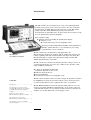
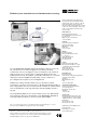
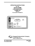
HP 37722A telecom analyzer
HP 37732A telecom/datacom
analyzer
Technical specifications
Introduction
The HP 37722A telecom analyzer is an easy-to-use, lightweight fieldportable test set for in-service and out-of-service bit error and signal
measurement on CEPT digital circuits and services. The HP 37722A
analyzer provides framed/unframed pattern generation and
measurements at and 2 Mb/s. Also, it offers many other features to help
increase productivity and network uptime:
●
n × 64 kb/s testing
● timeslot monitor including all signaling bits display
● timeslot access
● event-based storage in text and graphic form.
Options provide framed/unframed 8 Mb/s, framed/unframed
704 kb/s, 64 kb/s timeslot access and sub-rate processing
(X.50 divisions 2 and 3, and X.58).
HP 37722/32A
telecom/datacom analyzer
The HP 37722A telecom analyzer is easily upgraded to the
HP 37732A telecom/datacom analyzer, which combines the full telecom
testing capability of the HP 37722A analyzer with datacom testing. The
HP 37732A analyzer consists of the HP 37722A analyzer and the HP
15901A Option 001 datacom module.
The HP 37732A telecom/datacom analyzer provides testing at V.24, V.35,
V.11/X.21-leased interfaces at rates up to 2 Mb/s. It also provides a full
range of BER measurements:
●
●
●
●
Contents
Introduction ............................................ 2
Specifications for telecom testing
using the HP 37722A telecom analyzer
or the HP 37732A telecom/datacom
analyzer ................................................... 3
control-circuit timing analysis with
transitions diagrams on the screen
built-in V.24 breakout box
internal synthesizer
event-based storage in text and graphic form.
The HP 37732A analyzer reduces test time and speeds problem resolution
by simplifying test setup. It presents results in easy-to-read and easy-torecord ways that make it easy to pinpoint the cause of a problem.
The HP E4540A distributed network analyzer (DNA) software, for a PC
or laptop operating with Microsoft Windows®, can be used to remotely
control the HP 37722A telecom analyzer or HP 37732A telecom/datacom
analyzer over modem links from a local support center.
Datacom testing using the
HP 37732A telecom/datacom analyzer .... 4
Specifications common to the
HP 37722A and 37732A analyzers .......... 5
Specifications of options available
for both analyzers .................................... 6
2
Specifications for telecom testing using the
HP 37722A telecom analyzer or the
HP 37732A telecom/datacom analyzer
Telecom specifications
Transmitter
Receiver
Bit rates: 2.048 Mb/s, 64 kb/s;
optional 8.448 Mb/s, 704 kb/s, sub64 kb/s.
Frame structure: 2 Mb/s
unframed, to ITU-T G.704, G.706,
G.732, G.704: with no multiframe;
with CAS multi-frame with/
without CRC4 multiframe;
64 kb/s codirectional; independent
setting for transmitter and
receiver.
Interfaces: To ITU-T G.703 and
G.823.
Timing: Recovered (loop timed),
internal, external.
Internal clock: 2.048 MHz,
64 kHz, (± 10 ppm).
2 Mb/s receiver
Connectors
BNC: 75 ohm, unbalanced.
3-pin Siemens: 120 ohm,
balanced.
Modes of operation
Transmit, receive, through mode.
Auto setup
Bit rate, line code, framing and
pattern.
Test patterns
PRBS: 211 − 1 (ITU-T O.153),
215 − 1, 223 − 1 (ITU-T O.151)
(inverted or non-inverted).
Word: Fully programmable n-bit
word (n=8 to 1024); all ones, 1 in 2
(1010).
Timeslot selection: All
timeslots, single timeslot, n
timeslots for n = 1 to 31
(contiguous or non-contiguous).
Receive timeslot as for
transmitter, or independently set.
Deselected timeslots: 26 − 1
PRBS or all ones (transmit only).
Test period: Manual, single:
15 min, 30 min, 1 hour, 24 hour,
user defined:
1 to 100 seconds, minutes, hours,
days.
2 Mb/s transmitter
Output
Ternary: HDB3 or AMI.
Binary: TTL, data NRZ, clock
normal or inverted, .
Error insertion
Bit, code: Single, variable 10−2 to
10−8.
Frame error add
FAS word, NFAS bit, CAS MFAS
word (CAS multiframe mode);
CRC MFAS word and CRC bits
(CRC4 multiframe mode).
Mode: Burst, continuous.
Timeslot monitor: Displays
contents of single data timeslot,
FAS timeslot, NFAS timeslot (bits
1 to 8 for all odd-numbered
frames), MFAS, single signaling
channel or all signaling channels.
Input
Binary/ternary: 2.048 Mb/s
± 100 ppm (nominal).
Terminate: 0 to 30 dB.
Binary: TTL, data NRZ, clock
normal or inverted.
64 kb/s receiver
Codirectional data input:
64 kb/s ± 150 ppm (nominal).
Terminate: 0 to 30 dB.
Alarm generation: AIS 2 or 3
zeros in 512; AIS all ones, remote
alarm, remote mutiframe alarm,
no signal.
Signaling bits: Set ABCD
signaling bits in CAS multiframe
to any 4-bit pattern (all channels
contain the same pattern).
Overhead bits: Individual setting
of Si, spare MFAS, NFAS bits 4 to
8 (Sa) for all odd-numbered
frames.
64 kb/s transmitter
Codirectional data output
Octet timing (to ITU-T G.703):
On, off.
Bit error add: Single, variable
10−2 to 10−8.
3
HP 37722A telecom analyzer
Datacom testing using the
HP 37732A telecom/datacom analyzer
Datacom specifications
Datacom interfaces: V.24,
V.11/X.21-leased, V.35.
Terminal emulation: DTE, DCE.
Timing modes: Synchronous
from 50 b/s to 2.048 Mb/s;
asynchronous from 50 b/s to
19.2 kb/s (except X.21-leased).
Asynchronous mode
Rates: 50, 75, 110, 134.5, 150, 200,
300, 600 b/s; 1.2, 1.8, 2.4, 4.8, 7.2,
9.6, 19.2 kb/s.
Character length: 5, 6, 7 or
8 bits.
Parity: Odd, even, 0, 1 or none.
Stop bits: 1, 1.5 or 2.
Data polarity: Normal or inverse.
V.24 breakout
Isolation switches: TD, RD,
XTC, TC, RC, RTS, CTS, DTR,
DSR, DCD, situated between
drivers/receivers and interface
connector.
Four-state indicators: TD, RD,
XTC, TC, RC, RTS, CTS, DTR,
DSR, DCD and monitor.
Patch points and voltage
sources.
V.11/V.35 activity indicators
Data and clock: SD, RD, TT/
SCTE, ST/SCT, RT/SCR.
Control circuits: RS, CS,
TR/DTR, DM/DSR, RR/RLSD.
Error add: Single, variable
10−2 to 10−5.
Test patterns
PRBS: 63, 511, or 2047 bit, 215 − 1,
220 − 1.
Fixed: Permanent mark,
alternating mark/space inversion,
FOX message (asynchronous
mode only).
Word: User-defined word, 8 to
1024 bits in 8 bit intervals.
Test period: Manual, timed
interval (1 s to 100 days), bit
interval (10n bits, n = 4 to 10).
Synchronous mode
Clock sources: Internal
synthesizer, datacom interface.
(Selectable clock inversion.)
Interface clock rates: 50 b/s to
2.048 Mb/s, ± 10 ppm.
Synthesizer rates: 1.2, 2.4, 4.8,
9.6, 14.4, 19.2, 48, 56, 64, 384, 256,
512 kb/s, 1.024, 1.984 Mb/s,
variable (600 b/s to 2.048 Mb/s).
V.24 rate limited to 128 kb/s.
HP 37732A telecom/datacom analyzer
4
Telecom and datacom measurements
Telecom measurements
Datacom measurements
All measurements are simultaneous.
All measurements are simultaneous.
Errors
At 2048 kb/s have error count, average error ratio, error free
seconds, % error free seconds of: bit (64 and 2048 kb/s), code,
frame bit, CRC4, REBE (remote end block error – E bits).
ITU-T M.2100 analysis
ES, SES and availability for maintenance monitoring of transmit
and receive directions. Receive only for out-of-service testing
(includes PRBS defects and anomalies).
ITU-T G.821 error analysis
SES, %SES, ES, %ES, UAV and %UAV (telecom only), percent
availability (datacom only), US, DM, %DM, long term mean error
ratio. Also G.821 Annex D and user-defined thresholds.
Alarms
Alarm seconds and LED display of: AIS, LOS, LOF, CAS MFM
loss, CRC4 MFM loss, remote alarm, remote MFM alarm, pattern
sync loss, octet loss, power loss.
Frequency
Range: 0 to 9 MHz.
Resolution: 1 Hz.
Slips and COFAs
Number of pattern slips in available time and changes of frame
alignment (COFA) are detected and counted.
Errors
Bit error count/ratio, block count (the block length
can be either 103 bits or PRBS length), block error count/ratio,
asynchronous ES, %EFS, clock slips.
ITU-T M.2100 analysis
As for telecom measurements.
ITU-T G.821 error analysis
As for telecom measurements.
Alarms
Alarm seconds and LED display of: data loss, power loss,
pattern sync loss, clock slip.
Frequency (synchronous mode only)
Range: 0 to 2.048 MHz.
Resolution: 1 Hz.
Control-circuit timing analysis
Graphic display of the status of control circuits RTS, CTS,
DTR, DSR, DCD and Mon (monitor in V.24 mode only).
Round trip delay
For 223 − 1 PRBS at 2 Mb/s.
Range: 0 to 1023 ms ± 3% (nominal).
Resolution: 1 µs.
Delay
Between user-defined start and stop events.
Start and stop events: Transitions of RTS, CTS, DTR, DSR,
DCD and Mon (user-connected monitor point for V.24 only).
Ranges: 100 ms, 1 s, 10 s.
Resolution: 0.1 ms up to 1 s, 1 ms above 1 s.
Specifications common to the HP 37722A and 37732A analyzers
Graphics and printing
Graphic display and printout
Barchart (results v 1920 time
periods) for current or stored
measurement period. Showing,
for telecom: bit error count, code
error count, frame error count,
CRC error count, REBE (remote
end block error – E-bits) error
count, M2100 ES, SES count,
alarms;
or datacom, any of: bit error
count, block error count, alarms.
Bar resolution: 1, 15, 60 minutes.
Printer and remote control
Connector: 25-pin female
RS-232-C.
Printing: Results, time, date and
instrument control settings to
external printer.
Remote control: Full duplex
RS-232 control via a terminal or a
computer.
Results and settings
storage
Internal results storage
Automatic, for up to 10 periods
with a maximum of 80 days
capacity or total capacity of
approximately 5,000 events. Data
retained when instrument
switched off.
Results stored at end of
measurement period
Telecom and datacom error
results, ITU-T G.821/M.2100 error
analysis, alarm seconds.
Instrument settings storage
All current settings and results
saved when the instrument
switched off. In addition, up to
five complete telecom and five
complete datacom setups, with
names, stored for recall.
5
General
Dimensions mm (inch): 190
(7.5) high, 340 (13.4) wide, 208
(8.2) deep including front panel
cover or datacom module.
Weight: HP 37722A 4.5 kg (10 lb);
HP 37732A 5.9 kg (12.5 lb).
ac Supply: 90 to 260 V, 60 VA, 48
to 66 Hz.
Temperature: 0 to +50°C
operating, −40 to +70°C storage.
Specifications of options available
for both analyzers
8 Mb/s measurements
(Option 002)
Adds framed and unframed
pattern generation and
measurements at 8 Mb/s. All
specifications same as 2 Mb/s
except:
Clock: 8.448 Mb/s (internal),
500 kHz to 9 MHz (external).
Line code: HDB3.
Ternary data input: 8.448 Mb/s
± 100 ppm.
704 kb/s measurements
(Option 003)
Adds framed/unframed pattern
generation and measurements at
704 kb/s. All specifications same
as 2 Mb/s except:
Clock: 704 kb/s.
Frame error simulation: No
CRC4 mode.
Timeslot selection: For n up to
10.
Timeslot monitor: No CRC4;
MFAS replaced by timeslot 0
frames 1, 13, 15.
Overhead bits setting: Si,
unassigned frame, spare service,
spare MFAS bits.
Sub-64 kb/s testing
(Option 005)
Test patterns
PRBS: 29 − 1, 211 − 1 (ITU-T O.151).
Word: Fully programmable user
word (octet aligned); 14 bits for
X.50; 16 bits for X.58.
External pattern: Via X.21leased port.
Deselected sub-rate channel
contents
X.50: F0000000; F1111111;
F1111110; F0000001.
X.58: 11111111; 01010101.
Error add
Bit: Single; variable rate 10−n
where n = 2 to 6.
Frame: 1 to 32 consecutive frame
bits (burst).
Frame error add ratio: 10−n where
n = 2 to 6.
Measurements
Errors: Bit, frame.
Alarms: Frame loss; pattern loss;
remote alarm.
User channel interface:
Conforms to ITU-T X.50 divisions
2 and 3, X.50 bis, and X.58 as
appropriate for 0.6, 1.2, 2.4, 4.8,
9.6, 14.4, 19.2, 48 kb/s. Circuit
numbering to ITU-T X.53.
Octet monitor
Displays contents of any selected
8-bit envelope. Monitors
information bits and network bits.
Generate and measure: X.50
and X.58, AIS (all ones).
Testing of sub-64 kb/s data signals
to ITU-T X.50 and X.58.
Structured bearer signal: Either
64 kb/s codirectional signal or one
timeslot within a 2.048 Mb/s signal
(without CAS multiframe).
Timeslot access
(Options 005 and 006)
Adds external X.21 data access
and 600 ohm audio access, and
internal talk/listen to a (64 kb/s)
timeslot of the primary data
stream.
6
X.21 data access
External drop/insert.
Rate: Unstructured n × 64 kb/s,
n = 1 to 6.
Rate: Structured sub-64 kb/s
(option 005 only).
Single X.50, X.58 circuit mux/
demux to 2 Mb/s, mux to 64 kb/s
via X.21 interfaces.
Mode: DCE.
Connector: 15-pin D-type.
Audio access
External drop/insert.
600 ohm (0 dB TLP nominal).
A-law codec. Single timeslot.
Connectors: 3-pin Siemens.
Input and output level: +3 dBm
to –50 dBm (nominal).
Internal talk/listen
Tone generation
and measurement
(Options 005 and 006)
2.048 Mb/s only
Generation
Into n × 64 kb/s timeslots
(n = 1 to 31).
Level: 0 to −55 dBm0, 5 dB steps.
Fixed frequencies: 404, 1008,
2100, 2804 Hz, ± 1 Hz.
Variable frequency: 100 Hz to
3.9 kHz, ± 15 Hz.
Measurement
In selected 64 kb/s timeslot.
Code word: Measurements with
offsets.
Signal level: −80 to +3 dBm0.
Channel frequency: 40 Hz to
3.99 kHz.
Relative frequency
and bit slips
(Option 010)
ITU-T M.2110 and M.2120
analysis
(Option 210)
2.048 Mb/s only
Measurement start at userspecified time. Summary print of
current settings and counts.
Measures relative frequency of,
and bit slips between, two ITU-T
G.703 2 Mb/s signals. Results
displayed as +ve and −ve peak
wander (UI), cumulative bit slips,
frequency offset (ppm) and graph
of bit slips (256, 16 UI).
Reference input level: 0 to
−20 dBm.
Connector: BNC 75 ohm,
unbalanced.
ITU-T M.2110 analysis
(for bringing paths into service):
1-day and 7-day tests.
Wait/pass/fail test relative to userdefined percentage path
allocation.
ITU-T M.2120 analysis
(for in-service monitoring):
15-minute and 24 hour-contiguous
measurement of errored and
severely errored seconds based
on user-defined path allocation.
7
Enhance your network test and maintenance strategy
For more information about HewlettPackard test & measurement products,
applications, services, and for a current
sales office listing, visit our web site,
http://www.hp.com/go/tmdir. You can also
contact one of the following centers and
ask for a test and measurement sales
representative.
United States:
Hewlett-Packard Company
Test and Measurement Call Center
P.O. Box 4026
Englewood, CO 80155-4026
1 800 452 4844
Canada:
Hewlett-Packard Canada Ltd.
5150 Spectrum Way
Mississauga, Ontario
L4W 5G1
(905) 206 4725
Europe:
Hewlett-Packard
European Marketing Centre
P. O. Box 999
1180 AZ Amstelveen
The Netherlands
(31 20) 547 9900
Use the HP E4540A distributed network analyzer software to increase
the effectiveness of technical support. Now, when your fieldtechnicians contact your support center for assistance, the technical
support team can access the remote analyzer and help resolve the
problem interactively. In addition, your field-technicians can control an
analyzer locally for simplified testing using easy-to-construct or
preconfigured test sequences and configurations.
Furthermore, this powerful software lets you monitor network
performance at remote sites long term, to identify intermittent faults or
detect degradation before your customers do. Results are returned from
remote instruments for incorporation into detailed quality-of-service
reports.
No programming skills are necessary for this easy-to-use, Windows®based software. For more information on the HP E4540A distributed
network analyzer software, refer to brochure 5964-2240E.
Japan:
Hewlett-Packard Japan Ltd.
Measurement Assistance Center
9-1, Takakura-Cho, Hachioji-Shi
Tokyo 192, Japan
Tel: (81-426) 56-7832
Fax: (81-426) 56-7840
Latin America:
Hewlett-Packard
Latin American Region Headquarters
5200 Blue Lagoon Drive
9th Floor
Miami, Florida 33126
USA
(305) 267 4245/4220
Australia/New Zealand:
Hewlett-Packard Australia Ltd.
31-41 Joseph Street
Blackburn, Victoria 3130
Australia
1 800 629 485
Asia Pacific:
Hewlett-Packard Asia Pacific Ltd.
17-21/F Shell Tower, Times Square
1 Matheson Street, Causeway Bay
Hong Kong
Tel: (852) 2599 7777
Fax: (852) 2506 9285
For more detailed information on the HP 37722A and 37732A analyzers, refer to
brochure 5965-3192E and configuration guide 5965-3194E.
© Hewlett-Packard Limited 1997
Windows is a US trademark of Microsoft Corporation.
Printed in USA
Data subject to change
5965-3193E (01/97)
Hewlett-Packard manufactures the HP 37722A/37732A analyzers under
a quality system approved to the international standard ISO 9001 plus
TickIT (BSI Registration Certificate No FM 10987).