1
hp digital home networking
wireless gateway
model hn200w
wireless gateway
acknowledgements and notices
hewlett-packard company notices
The information contained in this document is subject to change without notice. Hewlett-Packard (HP)
makes no warranty of any kind with regard to this material including, but not limited to, the implied
warranties of merchantability and fitness for a particular purpose. Hewlett-Packard shall not be liable
for any errors or for incidental or consequential damages in connection with the furnishing,
performance, or use of this material. All rights reserved. Reproduction, adaptation, or translation of
this material is prohibited without prior written permission of Hewlett-Packard, except as allowed
under copyright laws.
acknowledgements
Microsoft, MS, MS-DOS, and Windows are registered trademarks of Microsoft Corporation.
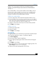
conventions
The following conventions are used in this guide:
symbols
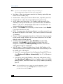
The > symbol guides you through a series of software steps. For example:
Click Start > Settings > Control Panel to view the active control panels.
warnings
A Warning indicates possible damage to the HP Gateway or to other equipment. A Warning can also
indicate a possible harm to yourself or to others.
For example:
Warning: Plugging into a nongrounded electrical socket can damage your
Gateway.
Copyright 2001 Hewlett-Packard Company
2
contents
introduction ............................................................. 5
hp digital home networking wireless gateway .................... 5
features ......................................................................... 6
getting to know the wireless gateway ......................... 7
wireless gateway rear panel ............................................ 7
wireless gateway’s front panel LEDs .................................. 9
setting up a wireless network.......................................... 10
gateway system tray application .............................. 11
overview...................................................................... 11
status notification windows............................................. 13
pop-up menu ................................................................ 16
gateway control panel ............................................ 29
overview...................................................................... 29
accessing the gateway control panel............................... 30
gateway control panel screen......................................... 33
gateway control panel tabs ............................................ 34
frequently asked questions (FAQs) ............................ 39
gateway general information.......................................... 39
wireless networking information...................................... 41
installation and configuration options .............................. 42
supported software ....................................................... 44
supported features ........................................................ 46
upgrade information ..................................................... 47
3
wireless gateway
troubleshooting ...................................................... 49
appendix: the expert interface ................................. 51
advanced administration ............................................... 51
screens and functions .................................................... 52
setup ........................................................................... 53
setting WEP encryption.................................................. 56
password..................................................................... 59
status........................................................................... 61
DHCP.......................................................................... 63
log.............................................................................. 65
help ............................................................................ 66
advanced .................................................................... 67
specifications......................................................... 79
general........................................................................ 79
environmental............................................................... 80
glossary ................................................................ 81
index .................................................................... 91
regulatory notices................................................... 93
4
introduction
hp digital home networking wireless gateway
Congratulations on your purchase of the HP Digital Home Networking Wireless
Gateway. The Wireless Gateway is the perfect solution for connecting your wireless
network to a high-speed broadband cable modem or Digital Subscriber Line (DSL)
Internet connection.
Your Gateway can be configured as a Dynamic Host Configuration Protocol
(DHCP) server, which means that it can automatically assign Internet Protocol (IP)
addresses to PCs in your Local Area Network (LAN). The Gateway becomes your
only visible network device on the Internet.
The Gateway also serves as your Internet firewall, protecting your networked PC’s
from access by external users. All incoming data is monitored and filtered using a
firewall. You can configure your Gateway to permit playing Internet games and
video conferencing. You also can use IP filtering to block your users from access to
the Internet as needed. Now all of your network users can enjoy fast broadband
Internet access and can share internal data.
A typical gateway (router) relies on a hub or switch to share its Internet connection,
but the HP Wireless Gateway, in addition to its wireless capabilities, also channels
the Internet connection through the full duplex speed of its built-in Ethernet 4-port
switch. This combination of wireless gateway and switch technology eliminates the
need to buy an additional hub or switch and extends the range of your wireless
network. Now your entire wireless network can enjoy fast broadband Internet
connections supported by its robust switched backbone. With the dual-function
speed and power of the Wireless Gateway, your network will operate faster than
you ever imagined.
5
wireless gateway
features
❑
Allows shared Internet access with all PCs on a Local Area Network (LAN)
❑
Compatible with other wireless equipment that is IEEE 802.11b (DSSS)
2.4 GHz compliant
❑
Provides filtering for roaming, best access point selection, load balancing, and
network traffic
❑
Provides wide operating range: up to 91 meters indoors or up to 457 meters
outdoors
❑
Provides up to 128-bit Wired Equivalent Privacy (WEP) encryption
❑
Allows Media Access Control (MAC) address and internal Internet access
filtering
❑
Connects to a broadband modem (DSL or cable), a 10/100 Ethernet network,
and a wireless network
❑
Allows configuration through the Web browser of your networked personal
computer
❑
Supports Internet Protocol Security (IPSec) pass-through and Point-to-Point
Tunneling Protocol (PPTP)
❑
Functions as a Dynamic Host Configuration Protocol (DHCP) server for your
existing network if desired
6
getting to know the wireless
gateway
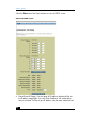
wireless gateway rear panel
All Gateway connections are made on the rear panel.
Wireless Gateway Rear Panel
1
WAN
2
3
LAN
4
UPLINK
POWER
RESET
wireless gateway ports
WAN
You will connect the DSL or cable modem
to the Wide Area Network (WAN) port.
LAN Ports 1–4
You can connect devices on your LAN,
such as PCs and print servers, to the four
LAN ports.
7
wireless gateway
Uplink Port
You can connect a cable from another
switch, router, or hub to the Uplink port to
add it to your network. Since the Uplink
port shares wiring with LAN Port 4, port 4
will be disabled if a cable is plugged into
the Uplink port (and vice versa).
Power
You will connect the included AC Power
Adapter to the Power port.
Antenna Jacks
Connect the included antennas to the
antenna jacks.
reset button
To refresh Gateway connections and attempt to fix routing problems, very briefly
depress the Reset button with a paper clip.
If you have exhausted all troubleshooting options (see the Troubleshooting section of
this user’s guide) and continue to experience serious routing problems, depress the
Reset button for about five seconds to clear all of the Gateway data and restore
the factory default settings.
Warning: Resetting the Gateway may create conflicts between your PC’s actual IP
addresses and what the Gateway expects them to be. You may be forced to restart the
entire system.
If the Gateway locks up, unplug the Power Adapter from the Gateway’s Power Port
for 3 to 5 seconds (but not longer) and then plug it back in. Leaving the power off
for too long could result in the loss of network connections.
8
wireless gateway’s front panel LEDs
wireless gateway’s front panel LEDs
Wireless Gateway’s Front Panel LEDs
WLAN
LAN 1
2
3
4
WAN
LINK
POWER
LAN indicators
WLAN
Green. The Wireless LAN (WLAN) LED
lights green when there is wireless activity.
Link
Green. The Link LED lights when the
wireless option is enabled. When the
wireless option is disabled through the
Web-based Utility, the LED is off.
Power
Green. The Power LED lights when the
Gateway is powered on. There is no
ON/OFF switch; simply plug or unplug the
power to turn Gateway on or off.
LAN
Green. If the LAN LED is continuously lit,
the Gateway is successfully connected to
the device plugged into that port (1, 2, 3,
or 4). If the LED is flickering, the Gateway
is actively sending or receiving data
through that port.
WAN
Green. The WAN LED lights when a
successful connection is made between the
Gateway and the Internet through your
broadband modem.
9
wireless gateway
setting up a wireless network
network topology
A wireless Local Area Network (LAN) uses a wireless adapter to connect each
computer to the network. Computers in a wireless network must be configured to
share the same radio channel.
The Wireless USB Network Adapter provides wireless computers access to a wired
network. This integrated wireless and wired network is called an “infrastructure”
configuration. A group of wireless-network-adapter-equipped computers plus a
wireless access point, such as the HP Wireless Network Access Point, is called a
Basic Service Set (BSS). The wireless access point connects the wireless network to
the conventional wired network. Each wireless-adapter-equipped computer can
communicate with any computer in a wired network infrastructure via the wireless
access point.
An infrastructure configuration doubles the effective wireless transmission range of
two wireless-adapter-equipped PCs since the wireless access point forwards data
within the network. It is essential to use a unique ID (a BSSID, or simply, an SSID)
within a wireless network. All PCs within an independent wireless network that are
configured without roaming options (see Roaming below) must be configured with
the same wireless network ID.
The wireless network infrastructure configuration is appropriate for enterprise-scale
wireless access to a central database and for mobile users.
roaming
Infrastructure mode also supports roaming capabilities for mobile users. Multiple
wireless network can be configured as an “extended” wireless network, known as
an Extended Service Set (ESS), allowing users to roam freely within it. All wirelessadapter-equipped PCs within one extended network must be configured with the
same extended network ID (an ESSID, or taken generically with a BSSID as
discussed above, often called an SSID,) and must use the same radio channel.
Before enabling an extended wireless network with roaming capability, select a
feasible radio channel and an optimal location for the wireless access point. Proper
wireless access point positioning and a clear radio signal will enhance
performance.
10
gateway system tray application
overview
The Gateway installation wizard installed an application on your computer that
functions as a tool kit for your Gateway. The application is accessed from a green,
red, or yellow house icon in the Windows System Tray. The Window System Tray is
in the recessed area of the Windows taskbar in the lower right of your screen.
If you did not authorize installation of the icon during Gateway installation, or if
you deleted the icon by choosing Exit from the pop-up menu, you can reinstall the
icon from the Windows Start menu. Click Start > Programs > HP Digital
Home Networking > Gateway System Tray Application. You can access
the System Tray application from any computer on your network.
The color of the house icon (green, red, or yellow) reflects the status of the network’s
Internet connection and your computer’s ability to communicate with the Gateway:
❑
Green: all is well This computer is connected to the home network with an
active Internet connection.
Gateway System Tray icon (green)
❑
Red: no Internet connection This computer is connected to the home
network, but there is no active Internet connection.
Gateway System Tray icon (red)
11
wireless gateway
❑
Yellow: connection to Gateway lost This computer is no longer
connected to the home network or to the Internet.
Gateway System Tray icon (yellow)
Besides providing constant feedback through the icon color, the Gateway System
Tray application provides additional functionality:
❑
If there is any change in network status, a status notification window appears
on your screen describing the changed situation.
❑
Right-click the Gateway System Tray icon to bring up a menu allowing you to
access the Gateway Control Panel, generate special status or diagnostic
reports, download and install software or firmware upgrades, and launch
additional Gateway utilities.
12
status notification windows
status notification windows
Any change in network status generates a status notification window describing the
change and, if needed, suggests actions to take. The change may also cause a
color change in the System Tray icon. (These same windows appear when you
select Get current network status from the System Tray pop-up menu. If all the results
are "ok", the utility has not detected any connection problems. If you do receive an
error message, however, see the table “Internet Connection Diagnostic” on
page 25 for more information.)
Note: This automatic notification feature is controlled by a toggle option in the
System Tray pop-up menu described in “Notify me when network events occur” on
page 27.
The following are examples of status notification windows, along with explanatory
comments (notice that the color of the house icon on the screen matches the color of
the icon on the System Tray):
Internet Connection Down
13
wireless gateway
This window appears when the Gateway attempts to access the Internet and cannot
detect a connection.
Connection to Gateway Lost
This window appears when your computer cannot establish a link to the Gateway.
Caution: If you reset the Gateway, be sure to do so only briefly (a second or
two) or the Gateway will be reset to the factory defaults and any modifications
you have made will be lost.
14
status notification windows
Internet Connection Operational
This window appears when the Internet connection is restored. It also appears
when when you first start your computer.
15
wireless gateway
pop-up menu
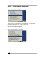
Right-clicking the Gateway System Tray icon to display the following pop-up menu:
Gateway System Tray pop-up menu
This menu provides convenient access to Gateway tools, which are described in this
section.
Accessing a menu choice:
1 Right-click the icon, move cursor to highlight the desired option.
2 Highlight the desired option.
3 Left-click the option to launch it.
16
pop-up menu
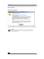
Check for upgrade
Check for upgrade...
When a software or firmware upgrade becomes available on the HP Web site, you
are notified automatically by a notification window (assuming you have enabled
this option — see “Notify me when network events occur” on page 27) and
prompted to download and install the upgrade.
Since the automatic notification may not be as frequent as you would like, you can
also manually check for the availability of upgrades by selecting Check for
upgrade... from the System Tray application pop-up menu. The application
checks the HP Web site, determines which upgrade (if any) is available for your
configuration, gives you an opportunity to confirm that you wish to download and
install the upgrade, and performs the download and installation of your new
software or firmware upgrade.
17
wireless gateway
Internet speed meter
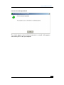
Internet speed meter...
Selecting Internet speed meter... launches a utility that monitors your upstream
and downstream Internet connection speed. When you select this choice, the
following window appears:
speed meter start window
Click Start, and the following window appears displaying the speed of your
Internet connection (it may take a few seconds to display both downstream and
upstream parameters). With DSL, the downstream speed (the speed data is
downloaded from the Internet to your computer) is typically much faster than the
18
pop-up menu
upstream speed (the speed at which data is uploaded from your computer to the
Internet), as shown in the example. Contact your DSL or broadband cable provider
for specifications.
speed meter report
Gateway control panel
Gateway control panel...
The Gateway Control Panel allows you to adjust the settings of your Gateway.
Access to the Control Panel requires the Gateway’s administrative password.
19
wireless gateway
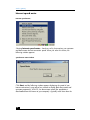
Save the current Gateway configuration
Save the current Gateway configuration...
This option provides a backup copy of your current Gateway settings in the event
that you need to restore them. This is especially useful if you modify your settings
using the Gateway Control Panel, upgrade Gateway software or firmware, or
experience a system crash.
1 Select Save the current Gateway configuration… The following screen
appears:
Save configuration backup file location
20
pop-up menu
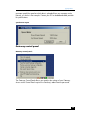
2 Click Browse to select a location to store the Gateway configuration backup
file. The following dialog box appears:
Choose location for configuration backup file
3 Navigate to a location of your choice for the backup file, or accept the default.
4 Click Save to save the file. The file is identified by a date and time, so you can
save a series of different configurations if desired.
Note:
It is recommended that you save the current Gateway configuration on a
diskette for safekeeping after installing the Gateway.
21
wireless gateway
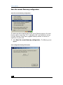
Restore a previous Gateway configuration
Restore a previous Gateway configuration...
Select this choice to restore a previously saved configuration. If you have saved
more than one configuration, you can select a specific one.
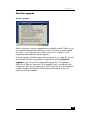
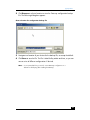
Internet connection diagnostic
Internet connection diagnostic... menu choice
22
pop-up menu
This utility checks your Internet connection to identify problems when a loss of
connection occurs. Select the Internet connection diagnostic... to display the
Internet connection diagnostic start window:
Internet connection diagnostic start window
The utility checks for Internet connections via the Gateway or directly from your
computer.
23
wireless gateway
Click Start to begin the diagnostic routine. The Internet Connection Diagnostic
screen appears:
Internet connection diagnostic report window
24
pop-up menu
If all results are “ok”, the utility has not detected any connection problems.
Internet Connection Diagnostic
Parameter
Message
Meaning
Connection to the
Gateway
Failed
Requires a “soft” reset of
the Gateway. Depress the
Reset button briefly (one or
two seconds) with a
paperclip. Depressing the
Reset button longer that
two seconds can cause the
factory default settings to
activate.
Connection to the Internet
via Gateway (Ping)
Failed
Contact your ISP.
Connection to the Internet
(Ping)
Failed
Contact your ISP.
Ping primary DNS
Failed
Contact your ISP.
Interpreting a “failed” report for any parameter:
❑
Connection to the Gateway. “Failed” means you should perform a soft reset of
your Gateway. To do this, briefly depress the Reset button (only a second or
two) on your Gateway with a paper clip or pencil tip. Be careful not to hold it
down any longer than one to two seconds or the Gateway will be reset to the
factory defaults and any modifications you have made will be lost.
❑
Connection to the Internet via Gateway. “Failed” means you should contact
your Internet service provider (ISP).
❑
Connection to the Internet. “Failed” means you should contact your Internet
service provider.
❑
Ping primary DNS. “Failed” implies an Internet Service Provider problem.
Contact your ISP to report the problem.
25
wireless gateway
Get current network status
Get current network status...
Selecting this choice generates one of the status notification windows discussed and
illustrated in the section “status notification windows” on page 13. If all is well and
the diagnostic utility detects no changes, the window appears:
example of a current network status window
26
pop-up menu
Notify me when network events occur
Notify me when network events occur
Selecting this option displays the status notification windows discussed in “status
notification windows” on page 13. If you do not wish to receive these notifications
select it and verify that the checkmark no longer appears next to this option (if a
checkmark is present, make the selection again).
About HP Digital Home Networking
Selecting this option displays a window giving the version number of the Gateway
System Tray application.
Exit
Selecting the Exit option removes the Gateway System Tray icon from the System
Tray and prevents the program from launching when you next restart the computer.
To restore the icon to the System Tray, select Start > Programs > HP Digital
Home Networking > Gateway System Tray Application.
27
wireless gateway
28
gateway control panel
overview
The Gateway Control Panel allows you to configure additional functions beyond
those installed through the Installation Wizard. This tool is a simplified alternative to
the Expert Interface, which is described in the Appendix of this user’s guide. The
functions of the Gateway Control Panel eliminate the need to use the Expert
Interface in most cases.
However, you may wish to refer to the Appendix for supplementary information for
some of the options described in this chapter.
Caution: Only one user can access the Gateway Control Panel at a time.
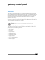
The Gateway Control Panel is a typical Windows control panel with tabs which
provide access to the following functions:
❑
My Network
❑
Password
❑
Internet Access
❑
Application Access
❑
Application Hosting
❑
Expert Interface
❑
FAQ & Troubleshooting
❑
Remote Support
29
wireless gateway
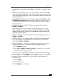
accessing the gateway control panel
The Gateway Control Panel is accessed from the Gateway System Tray icon
described in the previous chapter. It can also be accessed from Start >
Programs > HP Digital Home Networking > Gateway Control Panel.
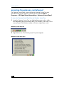
To access the Gateway Control Panel from the Windows System Tray:
1 Locate the Gateway System Tray icon (depicted as a green, red, or yellow
house depending on current network status). The Windows System Tray is in the
recessed area of the Windows taskbar in the lower right of your screen.
Gateway System Tray icon
2 Right-click the icon. The Gateway System Tray menu appears:
Gateway System Tray menu
30
accessing the gateway control panel
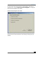
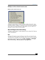
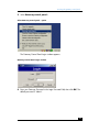
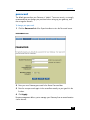
3 Select Gateway control panel...
Select Gateway control panel... option
The Gateway Control Panel Login window appears:
Gateway Control Panel Login window
4 Enter your Gateway Password in the Login Password field, then click OK. The
default password is “admin”.
31
wireless gateway
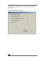
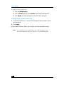
5 Click Hint on the Login screen if you cannot remember your password. The
Password Hint window appears:
Password hint window
6 The question you provided when the default password was changed is
displayed. Enter the answer in the Hint Answer field, then click OK. The Hint
reply window appears:
Hint reply window
7 Click OK, and the password will be automatically inserted into Password box.
Click OK to complete the login.
32
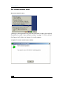
gateway control panel screen
gateway control panel screen
When you have successfully logged on, the Gateway Control Panel screen appears
with the My Network tab selected. With any tab selected, you can access all the
other functions by clicking another tab.
Apply button
You can save changes at any time by clicking the Apply button. Clicking Apply
does not close the control panel, and you can continue to use the other tabs to
make additional changes to your settings. Clicking Apply saves all the changes on
all the tabs, not just the settings on the tab you are currently modifying.
OK button
When you are finished using the control panel and wish to save any additional
changes and exit, click OK. The control panel will close and your changes will be
saved.
Cancel button
If you wish to exit the control panel without saving any unsaved changes, click
Cancel.
33
wireless gateway
gateway control panel tabs
My Network tab
This tab is a display-only overview of your network. It shows your Gateway and all
the devices connected to the network, and it shows whether each device has an
Ethernet, phoneline, or wireless connection.
The display is dynamically updated. However, click the Refresh button for the most
current information.
Password tab
The Password tab allows you to change your Gateway’s password and password
hint. It is strongly advised that you create a password hint question and answer the
first time you change your password in case you forget you password.
To change the password:
1 Click Change Password.
2 Enter the current password in the Current Password field.
3 Enter a new password in the New Password field.
4 Reenter the new password in the Confirm New Password field.
5 Click OK.
6 Click Apply to save the changes.
To change the password hint:
1 Click Change Password Hint.
2 Enter a hint question in the Hint Question field. For example, “Where was I
born?”
3 Enter the answer to the hint question in the Hint Answer field.
4 Click OK. If you forget your password while logging onto the Gateway Control
Panel, click Hint, supply the hint answer, and the existing password is
provided.
5 Click Apply to save changes.
34
gateway control panel tabs
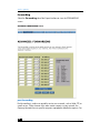
Internet Access tab
The Internet Access tab allows you to restrict specified computers on your network
from accessing the Internet. You can also allow one user to be exposed to the
Internet for a special purpose such as Internet gaming or video conferencing (the
firewall is disabled for that one user).
To block specified computers from Internet access:
1 In the Internet Access Enabled window, locate the computer of the user whom
you wish to block from Internet access.
2 Single-click that computer. To make multiple selections, hold down the Control
key while single-clicking entries.
3 Click and drag all selected computers to the Internet Access Disabled window
or click the left-pointing arrow button between the two windows.
If you change your mind or make a mistake, highlight and drag the selection
back into the center window.
4 Click Apply to save the changes.
To expose one computer to the Internet:
1 From the Internet Access Enabled window, locate the one computer you wish to
expose to the Internet.
Caution: Exposing a computer to the Internet using this option disables
firewall protection for that computer.
2 Click and drag that entry into the Unprotected PC window (or select it and click
the right-pointing arrow button.
3 Click Apply to save changes.
Application Access tab
The Application Access tab allows you to block specified computers on your local
network from access to games or other applications on the Internet.
To block access to Internet applications:
1 From the Application List window, locate the application you wish to block from
Internet access for all users on your local network.
2 Single-click that entry. To make multiple selections, hold down the Control key
while single-clicking entries.
35
wireless gateway
3 Click and drag all selected computers to the Internet Access Disabled window
or click the left-pointing arrow button between the two windows.
Note:
If an application you select shares the same port(s) with other applications, all
applications configured for those ports will be dragged along with your
selection since this operation blocks the port used by those applications, not
the application itself.
If you change your mind or make a mistake, highlight and drag applications
back into the center window.
4 Click Apply to save the changes.
Application Hosting tab
The Application Hosting tab allows you to host Internet services, e-mail, or an FTP
server on one network computer. The services must be installed on the computer.
Then access to network computers is enabled through the Applications Hosting tab.
Once enabled, all requests from the Internet for a service will be routed by the
Gateway to the computer specified. If no computer has been enabled for a service,
access to that service is blocked by the Gateway.
Some ISPs restrict hosting services. Check with your ISP before installing a hosted
service.
Positioning your cursor over one of the applications listed on the tab displays the
existing settings (port numbers and protocols) for that application.
To enable hosting of Internet services:
1 On the Application Hosting tab, locate the application you want to enable.
2 Click the Enable checkbox.
3 Select the computer on your network that will be hosting this service from the
drop-down menu.
4 Repeat for any additional applications.
5 Click Apply to save changes.
To add a new application to the list:
1 On the Application Hosting tab, click Add Application.
2 Enter the name of the application you want to add.
3 See the documentation that came with the application you wish to add for
acceptable port number (or range of port numbers) and protocols. (The preset
applications available on the the Application Hosting tab the port numbers are
already configured.)
36
gateway control panel tabs
4 Enter the port number for the application; if a range is specified, click the Enter
Port Range checkbox and enter the range of port numbers in the Starting Port
and Ending Port fields.
5 To specify the protocol, click Advanced and select among these choices:
❑
Both TCP and UDP (the default)
❑
TCP
❑
UDP
6 Click OK.
7 Click Apply to save the changes.
To remove an application from the list:
1 On the Application Hosting tab, click Remove Application(s).
2 Click the checkbox next the application you wish to remove. You can check
more than one box.
3 Click OK.
4 Click Apply to save the changes.
Expert Interface tab
This tab provides access to the Expert Interface described in the Appendix to this
user’s guide. The other tabs of the Gateway Control Panel to provide automated
access to the Expert Interface settings. Only advanced users should attempt to
access the Expert Interface directly.
To access the Expert Interface, click Launch Expert Interface.
Caution: Only one user can access the Expert Interface at a time.
FAQ & Troubleshooting tab
This tab refers you to this user’s guide, which resides on the CD-ROM provided. You
may want to refer to the following chapters:
❑
Appendix: the Expert Interface
❑
Troubleshooting
❑
FAQ
❑
Glossary
37
wireless gateway
The index will help you locate additional information related to the operation of the
Gateway Control Panel.
Remote Support tab
The Remote Support tab provides access to the HP Customer Care Web site and
also provides an opportunity for HP customer care experts to assist you directly if
you experience difficulties you cannot solve by other means. A button on the tab
takes you through the process of allowing HP Customer Care direct access to your
Gateway, which it can then configure via remote access.
38
frequently asked questions (FAQs)
gateway general information
What is Network Address Translation and what is it used for?
Network Address Translation (NAT) translates multiple IP addresses on the
private LAN to one public address that is sent out to the Internet. This adds a
level of network security since the addresses of PCs connected to the private
LAN are never transmitted over the Internet. NAT also allows the Gateway to be
used with low-cost Internet accounts, such as DSL or cable modem, where only
one Transmission Control Protocol/Internet Protocol (TCP/IP) address is
provided by the Internet Service Provider (ISP). The user may have 253 private
addresses behind this single address provided by the ISP.
What type of firewall does the Gateway have?
The Gateway uses NAT and TCP/IP port inspections.
Is the Gateway cross-platform compatible?
Any platform that supports Ethernet and TCP/IP is compatible with the
Gateway.
Does the Gateway replace a modem? Is there a cable or DSL modem in the
Gateway?
No, the Gateway must work in conjunction with a cable or DSL modem.
Which modems are compatible with the Gateway?
This Gateway is compatible with virtually any cable or DSL modem that
supports Ethernet.
How can I check whether I have static or DHCP IP Addresses?
Consult your ISP to obtain this information.
How do I get mIRC to work with the Gateway?
On the PC on which you are using mIRC, click the Forwarding tab on the
Expert Interface and set Port forwarding to 113 (see “forwarding” on
page 70 of the Appendix: Expert Interface). If you experience difficulty after
setting port forwarding, try changing the Direct Client-to-Client (DCC) settings to
a range from 1024 to 1030 on the DCC option of the Forwarding settings
39
wireless gateway
page of the Expert Interface.
How can I block corrupted FTP downloads?
If you are experiencing corrupted files when you download a file with your FTP
client, try using another FTP program.
What is DMZ Hosting?
Demilitarized zone (DMZ) hosting allows one IP address (or computer) to be
exposed to the Internet. Some applications require multiple TCP/IP ports to be
open. It is recommended that you set your computer with a static IP address if
you want to use DMZ Hosting.
If DMZ Hosting is used, does the exposed user/PC share the public IP address with
the Gateway?
No.
Does the Gateway pass PPTP packets or actively route PPTP sessions?
The Gateway allows Point-to-Point Tunneling Protocal (PPTP) packets to pass
through.
40
wireless networking information
wireless networking information
Can I run an application from a remote computer over the wireless network?
This depends on whether the application is designed to be used over a network.
Consult the application’s user’s guide to determine if it supports operation over
a network
Can I play computer games with other members of the wireless network?
Yes, as long as the game supports multiple players over a LAN. Refer to the
game’s user’s guide for more information.
What is the IEEE 802.11 standard?
The IEEE 802.11 Wireless LAN Standards Subcommittee of the Institute of
Electrical and Electronics Engineers (IEEE) is formulating a standard for the
industry to enable wireless LAN hardware from different manufacturers to
communicate with one another.
What IEEE 802.11 features are supported?
HP wireless products support the following IEEE 802.11 functions:
❑
Carrier Mulitiple Sense Access/Collision Detect (CMSA/CA) plus the
Acknowledge protocol
❑
Multi-channel roaming
❑
Automatic rate selection
❑
Request-to-send/ Clear-to-send (RTS/ CTS)
❑
Fragmentation
❑
Power management
Would information be intercepted while transmitting on air?
Wireless LAN features two-fold security protection. On the hardware side, as
with Direct Sequence Spread Spectrum (DSSS) technology, it has the devices
have the inherent scrambling security feature. On the software side, wireless
LAN offers Wired Equivalent Privacy (WEP) encryption to enhance security and
access control.
41
wireless gateway
installation and configuration options
How many IP addresses can the Gateway support?
The Gateway supports a maximum of 253 IP addresses.
Where is the Gateway installed on the network?
In a typical environment, the Gateway is installed between the modem and the
LAN. Plug the Gateway into the cable or DSL modem's Ethernet port.
Does the Gateway support any operating system other than Windows 95, 98, Me,
2000, NT, or XP?
Yes, but Hewlett-Packard does not provide technical support for setup,
configuration, or troubleshooting of any non-Windows operating systems at this
time.
If all else fails in the installation, what can I do?
Reset the Gateway by depressing the Reset button for at least three seconds,
then reset your cable or DSL modem by powering the unit off and then back on.
Obtain and flash (upload) the latest firmware release from the Hewlett-Packard
Web site (www.hp.com).
Does the Gateway function in a Macintosh environment?
Yes, but the Gateway's setup pages are accessible only through Internet
Explorer v4.0 or Netscape Navigator v4.0 or higher for Macintosh PCs.
I cannot get the Web configuration screen for the Gateway. What can I do?
You may have forgotten to remove the proxy server settings on your Internet
browser, such as Netscape Navigator or Internet Explorer. Or, remove the dialup settings on your browser. Check your browser documentation.
Will the Gateway allow me to use my own public IP addresses and domain, or do I
have to use the IP addresses provided by the Gateway?
The Gateway mode allows customization of your public IP addresses and
domain.
How many ports can be simultaneously forwarded?
Theoretically, the Gateway can establish 520 sessions at the same time, but you
can only forward 10 ranges of ports.
42
installation and configuration options
What is the maximum number of virtual private network (VPN) sessions allowed by
the Gateway?
One VPN session at a time; the memory buffer on the Gateway is 512 KB.
My Web pages hang up, I get corrupted downloads, or junk characters are being
displayed on the screen. What do I do?
Force your Ethernet network interface card (NIC) to 10 Mbps or half duplex
mode and turn off the Autonegotiate feature temporarily (go to the Network
Control Panel in your Ethernet Adapter's Advanced Properties tab). Check with
your NIC manufacturer for more information.
43
wireless gateway
supported software
Does the Gateway support ICQ send files?
Yes, with the following fix: from ICQ menu > preference > connections tab >,
select I am behind a firewall or proxy and set the firewall time-out to 80
seconds in the firewall setting. The Internet user can then send a file to a user
behind the Gateway.
How do I get Napster to work with the Gateway?
Napster is fully compatible with the Gateway. During installation select no
idea when asked about your firewall settings. Set your proxy settings to No
Proxy Server in File>Preferences.
I set up an Unreal Tournament server, but others on the network cannot join. What
do I do?
If you are running a dedicated Unreal Tournament (UT) server, you must create
a static IP address for each of the network PCs and forward ports 7777, 7778,
7779, 7780, 7781, and 27900 to the IP address of the server. If you want to
use the UT server admin, forward another port (8080 usually works well), then
in the [UWeb.WebServer] section of the server.ini file, set the ListenPort to 8080
to match the mapped port above and ServerName to the IP assigned to the
Gateway from your ISP.
Can multiple gamers on the LAN log on to one game server and play simultaneously with just one public IP address?
It depends on which network game you’re playing and what kind of game
server you’re using. For example, UT supports multi-login with just one public IP
address.
How do I get Half-Life:Team Fortress to work with the Gateway?
The default client port for Half-Life is 27005. The PCs on your LAN must have
“+clientport 2700x” in the HL shortcut command line; the x would be 6, 7, 8,
and on up. This allows multiple PCs to connect to the same server. One
exception: version 1.0.1.6 won't let multiple PCs with the same CD key connect
at the same time, even if they’re on the same LAN (it’s not a problem with
version 1.0.1.3). For hosting games, the HL server does not need to be in the
DMZ. Just forward port 27015 to the local IP of the server PC. There remains,
however, a problem with people being booted after a few minutes with an
illegible server message.
44
supported software
Does the Gateway support IPsec?
A new IPsec pass-through feature is now included.
45
wireless gateway
supported features
What are the advanced features of the Gateway?
The Gateway's advanced features include IP filtering, IP forwarding, dynamic
routing, static routing, DMZ hosting, and MAC address cloning.
Is IPSec Pass-Through supported by the EtherFast Gateway?
Yes, it is a built-in feature that the Gateway automatically enables.
Does the Gateway support IPX or AppleTalk?
No. TCP/IP is the only protocol standard for the Internet and has become the
global standard for communications. Internet Packet eXchange (IPX), a
NetWare communications protocol used only to route messages from one node
to another, and AppleTalk, a communications protocol used on Apple and
Macintosh networks, can be used from LAN to LAN connections, but those
protocols cannot connect from WAN to LAN.
Does the WAN connection of the Gateway support 100 Mbps Ethernet?
Since broadband Internet connections like cable and DSL do not exceed 10
Mbps, the Gateway’s current hardware design only supports 10 Mbps Ethernet
on its WAN port. It does support 100 Mbps through the built-in auto-sensing
Fast Ethernet 10/100 switch on the LAN side of the Gateway.
Does the Gateway support SPI?
Stateful packet inspection (SPI) is a new feature of the Gateway.
46
upgrade information
upgrade information
How will I be notified of new Gateway firmware upgrades?
All Hewlett-Packard firmware upgrades are posted on the HP website at
www.hp.com, where they can downloaded for free. The Gateway's firmware
can be upgraded with Trivial File Transfer Protocol (TFTP) programs. If your
Gateway’s Internet connection is working well, there is no need to download a
newer firmware version unless that version contains new features that you would
like to use. Downloading a more current version of Gateway firmware will not
enhance the quality or speed of your Internet connection, and may disrupt your
current connection stability.
47
wireless gateway
48
troubleshooting
I can’t connect to the Gateway.
❑
Verify that the Gateway is properly installed, the LAN connections are OK (the
LAN LEDs should be lit), and it is powered on.
❑
Verify that the PC is using an IP address between 192.168.1.2 and
192.168.1.254 and thus compatible with the Gateway default IP address of
192.168.1.1.
❑
The subnet mask must be set to 255.255.255.0 to match the Gateway’s subnet
mask. Confirm these settings for the Gateway from the Windows Start button
by selecting Settings > Control Panel > Network (or Network & Dialup Connections) > Local Area Connection > Internet Protocol
(TCP/IP)/Properties.
I can’t browse through the Gateway.
❑
Verify that both ends of the Ethernet cable and power adapter are properly
connected and that the LEDs on the front panel are functioning properly.
❑
If using Windows 98 or Me, verify the TCP/IP setup on the client side. Click the
Windows Start button, select Run, type winipcfg, and click Enter. The PC
should have an IP address of 192.168.1.xxx ("xxx" is from 2 to 254), the
subnet mask should be 255.255.255.0, the default gateway IP should be the
Gateway’s IP address, and it should have DNS. If using Windows 2000, use
ipconfig to obtain this information.
❑
Also, check the same values as indicated in the previous bullet in the Setup tab
of the Gateway’s Expert Interface (see the Setup sections of the Appendix:
Expert Interface of this user’s guide.)
When I enter a URL or IP address, I get a Request timed out error.
❑
Check to see if other PCs give you the same error message. If they do, verify
that your workstations’ IP settings are correct (IP address, subnet mask, default
gateway, and DNS server).
❑
If the PCs are configured correctly but still not working, check the Gateway.
Verify that it is connected and powered on. Connect to the Gateway and check
its settings. If you cannot connect to it, check the LAN and power connections.
❑
If the Gateway is configured correctly, check your Internet connection
(broadband modem) to see that it is working correctly.
❑
Manually configure the TCP/IP with a DNS address provided by your ISP.
49
wireless gateway
I can’t obtain an IP address from my cable or DSL modem.
❑
Verify that all of your cabling is properly connected and that the Gateway’s
WAN and LAN LEDs are lighting up.
❑
Power down your cable or DSL modem for a few seconds, then turn it back on.
After the modem goes through its self-test, see if you now have an IP address.
❑
Verify that your cable or DSL modem is DHCP-capable.
❑
You may have to enter the host or domain name on the Setup page of the
Gateway’s Expert Interface. See “setup” on page 53 of the Appendix: Expert
Interface.
❑
Your ISP may require MAC Addresses. Check with your ISP. This MAC address
can be obtained on the Status screen of the Gateway’s Expert Interface.
I can’t get a link to a modem, hub, or switch for one of my ports.
❑
Verify that your cabling is undamaged and is connected properly.
❑
Verify that your network interface adapter has been properly installed.
❑
Verify that both the Gateway and the other device are powered on.
❑
If you are linking to a hub or a switch, be sure that the other device is
functioning properly.
❑
If you are connecting to a cable modem, try plugging it into the Gateway’s
uplink port rather than into a LAN port.
❑
If all else fails, reset the Gateway by depressing the Reset button with a paper
clip. If you continue to experience serious routing problems, depressing the
Reset button for about five seconds will clear all of the Gateway data and
restore the factory default settings. However, be cautious before resetting the
Gateway since doing so risks creating conflicts between your PCs’ actual IP
addresses and what the Gateway expects them to be, and you may be forced
to restart the entire system.
I can’t access my e-mail or the Internet.
❑
Some ISPs, especially cable providers, configure their networks so that you
don’t have to enter a full Internet address into your Web browser or e-mail
application to reach your home page or receive your e-mail.
❑
You must obtain this information before connecting the Gateway to your
network: ask your ISP.
50
appendix: the expert interface
advanced administration
For your convenience, a Web-based administrative utility called the Expert Interface
has been programmed into your Gateway. Advanced Gateway administrative tasks
may be performed through this interface. The Expert Interface may be accessed
through any computer on the network by typing http://192.168.1.1 in the
address box of your Web browser (such as Internet Explorer or Netscpe Navigator)
and pressing Enter. The Enter Network Password dialog box appears.
Enter Network Password dialog box
1 Leave the User Name field blank.
2 Type admin into the Password field.
Note:
"admin" is the default password. We recommend that you change this
password periodically by following the directions in the Password section of
this Appendix.
3 Click OK.
51
wireless gateway
screens and functions
The following pages contain descriptions of each screen and its functions. The
screens described are:
❑
Setup
❑
Password
❑
Status
❑
DHCP
❑
Log
❑
Help
❑
Advanced: The Advanced screen contains links to the following advanced
settings screens:
❑
Filters
❑
Forwarding
❑
Dynamic Routing
❑
Static Routing
❑
DMZ Host
❑
MAC Clone
Similar explanations and instructions to the material in this guide can be found by
clicking each screen’s Help button (or the Help tab). To clear any values entered
on a page, click Cancel and reenter the information. To save any settings altered
on a page, click Apply. From any screen, click a new tab to access additional
settings screens.
52
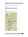
setup
setup
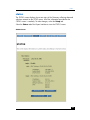
The SETUP screen appears when the Expert Interface is accessed.
SETUP Screen
53
wireless gateway
Note:
If you have used the Installation Wizard to install your Gateway, you
have already properly configured all of this screen’s initial settings.
❑
Host Name: Allows you to create a name for the Gateway, required by some
Internet Service Providers (ISPs).
❑
Domain Name: Allows you to create a domain name, required by some ISPs.
❑
Firmware Version: Shows the version of the firmware you are using.
❑
LAN IP Address and Subnet Mask: The IP address and subnet mask of the
Gateway as seen by internal LAN users in your home or office. The default IP
address is 192.168.1.1 and the default subnet mask is 255.255.255.0. It is
recommended that you keep the defaults.
❑
Wireless: Select Enable to use Gateway’s wireless functions. Select Disable
if no wireless functions are used.
❑
ESSID: The unique name shared among all points in a wireless network. It must
be identical for all points in the network, is case sensitive, and must not exceed
32 characters.
❑
Channel: Select the appropriate channel (1 to 11) from the list that corresponds
to your network settings. All points in your wireless network must use the same
channel in order to function correctly.
❑
Wired Equivalent Privacy (WEP): Select Mandatory to utilize WEP
encryption. Select Disable if no WEP functions are used. When WEP
encryption is enabled, click WEP Key Setting and follow instructions for
“setting WEP encryption” on page 56.
❑
WAN IP Address: Displays the Media Access Control (MAC) address of the
Gateway and controls the IP address and subnet mask of the Gateway as seen
by external users on the Internet.
❑
If your ISP is running a Dynamic Host Configuration Protocol (DHCP) server,
select Obtain an IP Address Automatically. Your ISP will allocate an
IP address.
❑
If you have a static (fixed) IP address, subnet mask, and gateway setting
select Specify an IP address. Enter the IP address, subnet mask, default
gateway address, and Domain Name Server (DNS) IP address provided by
your ISP.
Note:
54
You can verify that your various settings are correct by attempting to connect
to the Internet as follows: type www.hp.com into the address window of
your Web browser and press Enter.
setup
❑
Login PPPoE: Check with your ISP to determine whether Point-to-Point Protocol
over Ethernet (PPPoE) should be enabled. If PPPoE should be enabled:
1 Select PPPoE as the login method.
2 Enter the User Name and the Password as specified by your ISP.
3 Select one of the following:
❑
Connect on Demand to connect/disconnect the PPPoE connection
automatically.
The PPPoE connection will be disconnected if it has been idle longer
than the Max Idle Time setting (recommended settings are 0 or 9999 for
best connection reliability). If you have been disconnected due to
inactivity, Connect on Demand enables your Gateway to automatically
reestablish your connection as soon as you attempt to access the Internet
again.
❑
Keep Alive to keep the Internet connection alive indefinitely.
The gateway keeps the Internet connection alive indefinitely by sending
out a few data packets periodically so your Internet service detects that
the connection is still active. If you enable PPPoE, remember to remove
any existing PPPoE applications already on any of your PCs. (Disregard
RAS Plan which is for RAS only.)
If PPPoE should not be enabled: Select Disable.
❑
Login RAS (Singapore only): SingTel Magix uses Alcatel Remote Access
Service (RAS) as the main authentication method for its Asymmetric Digital
Subscriber Line (ADSL) servers in Singapore. This method uses TCP port 5555.
To enable RAS:
1 Select RAS as the login method, then enter your user name.
Note:
A 512K user should use one of the following formats: username or
username@INT512.
2 Enter your password and select your RAS Plan.
3 To check your RAS status select the Status tab. (Disregard Connect on
Demand and Keep Alive, which are for the PPPoE option only.)
Click Apply to save settings.
55
wireless gateway
setting WEP encryption
Note:
WEP Encryption is an additional data security measure that is not
essential for Gateway operation.
Wired Equivalent Privacy (WEP) encryption is a method of encrypting data
transmitted over a wireless network to insure data security. In a wired network, data
security is maintained through the physical wire. WEP encryption provides the same
level of security for wireless data as if transmitted over standard network cabling.
In order to duplicate wired network security levels, wireless data is encrypted at the
point of transmission and decoded by the receiving device, allowing users to have
the same amount of security over their wireless network as they would over a wired
network. This level of security is in addition to that already provided by the
password protection of your network operating system.
The present standard for this encryption as set by the Institute of Electrical and
Electronics Engineers is defined as 40-bit (sometimes also called 64-bit) encryption.
These numbers refer to the complexity of the algorithms generated in order to code
and decode the data transmitted. The higher the bit number, the greater the
complexity of the algorithm and the more secure the encryption.
Higher levels of encryption often negatively affect network data transmission rates.
This encryption is not necessary for the operation of your wireless network device. If
ordinary password protection is sufficient, disregard WEP encryption. However, if
password prtection is not sufficient, then enable WEP encryption.
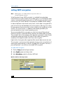
To enable WEP encryption:
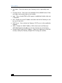
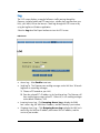
1 Click the Setup tab of the Expert Interface
2 Select Enable under the Wireless field.
3 Select Mandatory under the Wireless WEP field.
Wireless Field on the Setup Screen
56
setting WEP encryption
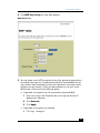
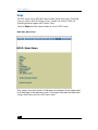
4 Click WEP Key Setting; the Web Table appears.
WEP Table Screen
5 You may create a new WEP encryption key by either generating a passphrase
or manually entering a key. The passphrase method is recommended, but you
may need to create a manual key to meet the requirements of existing wireless
equipment on your network. Check your documentation or with your system
administrator. Choose one of the following options:
❑
To generate an encryption key with a passphrase (recommended):
1 Enter a text string in the Passphrase box; the string may be up to 31
alphanumeric characters.
2 Click Generate.
3 Click Apply.
❑
To generate an encryption key manually:
1 Fill in keys 1 through 4.
57
wireless gateway
2 Click Apply.
Commit the passphrase or manual key to memory since you will probably need it
for other wireless devices on the network.
58
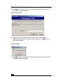
password
password
The default password on your Gateway is “admin”. To ensure security, we strongly
recommend that you change your password when setting up your gateway, and
then at regular intervals.
To change your password:
1 Click the Password tab of the Expert Interface to view the Password screen.
PASSWORD Screen
2 Enter your new Gateway password in the Router Password box.
3 Enter the new passwork again in the second box exactly as you typed it in the
first box.
4 Click Apply.
Remote management allows you to manage your Gateway from a remote location
via the Internet.
59
wireless gateway
To enable remote management:
1 Click the Advanced tab.
2 Click the Filters tab and select Enable under Remote Management.
3 Click Apply. A remote managment password will be assigned.
To change remote management password:
1 On the Password screen, in the Remote Management Password box, enter a
new password.
2 Click Apply.
Restore Factory Defaults: Allows you to restore the Gateway default settings.
Note:
60
If you set the Restore Factory Default option to Yes and click Apply, you will
clear all of the Gateway’s settings. You will have to set up the Gateway again.
status
status
The STATUS screen displays the current status of the Gateway, reflecting data and
selections entered on the SETUP screen. All of the information provided on the
STATUS screen is read-only. To make changes, select the Setup tab.
Select the Status tab of the Expert Interface to view the STATUS screen.
STATUS Screen
61
wireless gateway
❑
Host Name: Shows the name of your Gateway, which is required by some
ISPs.
❑
Firmware Version: Shows the version and date of the installed firmware. Dates
are slightly more accurate than version numbers.
❑
Login: Shows whether PPPoE or RAS support is enabled and whether either one
is connected.
❑
LAN: Displays the current IP address and subnet mask of the Gateway as seen
by users on your LAN.
❑
DHCP Server: Shows whether the Gateway's DHCP server is either enabled or
disabled.
❑
WAN: Displays the WAN IP address, WAN subnet mask, and Gateway’s
WAN default gateway IP address as seen by external users on the Internet.
❑
Domain Name System (DNS) IP Address: Shows the IP address(es) of the DNS
currently used by the Gateway. Multiple DNS IP settings are common.
62
DHCP
DHCP
A Dynamic Host Configuration Protocol (DHCP) server automatically assigns IP
addresses to each computer on a network. Unless you already have a DHCP server
on your network, it is highly recommended that your Gateway be set up as a DHCP
server.
Select the DHCP tab of the Expert Interface to view the DHCP screen.
DHCP Screen
❑
DHCP Server: Select Enable to enable the Gateway’s DHCP server option. If
you already have a DHCP server on your network, select Disable. If you
disable DHCP, remember to assign a static IP address that is in your local
subnet.
❑
Starting IP Address: Enter an initial IP address (or accept the default) for the
DHCP server when issuing IP addresses. Since the default IP address for your
63
wireless gateway
Gateway is 192.168.1.1, the starting IP address must be 192.168.1.2 or
greater.
❑
Number of DHCP users: Enter the maximum number of devices to which you
want the DHCP server to assign IP addresses. Accept the default value or you
may enter a number up to a maximum of 253. The maximum number depends
on the starting IP address, so the total number must be chosen such that the
starting IP address + the number of DHCP users – 1 is equal to or less than 254
(which is the maximum value).
❑
DHCP Clients Table: Click DHCP Clients Table to show current DHCP client
information. This information is stored in temporary memory since it changes
periodically, so the list of clients could disappear, as shown on the following
screen:
DHCP Clients Table Screen
64
log
log
The LOG screen displays a record of all access traffic passing through the
Gateway, including e-mail and FTP tranmissions, whether they originate from your
LAN, your WAN, or from the Internet. Check logs through the LOG screen or by
using the LogViewer Windows application.
Select the Log tab of the Expert Interface to view the LOG screen.
LOG Screen
❑
Access Log: Select Enable to activate.
❑
Send Log To: The Gateway can send log messages to the LAN host. To launch
LogViewer to record log messages:
1 Choose a PC located on your LAN.
2 Enter the selected PC's IP address in the Send Log to box. The Gateway will
then send the log messages to that PC. Otherwise, it will send log messages
to the default IP address, 255.
❑
Incoming Access Log: Click Incoming Access Log to display the WAN
host's access log, the WAN host IP address, and the Gateway's port number.
❑
Outgoing Access Log: Click Outgoing Access Log to display the LAN host's
access log, the LAN host IP address, destination URL or IP address, and the
service or port number.
65
wireless gateway
help
The HELP screen links to all of the Expert Interface online help screens. Each help
screen, as well as all of the settings screens, contain links to the HP Web site
(including technical support and Customer Care).
Select the Help tab of the Expert Interface to view the HELP screen.
HELP: Main Menu Screen
Each settings screen also contains a Help button at the bottom of each page linked
to the help page for that particular screen. Selecting the Help tab at the top of each
settings screen takes you to this HELP menu screen.
66
advanced
advanced
The Advanced screen provides access to six settings screens: Filters, Forwarding,
Dynamic Routing, Static Routing, DMZ Host, and Mac Clone.
Select the Advanced tab of the Expert Interface to view the ADVANCED screen.
filters
Filters settings allow you to configure the Gateway to block selected users who are
configured on this network from accessing the Internet. You can set up different
filters for different users based on their IP addresses, their network port numbers, or
their physical addresses. You can also enable Virtual Private Networking (VPN)
sessions.
67
wireless gateway
Select the Filters tab of the Expert Interface to view the FILTERS screen.
Advanced: FILTERS Screen
❑
68
Filtered Private IP Range: Enter the range of IP addresses desired to filter into
the IP address range fields. Users with these IP addresses will not be able to
access the Internet. To filter only one IP address, enter the same number desired
advanced
in both boxes. For example, if the IP address is 192.168.1.5, enter 5 in each
box.
❑
Filtered Private Port Range: Filter users by entering their network port numbers.
Select the protocols and enter the range of port numbers that you want to filter
into the port number range fields. Users with these port numbers will not be able
to access the Internet.
❑
Private MAC Filter: Filter users by entering their physical MAC addresses. Click
Edit MAC Filter Setting and enter the MAC addresses desired to filter into
the MAC address fields. Users with these MAC addresses will not be able to
access the Internet.
❑
Stateful Packet Inspection (SPI): The Gateway supports SPI. Select either
Enable or Disable.
❑
Block WAN Request: Prevents hackers from attacking through the Internet.
When enabled, the Gateway will drop unaccepted TCP requests and ICMP
packets from the Internet. Hackers will not be able to locate the Gateway by
pinging the WAN IP address.
❑
IPSec Pass Through: The Gateway supports IPSec pass-through. Select either
Enable or Disable.
❑
PPTP Pass Through: The Gateway supports Point-to-Point Tunneling Protocol
(PPTP) pass-through, used to enable VPN sessions (but only one at a time).
Select either Enable or Disable.
❑
Remote Management: Allows you to manage your Gateway from a remote
location via the Internet. To activate the Remote Management feature:
1 Click Enable to activate.
2 Enter http://[WAN IP Address]:8080 in the address box of the Web
browser on any PC on your network.
3 Press Enter. You will be able to change any settings in the Expert Interface.
❑
Remote Upgrade: Select Disable. Remote Upgrade currently is not available.
❑
Maximum Transmission Unit (MTU): Limits the MTU of the Gateway. To
implement MTU:
1 Select Enable.
2 Enter the MTU size.
3 Click Apply to save changes.
69
wireless gateway
forwarding
Select the Forwarding tab of the Expert Interface to view the FORWARDING
screen.
ADVANCED: FORWARDING Screen
port forwarding
Port forwarding is used to set up public services on a network, such as Web, FTP, or
e-mail servers. When Internet users make certain requests to your network, the
Gateway forwards them to specific computers equipped to handle the requests. For
70
advanced
example, if you set port number 80 (HTTP) to be forwarded to IP address
192.168.1.2, then all HTTP requests from outside users will be forwarded to
192.168.1.2.
Enter a valid IP address. You may need to establish a static IP address with your
Internet provider in order to properly run an Internet server. For added security,
Internet users are able to communicate with the server but will not actually be
connected. The packets are forwarded through the Gateway.
To add a server using forwarding:
1 Enter the range of port numbers and select the protocol used by the server.
2 Enter the IP address of the server that you want the Internet users to be able to
access. Refer to your software documentation for more information concerning
which service port settings may need to be changed, if any.
3 Configure as many entries as desired up to the number of boxes provided.
4 Click Apply to save changes.
To delete a server entry:
1 Delete the port range number.
2 Delete the IP address.
3 Click Apply to save changes.
port triggering
Port triggering enables a server and LAN host to communicate using alternate ports
when using certain applications or games. To enable port triggering:
1 Click Port Triggering.
2 Enter the port numbers used by the applications.
3 Enter the triggering (outgoing) port number and the alternate (incoming) port
number.
4 Click Apply to save changes.
5 After several seconds you will be returned to the Port Triggering window. Click
Close Window to return to the Forwarding tab.
The Gateway will forward incoming packets to the LAN host.
71
wireless gateway
dynamic routing
Dynamic routing allows the Gateway to automatically adjust to physical changes in
network layout. The Gateway, using the dynamic Routing Information Protocol (RIP)
protocol, determines the route that the network packets take based on the fewest
number of hops between source and destination. The RIP protocol regularly
broadcasts routing information to other routers on the network.
Select the Dyn. Routes tab of the Expert Interface to view the DYNAMIC
ROUTING screen.
ADVANCED: DYNAMIC ROUTING Screen
To view the current routing table:
Click Show Routing Table to view all valid dynamic route entries in use.
To set up Dynamic Routing:
1 In the Working Mode field, select Gateway if your Gateway is hosting your
network's connection to the Internet. Select Router if the router exists on a
72
advanced
network with other routers, including a separate network gateway that handles
the Internet connection.
2 In the TX field, choose the protocol to transmit data on the network.
3 In the RX field, choose the protocol to receive data from the network.
4 Click Apply to save changes.
static routing
If your Gateway is connected to more than one network, it may be necessary to set
up a static route between them. Static routing determines the path that data follows
over your network before and after it passes through your Gateway. You can use
static routing to allow different IP domain users to access the Internet through this
device.
Warning: This is an advanced feature. Please proceed with caution.
This Gateway is also capable of dynamic routing. To view the Dynamic Routing
screen, select the Dyn. Routes tab. In many cases, it is better to use dynamic
routing because it allows the Gateway to automatically adjust to physical changes
in the network layout. In order to use static routing, the Gateway's DHCP settings
must be disabled.
73
wireless gateway
Select the Static Routes tab of the Expert Interface to view the STATIC ROUTING
screen.
ADVANCED: STATIC ROUTING Screen
To view current routing table:
Click Show Routing Table to see all valid static route entries in use.
To create a static route entry:
1 Select a static route entry from the Static Routing drop-down list. The Gateway
supports up to 20 static route entries.
2 Enter the following data to create a new static route:
74
advanced
❑
Destination LAN IP: Enter the IP address of the remote network or host for
which you wish to create a static route. If you are building a route to an
entire network set the network portion of the IP address to zero (0). For
example, the Gateway’s standard IP address is 192.168.1.1. Based on this
address, the address of the network to which the Gateway is connected is
192.168.1, with the last digit (1, in this case) determining the Gateway’s
place on the network. Enter 192.168.1.0 for the IP address if you want to
route to the Gateway’s entire network.
❑
Subnet Mask: Enter the subnet mask used on the destination LAN's IP
domain. The subnet mask (also known as the network mask) identifies which
portion of an IP address is the network portion and which is the host
portion. For example, if the subnet mask is 255.255.255.0, the first three
numbers (255) identify this particular network, while the last digit (1 to 254)
identifies the specific host.
❑
Default Gateway: If the Gateway is the main IP router to connect your
network to the Internet, then the default gateway IP address and your
Gateway IP address are the same. If you have another router handling your
network's Internet connection, enter the IP address of your main Internet
router here instead.
❑
Hop Count: Specifies the number of nodes a data packet passes through
before reaching its destination. A node is any device on the network
(switches and PCs, for example).
❑
Interface: Specifies whether your network is on the internal LAN or the
WAN (the Internet). Select one of the following:
❑
LAN if you are connecting to a subnetwork.
❑
WAN if you are connecting to a network through the Internet.
3 Click Apply to save changes.
4 Repeat steps 1–3 for up to 20 entries.
To delete a static route entry:
1 Select the static route entry from the drop-down list.
2 Click Delete this Entry.
3 Click Apply to save changes.
75
wireless gateway
DMZ host
The DMZ Host setting screen allows one local user to be exposed to the Internet for
a special purpose such as Internet gaming or video conferencing. Whereas IP
Forwarding can only forward a maximum of ten ranges of ports, DMZ hosting
forwards all the ports for one PC simultaneously.
Warning: This feature disables any firewall protection for the
local DMZ host.
Select the DMZ tab of the Expert Interface to view the DMZ HOST screen.
ADVANCED: DMZ HOST Screen
To activate the DMZ Host:
1 Enter the DMZ Host IP address.
2 Click Apply to save changes.
To deactivate the DMZ Host:
1 Enter a zero in DMZ Host IP Address.
2 Click Apply to save changes.
76
advanced
MAC address clone
A Media Access Control (MAC) address is a unique 12-digit identification code
assigned to a hardware device. MAC address clone attaches the MAC address of
the network card/adapter onto your Gateway that was connected to your cable or
DSL modem during installation. This satisfies the requirement by some ISPs that you
register this address with them.
Select the Mac Address Clone tab of the Expert Interface to view the MAC
Address Clone screen.
ADVANCED: MAC Address Clone
To clone the MAC address of your network card/adapter onto your Gateway:
1 From the Windows Start menu, select Run.
2 Type command in the Open: box.
3 Click OK.
4 At the DOS prompt, type one of the following:
❑
winipcfg for Windows 98 or Me
❑
ipconfig/all for Windows 2000
then press Enter.
77
wireless gateway
5 Enter the 12-digit MAC address, found in the Adapter/Physical Address field,
in the User Defined WAN MAC Address boxes on the MAC Address Clone
screen.
6 Click Apply to save changes.
78
specifications
general
Model number
hn200w
Standards
IEEE 802.3 (10BaseT), IEEE 802.3u
(100BaseTX), IEEE 802.11b (wireless)
Protocol
CSMA/CD
Ports
LAN: four 10/100 RJ-45 switched ports,
one shared uplink port
WAN: one 10BaseT Ethernet RJ-45 port for
the cable or DSL modem
Speed
WAN: 10 Mbps
Switch: 10/100 Mbps (half duplex),
20/200 Mbps (full duplex), wireless (see
below)
Cabling type
10BaseT: UTP/STP Category 3 or 5
100BaseT: UTP/STP Category 5
Operating range: indoors
(wireless)
up to 30 meters
up to 50 meters
up to 70 meters
up to 91 meters
(100
(165
(230
(300
ft)
ft)
ft)
ft)
at
at
at
at
11 Mbps
5.5 Mbps
2 Mbps
1 Mbps
Operating range:
outdoors
(wireless)
up to 152
up to 270
up to 396
up to 457
Topology
Star (Ethernet)
LED indicators
WLAN, Link, Power, LAN, WAN
meters
meters
meters
meters
(500 ft) at 11 Mbps
(885 ft) at 5.5 Mbps
(1,300 ft) at 2 Mbps
(1,500 ft) at 1 Mbps
79
wireless gateway
environmental
Dimensions
189.2 mm x 150.9 mm x 53.1 mm
(7.45” x 5.94” x 2.09”)
Power input
External, 5V DC, 2.5 amp
Certifications
FCC Part 15 Classes B and C
Operating temperatures
0° C to 40° C (32° F to 104° F)
Storage temperature
–20° C to 70° C (–4° F to 158° F)
Operating humidity
10% to 85%, noncondensing
Storage humidity
5% to 90%, noncondensing
80
glossary
10BaseT
Ethernet standard topology for twisted pair (T) cabling (transfer rate of 10 Mbps
over 100 meters).
100BaseT
Fast Ethernet twisted pair cabling (transfer rate of 100 Mbps over 100 meters).
ad-hoc network
Group of computers, each with a wireless LAN network adapter, connected as
an independent wireless local area network for the duration of a single
communications session. An ad-hoc wireless LAN is applicable at a
departmental scale for a branch or SOHO (small office/home office) operation.
ADSL (Asymmetric Digital Subscriber Line)
A DSL modem technology geared to acceptable Internet performance in which
downstream data transfer (downloading data from the Internet to the subscriber)
is faster than upstream data transfer (uploading data from the subscriber).
ATM (Asynchronous Transfer Mode)
Asynchronous transfer mode (broadband switching). ATM (asynchronous
transfer mode) — a dedicated-connection switching technology that transmits
digital data over a physical medium using digital signal technology. An
individual cell is processed asynchronously relative to other related cells and is
queued before being multiplexed over the transmission path.
broadband
Fast Internet access through DSL, cable modem, or other means.
BSS (Basic Service Set)
One wireless network.
BSSID (Basic Service Set Identification)
A unique name (or ID) used by all computers on the network. A specific ad-hoc
LAN. Computers in a BSS must be configured with the same BSSID.
bus topology
Simple way of connecting computers in a network linearly along a single cable
(each connected to the cable, not one to another).
81
wireless gateway
client/server network
Network in which one computer (the “server”) shares resources with other
computers, called “clients” (as opposed to a peer-to-peer network).
CSMA/CD (Carrier Sense Multiple Access/Collision Detect)
The protocol for carrier transmission access in an Ethernet network in which
each device senses whether the line is idle and then sends data. If another
device sends data at the same time, a collision occurs, the data is discarded,
and the devices try again.
default gateway
The router used to forward all traffic not addressed to a station within the local
subnet.
DHCP (Dynamic Host Configuration Protocol)
A utility for assigning TCP/IP addresses to workstations automatically (a unique
IP address must be assigned to each computer in the network). When computers
are moved within the network, DHCP allows automated IP addresses to be
assigned automatically. DHCP “leases” an IP address to a device for a specific
amount of time, which is useful in education and other environments where
users change frequently. DHCP also supports static IP addresses for computers
needing a permanent IP address, such as those containing Web servers. See
static IP address.
DCHP Client
A device configured to receive a DHCP address.
DHCP Server
A device configured to assign IP addresses to DHCP clients.
DMZ (Demilitarized Zone)
Computer host or small network inserted as a “neutral zone” between a
company’s private network and the external public network. It prevents outside
users from having access to an internal server containing confidential data.
DMZ Hosting
Allows one IP address (or computer) to be exposed to the Internet. Some
applications require multiple TCP/IP ports to be open. It is recommended that
you set your computer with a static IP address if you want to use DMZ Hosting.
82
glossary
DNS (Domain Name System)
Method for matching Internet domain names with IP addresses. When a
Uniform Resource Locator (URL) is entered into a Web browser, a domain name
server retrieves the corresponding IP address for the domain name specified
(“name resolution”) and sends the request to the appropriate server. Domain
names are convenient “handles” for IP addresses.
DSL (Digital Subscriber Line)
Transmits data bi-directionally at high speeds.
DSSS (Direct Sequence Spread Spectrum )
Generates a redundant bit pattern for each bit to be transmitted. This bit pattern
is called a chip (or chipping code). The longer the chip, the greater the
probability that the original data can be recovered. Even if one or more bits in
the chip are damaged during transmission, statistical techniques embedded in
the radio can recover the original data without the need for retransmission. To
an unintended receiver, DSSS appears as low-power wideband noise and is
rejected (ignored) by most narrowband receivers.
dynamic IP address
An IP address that is automatically assigned (typically by a DHCP server) in a
TCP/IP network, as opposed to a static IP address.
ESS (Extended Service Set)
More than one wireless network.
ESSID (Extended Service Set Identification)
A unique name (or ID) used by users roaming among the multiple wireless
networks. An infrastructure configuration can support roaming capability for
mobile workers. More than one BSS can be configured as an ESS. Users within
an ESS can roam freely between BSSs while served as a continuous connection
to the network. Wireless stations and wireless access points within an ESS must
be configured with the same ESSID and radio channel.
Ethernet
Protocol and cabling scheme allowing transfer of data at 10 Mbps.
Ethernet card
See NIC (Network Interface Card).
83
wireless gateway
FHSS (Frequency Hopping Spread Spectrum)
Uses a narrowband carrier that changes frequency in a pattern known to both
transmitter and receiver. Properly synchronized, the net effect is to maintain a
single logical channel. To an unintended receiver, FHSS appears to be shortduration impulse noise.
firewall
A set of related programs, located at a network gateway server, that protects
the resources of a network from users in other networks. It also controls access
of internal users to outside resources. A firewall, working closely with the
Gateway, examines each network packet to determine whether or not to
forward it to its destination.
firmware
Programming inserted permanently onto a chip within a computing device.
FTP (File Transfer Protocol)
Enables electronic exchange of bulk information over an intranet or the Internet.
gateway
Hardware or software acting as a translator between two different protocols; a
router.
HomePNA (Home Phoneline Networking Alliance)
See HPNA (Home Phoneline Networking Alliance).
host
Computer on network that provides services to other computers.
HPNA (Home Phoneline Networking Alliance)
A standard for home local area networks using phoneline connections.
IEEE (Institute of Electrical and Electronics Engineers)
The IEEE promotes the development and application of electrotechnology and
allied sciences, fosters the develoment of standards that often become national
and international standards, publishes several journals, and has local and
regional chapters.
infrastructure
LAN incorporating both wired and wirelss devices. Allows wireless devices to
access a central database.
84
glossary
Internet
Worldwide network of networks linking millions of computers together; see also
WAN (Wide Area Network).
intranet
Private home or business network.
IP (Internet Protocol) address
A unique 12-digit number (for example, 205.112.134.121) identifying each
sender and receiver of network packets across the Internet.
IPSec (Internet Protocol Security)
A developing standard for security on the Internet.
IPX (Internet Packet eXchange)
A Novell NetWare communications protocol similar to IP (Internet Protocol) used
to route messages from one node to another on a network.
ISM band
The FCC and its counterparts outside the U.S. have set aside bandwidth for
unlicensed use on the ISM band. In particular, the spectrum in the vicinity of 2.4
GHz is being made available worldwide.
ISP (Internet Service provider)
Company or organization providing access to the Internet.
LAN (Local Area Network)
Computers and peripherals linked together by cabling in a home, business, or
local area with communication via networking protocols.
MAC (Media Access Control) address
A computer’s unique hardware number that identifies it over a network.
Mbps
Megabits per second.
NAT (Network Address Translation)
Translation of an IP address in one network to a different IP address known
within another.
Netware™
Novell’s network operating system.
85
wireless gateway
network
System connecting two or more computers and peripherals enabling them to
communicate and share resources.
network adapter
See NIC (Network Interface Card).
network mask
See subnet mask.
NIC (Network Interface Card)
Card or adapter that allows a computer to connect to a network. Also called a
network adapter. Ethernet cards and phoneline adapters are examples.
PCI (Peripheral Component Interconnect)
Specification defining an interconnection system between a PC and attached
devices through up to ten expansion slots.
PCMCIA (Personal Computer Memory Card International Association)
card
A memory card or I/O device that is inserted into a PC, usually a notebook or
laptop computer.
peer-to-peer network
Network in which all computers are of equal rank and share resources equally,
as opposed to a client/server network.
peripheral
Any piece of equipment attached to a computer, including printers, scanners,
CD-ROM burners, Zip drives, or other means.
Ping (Packet Internet Groper)
Internet utility used to determine whether a particular IP address is online. It can
be used to test and debug a network by sending out a data packet and waiting
for a response.
PNA (Phoneline Networking Alliance)
See HPNA (Home Phoneline Networking Alliance).
PPPoE (Point-to-Point Protocol over Ethernet)
Method used mostly by DSL providers for connecting personal computers to a
broadband modem for Internet access. Similar to a dial-up connection but at
higher speeds.
86
glossary
PPTP (Point-to-Point Tunneling Protocol)
Protocol allowing corporations to extend their corporate network over the
Internet through private “tunnels.” This has the effect of using the Internet as a
large private local area network known as a “virtual private network” or VPN.
print server
A hardware device that enables a printer to be connected directly to a network.
protocol
Network language allowing devices to communicate.
proxy server
Computer with software that controls user access to Internet services and
information.
ring topology
See token ring topology.
RIP (Routing Information Protocol)
Widely used protocol for routing traffic on the Internet.
RJ-11
4-wire phoneline cable connector.
RJ-45
8-wire twisted pair connector used for connecting Ethernet devices.
Roaming
Roaming allows a portable computer user to communicate continuously while
moving freely throughout an area greater than that covered by a single wireless
access point. Before using the roaming function, the computer must be set to the
same channel as the wireless access point for the coverage area.
router
Device or software connected to at least two networks that determines where a
data packet will next be forwarded on the Internet. Located at the gateway
where two networks meet. Often part of a network switch.
RTS/CTS (request-to-send/clear-to-send)
In exchanging data on a network, RTS is a signal sent from one computer or
other device requesting permission to send data to a receiving device; CTS is a
signal from the receiving computer or device indicating it is ready to receive the
data.
87
wireless gateway
server
Computer on a network that provides services to other computers on the
network.
SPI (stateful packet inspection)
The ability of a firewall to remember outgoing requests to the Internet from
internal network users and only allow responses to those requests back through
the firewall, thus denying attempts to access the local network that have not
been requested.
spread spectrum
Wideband radio frequency technique designed to trade bandwidth efficiency
for reliability, integrity, and security.
SSID (Service Set ID)
A generic term for a Service Set ID.
SSL (Secure Sockets Layer)
Protocol enabling encrypted and authenticated Internet communications.
star (or spanning tree) topology
Ethernet networking in which all devices (including computers, print servers, or
additional hubs) are connected through a central hub.
static IP address
Permanent IP address assigned to a node in a TCP/IP network. Network
devices serving multiple users, such as servers and printers, are usually
assigned static IP addresses, as compared to dynamic IP address.
subnet mask
Method for splitting IP networks into a series of subgroups, or subnets. Also
known as a network mask.
switch
A network device that selects a path or circuit for sending a unit of data to its
next destination. It may also serve as a router, but at its basic level is simpler
and faster than a router.
T1 line
High-speed communications line.
88
glossary
TCP/IP (Transmission Control Protocol/Internet Protocol)
Basic communication language of the Internet (but can also be used in private
networks). TCP keeps track of individual data packets, while IP handles the
actual delivery of the data.
TFTP (Trivial File Transfer Protocol)
A simple, easy-to-implement protocol for transferring files on a network that
lacks most of the features of a normal File Transfer Protocol (FTP) program (it
cannot list directories or authenticate users).
token ring topology
Networking layout in which computers and other devices are connected in a
unidirectional loop or ring. A computer captures a “token” being passed
around the network and waiting for data transmission.
topology
Arrangement of cables and hardware in a network; see bus topology, default
gateway, star (or spanning tree) topology, and token ring topology.
URL (Uniform Resource Locator)
Unique address on the Internet.
USB (Universal Serial Bus)
USB ports connect high-speed peripherals; supports multiport hubs.
UTP (Unshielded Twisted Pair)
The most common kind of copper telephone wiring connecting home and many
business computers to a telephone service.
VPN (Virtual Private Network)
See PPTP (Point-to-Point Tunneling Protocol).
WAN (Wide Area Network)
Communications network that extends over a wide geographic area; sometimes
used to mean the Internet.
WEP (Wired Equivalent Privacy)
A data privacy mechanism based on a 64-bit shared key algorithm, as
described in the IEEE 802.11 standard.
89
wireless gateway
90
index
A
administration
quick and easy 51
antenna jack 7
link LED 9
log
explained 65
using 65
D
P
DHCP
explained 63
setting up 63
DMZ host 76
dynamic routing 72
E
encryption
WEP 56
Expert Interface
setting WEP encryption 56
expert interface 51
setup 53
F
features
listed 6
summarized 5
filters
explained 67
using 67
forwarding 70
front panel 9
G
glossary 81
I
introduction 5
IP address 53
L
LAN LED 9
LAN ports 7
LEDs 9
password
changing 59
default 59
port triggering 71
ports 7
power LED 9
power port 7
R
RAS 53
rear panel 7
rebooting 8
reset button 8
routing
dynamic 72
static 73
S
specifications
environmental 80
general 79
static routing 73
status screen 61
subnet mask 53
T
troubleshooting 49
U
uplink port 7
W
WAN LED 9
WAN port 7
WEP encryption 56
91
wireless gateway
WLAN LED 9
92
regulatory notices
hewlett-packard company
This device complies with part 15 of the FCC Rules. Operation is subject to the following two
conditions:
❑
This device may not cause harmful interference, and
❑
This device must accept any interference received, including interference that may cause
undesired operation.
❑
Pursuant to Part 15.21 of the FCC Rules, any changes or modifications to this equipment not
expressly approved by Hewlett-Packard Company may cause harmful interference, and void your
authority to operate this equipment. To maintain compliance with FCC Rules and Regulations, use
only cable accessories provided.
For further information, contact:
Hewlett-Packard Company
Manager of Corporate Product Regulations
3000 Hanover Street
Palo Alto, Ca 94304
(650) 857-1501
note
This equipment has been tested and found to comply with the limits for a Class B digital device,
pursuant to part 15 of the FCC rules. These limits are designed to provide reasonable protection
against harmful interference in a residential installation. This equipment generates, uses, and can
radiate radio frequency energy and, if not installed and used in accordance with the instructions, can
cause harmful interference to radio communications. However, there is no guarantee that interference
will not occur in a particular installation. If this equipment does cause harmful interference to radio or
television reception, which can be determined by turning the equipment off and on, the user is
encouraged to try to correct the interference by one or more of the following measures:
❑
Reorient or relocate the receiving antenna.
❑
Increase the separation between the equipment and the receiver.
❑
Connect the equipment into an outlet on a circuit different from that to which the receiver is
connected.
❑
Consult the dealer or an experienced radio/TV technician for help.
93
wireless gateway
94