1
HP A-IMC Firewall Manager
Configuration Guide
Part number: 5998-2267
Document version: 6PW101-20110805
Legal and notice information
© Copyright 2011 Hewlett-Packard Development Company, L.P.
No part of this documentation may be reproduced or transmitted in any form or by any means without
prior written consent of Hewlett-Packard Development Company, L.P.
The information contained herein is subject to change without notice.
HEWLETT-PACKARD COMPANY MAKES NO WARRANTY OF ANY KIND WITH REGARD TO THIS
MATERIAL, INCLUDING, BUT NOT LIMITED TO, THE IMPLIED WARRANTIES OF MERCHANTABILITY
AND FITNESS FOR A PARTICULAR PURPOSE. Hewlett-Packard shall not be liable for errors contained
herein or for incidental or consequential damages in connection with the furnishing, performance, or use
of this material.
The only warranties for HP products and services are set forth in the express warranty statements
accompanying such products and services. Nothing herein should be construed as constituting an
additional warranty. HP shall not be liable for technical or editorial errors or omissions contained herein.
Contents
Overview ······································································································································································ 1
Introduction to HP A-IMC Firewall Manager··················································································································1
What HP A-IMC Firewall Manager can do ···················································································································1
Installation and uninstallation······································································································································ 2
Installing the firewall manager ········································································································································2
Registering the firewall manager·····································································································································2
Uninstalling the firewall manager ···································································································································3
System management ···················································································································································· 4
Device management ·························································································································································4
Managing devices····················································································································································4
Managing batch import········································································································································ 18
Managing device groups ····································································································································· 18
Managing events··················································································································································· 20
Managing device access templates ···················································································································· 22
Managing the device software database··········································································································· 24
Managing deployment tasks ································································································································ 26
Operator management·················································································································································· 27
Managing operators ············································································································································· 27
Managing operation logs····································································································································· 29
Changing your login password ··························································································································· 30
System configuration······················································································································································ 31
Configuring system parameter····························································································································· 31
Configuring management ports ··························································································································· 31
Configuring the mail server ·································································································································· 32
Managing filters ···················································································································································· 33
Managing LDAP servers ······································································································································· 35
Managing log retention time································································································································ 37
Monitoring the disk space ···································································································································· 37
Managing subsystems··········································································································································· 39
Firewall management ················································································································································42
Attack events monitoring ··············································································································································· 42
Snapshot of events ················································································································································ 42
Recent events list···················································································································································· 44
Device monitoring ················································································································································· 45
Event analysis ································································································································································· 45
Event overview······················································································································································· 45
Event details ··························································································································································· 47
Report exporting management····························································································································· 49
Event auditing································································································································································· 51
Inter-zone access log auditing ····························································································································· 52
Abnormal traffic log auditing······························································································································· 52
Blacklist log auditing ············································································································································· 53
Operation log auditing ········································································································································· 53
Other log auditing················································································································································· 54
NAT log auditing··················································································································································· 55
MPLS log auditing ················································································································································· 55
Security policy management········································································································································· 56
i
Security zones························································································································································ 56
Time ranges···························································································································································· 58
Services ·································································································································································· 60
IP addresses ··························································································································································· 65
Interzone rules························································································································································ 72
Interzone policies ·················································································································································· 76
Interzone policy applications ······························································································································· 80
Firewall device management ········································································································································ 83
Managing firewall devices··································································································································· 83
Viewing device statistics ······································································································································· 85
Managing the device configuration database··································································································· 85
Managing deployment tasks ································································································································ 91
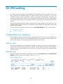
SSL VPN auditing ·······················································································································································93
Comprehensive analysis················································································································································ 93
Online users ··························································································································································· 93
Online users trends················································································································································ 94
Daily user statistics ················································································································································ 94
Device monitoring ················································································································································· 95
SSL VPN log auditing ···················································································································································· 96
User access records auditing ······························································································································· 96
Operation log auditing ········································································································································· 96
Resource access auditing ····································································································································· 97
Authentication failure auditing····························································································································· 97
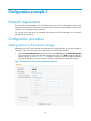
Configuration example 1 ··········································································································································99
Network requirements ··················································································································································· 99
Configuration procedure ··············································································································································· 99
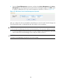
Adding devices to the firewall manager············································································································· 99
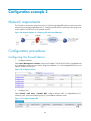
Configuration example 2 ······································································································································· 101
Network requirements ·················································································································································101
Configuration procedures ···········································································································································101
Configuring the firewall device··························································································································101
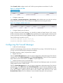
Configuring the Firewall Manager ····················································································································102
Configuring intrusion detection in firewall and sending logs to Firewall Manager·····································103
Verification····································································································································································107
Firewall logs and Firewall Manager analysis ··································································································107
Support and other resources ·································································································································· 111
Contacting HP ······························································································································································111
Subscription service ············································································································································111
Related information······················································································································································111
Documents ····························································································································································111
Websites·······························································································································································111
Conventions ··································································································································································112
Index ········································································································································································ 114
ii
Overview
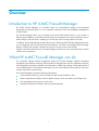
Introduction to HP A-IMC Firewall Manager
HP A-IMC Firewall Manager is a powerful system for comprehensive analysis and centralized
management of firewall devices. It is an important component of the HP A-Intelligent Management
Center (A-IMC).
The Firewall Manager allows you to manage and control all HP firewall devices in your network. It
features great scalability, visual realtime event monitoring, comprehensive security event analysis such as
attack analysis, and rich reports, enabling you to learn the network security status at any time.
In addition, the Firewall Manager provides the Security Socket Layer (SSL) VPN log auditing function for
you to analyze SSL VPN users and monitor firewall devices. SSL VPN is an emerging VPN technology
based on HTTPS, and provides a measure of security for remote access to the intranet.
Together with HP firewall devices, the Firewall Manager provides you with visual, all-around, powerful
network security protection.
What HP A-IMC Firewall Manager can do
As a powerful, efficient firewall management system, the Firewall Manager supports centralized
management and realtime monitoring of firewall devices throughout the network, implements collection
and comprehensive analysis of attack event information, enables log auditing, and provides kinds of
visual, detailed reports. From the all-around reports, you can see the history security status as well as the
security trends of the network easily.
The Firewall Manager presents the following key features:
•
Visual realtime monitoring, which can help you detect network attacks in time.
•
Perfect comprehensive analysis and rich statistics reports, which can reduce your analysis time.
•
Fine log auditing, allowing you to track events.
•
Friendly and easy-to-use interface, allowing easy deployment.
1
Installation and uninstallation
Installing the firewall manager
The software and hardware requirements of the Firewall Manager are as follows:
•
Hardware: P4 2.0 CPU or above, 1.5G memory or more, 80G disk or more.
•
Operating system: Windows 2003 Server (recommended) or Windows XP, installed with the
up-to-date patches.
•
Browser: IE 6.0 or above
To install HP A-IMC Firewall Manager, you only need to run the executable file install.exe, which is under
the installation directory, and click Next repeatedly as prompted.
CAUTION:
After finishing installation, you must restart the operating system.
Registering the firewall manager
In the address bar of the browser, enter http://localhost/ to open the login page. The default login
username and password are admin and admin1 respectively.
CAUTION:
The last character of the password is digit 1.
When you log in to the Firewall Manager for the first time, you will see the license information page and
such a prompt: You haven’t registered. Please register to use the system normally. You can obtain a
formal license, and register your license by following this procedure:
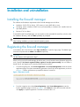
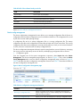
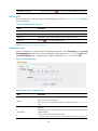
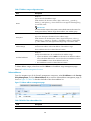
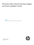
1.
From the navigation tree, select License Application under License Management to enter the license
application page. The system automatically generates a host ID for license application, as shown
in Figure 1. Perform operations as prompted to obtain a license file.
Figure 1 Generate a host ID
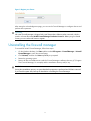
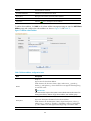
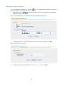
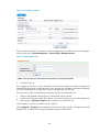
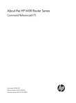
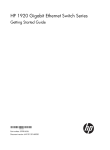
2.
From the navigation tree, select License Registration under License Management to enter the
license registration page, as shown in Figure 2. Click Browse to select the license file and then
click Apply to complete registration. The suffix of a license file is lic.
2
Figure 2 Register your license
After seeing the acknowledgement page, you can use the Firewall Manager to configure devices and
perform other operations.
CAUTION:
HP A-IMC Firewall Manager is shipped with a trial license that is effective within one month, which is
saved in a license file named A-IMC Firewall Manager Evaluation License.lic. Before you get a formal
license, you can use the trial license to register.
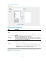
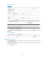
Uninstalling the firewall manager
To uninstall HP A-IMC Firewall Manager, follow these steps:
1.
On the Windows desktop, click Start and then select All Programs > Firewall Manager > Uninstall
Firewall Manager to enter the uninstall page.
2.
Click Uninstall, and then click Next repeatedly as prompted.
3.
Restart the operating system.
4.
Remove all files and subdirectories under the Firewall Manager installation directory (C:\Program
Files\Firewall Manager, for example) and the installation directory itself, if any.
CAUTION:
During the uninstallation process, no system data backup operation is performed and all data is removed.
If you need the system data, backup the data before uninstalling the Firewall Manager.
3
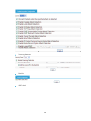
System management
The system management component is mainly used to configure the firewall devices to be managed by
the Firewall Manager.
To access the system management component, select the System Management tab. Then, you can
perform:
•
Device management
•
Operator management
•
System configuration
•
License management
The license management function allows you to apply for, register, and view a license. The license
mechanism is used for enterprise identity authentication.
Device management
The device management module allows you to perform the following tasks:
•
Managing devices
•
Managing batch import
•
Managing device groups
•
Managing events
•
Managing device access templates
•
Managing the device software database
•
Managing deployment tasks
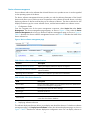
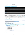
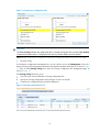
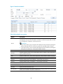
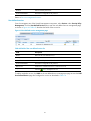
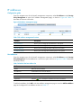
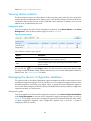
Managing devices
Device management
After completing device group and template configuration, you can add devices to be managed. Only
after you add devices to the system component successfully, can you add the devices to the firewall
component to collect statistics on and analyze attack information. The device management page allows
you to add and delete devices. The device list shows the details of all managed devices, and provides the
links for you to export configurations and connect to the devices through web or Telnet.
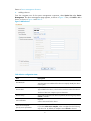
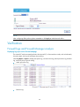
1.
Configuration guide
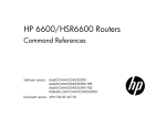
From the navigation tree of the system management component, select Device List under Device
Management. The device management page appears, showing the basic information of all devices
added successfully to the Firewall Manager.
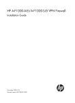
4
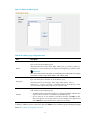
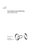
Figure 3 Device management page
Table 1 Device management functions
Function
Description
Device list
Allows you to view details about devices, export configurations, and
connect to the devices through web or Telnet.
Adding a device
Allows you to add devices to be managed.
Allows you to delete devices from the list of managed devices.
Deleting devices
Follow these steps:
1. Select the check boxes before the devices to be deleted.
2. Click Delete.
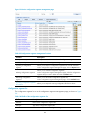
Refreshing device information
2.
Allows you to obtain the up-to-date device information.
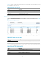
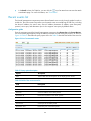
Device list
From the navigation tree of the system management component, select Device List under Device
Management. The device management page appears, as shown in Figure 3. Table 3 describes the fields
of the device list.
Table 2 Device query option
Option
Description
Device Group
Select a device group to list all devices in the device group.
Table 3 Fields of the device list
Field
Description
Running Status
Status of the device. You can click the link to view the event list of the
device. For more information, see “Managing events.”
Device Label
Name and IP address of the device. You can click the link to view the
details of the device and modify the relevant information. For more
information, see “Device information.”
Device Group
Device group to which the device belongs
Device Model
Model of the device
IP Address
IP address of the device
Operation
• Click the
• Click the
5
icon of a device to open the web console for the device.
icon of a device to telnet to the device.
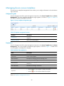
Return to Device management functions.
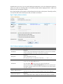
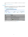
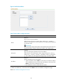
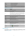
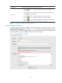
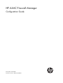
3.
Adding a device
From the navigation tree of the system management component, select Device List under Device
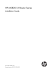
Management. The device management page appears, as shown in Figure 3. Then, click Add to add a
device, as shown in Figure 4 and Table 4.
Figure 4 Add a device
Table 4 Device configuration items
Item
Description
Required
Host Name/IP
Type the name or IP address of the device to uniquely identify the device
in the system.
Required
Device Label
Type a label for the device, which can be used as an alias of the device.
The device label can comprise up to 20 characters.
Device Group
Time Calibration
Select access template
Specify access parameters
Select a device group for the device. By default, the device group named
default is selected.
Required
Select a time mode for the device.
Required. Select either of them.
If you select Select access template, select a template from the following
drop-down list. By default, the template named default is selected.
6
If you select Specify access parameters, specify the access parameters,
including Web Username, Web Password, Web Port, Telnet Username,
Telnet Password, SNMP Version, Community String for Reading, and
Community String for Writing.
Required
Web Username
Specify the username for managing the device through web.
The username can comprise up to 20 characters.
Required
Web Password
Specify the password for managing the device through web.
The strength of the password must meet the password strength
requirements of the device.
Optional
Web Port
Specify the port of the device to be connected with the network.
The port number must be an integer in the range from 0 to 65535.
Optional
Telnet Username
Specify the username for telneting to the device.
The username can comprise up to 20 characters.
Optional
Specify the password for telneting to the device.
Telnet Password
IMPORTANT:
The strength of the password must meet the password strength requirements
of the device.
SNMP Version
Required
Select an SNMP version, which can be SNMPv1, SNMPv2, or SNMPv3.
Required
Community String for Reading
Specify the SNMP read community string to be used for communication
with the device.
The string can comprise up to 20 characters.
Required
Community String for Writing
Specify the SNMP write community string to be used for communication
with the device.
The string can comprise up to 20 characters.
Required for SNMPv3
Authentication Username
Specify the authentication username to be used for communication with
the device.
Required for SNMPv3
Authentication Protocol
Specify the authentication protocol to be used for communication with the
device.
7
Password
Encryption Protocol
Required when you select the authentication protocol HMAC-MD5 or
SMAC-SHA.
Specify the authentication password to be used for communication with
the device.
Required when you select the authentication protocol HMAC-MD5 or
SMAC-SHA.
Specify the encryption protocol to be used for communication with the
device.
Required when you select the encryption protocol CBS-DES or AES-128.
Password
Specify the encryption password to be used for communication with the
device.
Optional
Configure the cards in the device.
Multi-Card Device
IMPORTANT:
• You can specify the card 1 IP address, card 2 IP address, or both.
• The input IP address must be in the dotted decimal notation, such as
192.168.0.35.
Return to Device management functions.
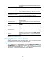
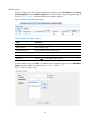
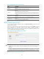
4.
Device information
From the navigation tree of the system management component, select Device List under Device
Management. The device management page appears, as shown in Figure 3. Then, you can click the
device label link of a device to display the details of the device and modify the information of the device,
as shown in Figure 5.
Figure 5 Device information
8
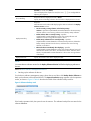
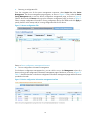
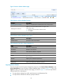
Device software management
Device software refers to the software that a firewall device runs to provide services. It can be regarded
as the operating system of the device.
The device software management function provides you with the software information of the firewall
devices and allows you to perform a series of operations to the software of firewall devices, including
deploying software to devices and backing up the software of devices. The device software list also
displays the device type, the current software version, and the latest available new software version.
1.
Configuration Guide
From the navigation tree of the system management component, select Device List under Device
Management. The device management page appears, as shown in Figure 3. Then, select the Device
Software Management tab to bring up the device software management page, as shown in Figure 6.
Table 5 describes the device software management functions and Table 6 describes the fields of the
device software list.
Figure 6 Device software management page
Table 5 Device software management functions
Function
Description
Deploying software to devices
Allows you to deploy software to devices as required.
Backing up the software of devices
Allows you to backup the software of selected devices to the device
software database.
Refreshing device information
Allows you to obtain the up-to-date device information.
Table 6 Fields of the device software list
Field
Description
Device Label
Device name and IP address. You can click the link to view details about
the device and modify the configuration.
Device Group
Device group to which the device belongs
Device Type
Model of the device
Current Version
Current software version of the device
Latest Version
Latest software version available for the device. This version information
comes from the software database.
2.
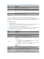
Deploying software to devices
This software deployment function allows you to deploy main boot file to devices. On the device software
management page, click Deploy Device Software to enter the software deployment page, as shown in
Figure 7. Table 7 describes the software deployment configuration items. You can deploy software to
9
multiple devices at a time. You can specify deployment parameters, such as the deployment sequence,
policy, time, and error handling mode. A successfully created software deployment task is listed in the
deployment task management module.
How many boot files can be stored on a device depends on the device's disk space. Generally, two files,
one main boot file and one backup boot file, are stored on the device.
Figure 7 Deploy software to devices
Table 7 Software deployment configuration items
Item
Description
Required
Task Name
Type the name of the deployment task. By default, it consists of the word Task,
a string indicating the current time, and a space in between.
Required
Description
Type a description for the task.
The description must not contain these characters: ' " < > & % : ; / \
Click this button to add a device to which you want to deploy a software
version. You can add multiple devices.
Add Device
Deploy Software Version
Deployment Sequence
You can click the
icon of a device to remove it from the list.
Select a location from the Device Storage Path drop-down list to specify where
the software should be saved on the device. Generally, the root directory of the
CF card is selected.
Required
Click the link in this column to select the software version to be deployed.
Required
Select a deployment mode to deploy the software to the devices in parallel
10
(Parallel) or one by one (Serial).
When the deployment sequence is serial, the icons
adjusting the sequence.
Error Handling
are configurable for
Required when the deployment mode is Serial.
Specify the error handling scheme to be used when a deployment error occurs.
Required
Select the actions to be taken after deploying the software selected in the Deploy
Software Version column.
• Set the currently running software as the backup startup
software—Specifies secpath1000fe-cmw520-b5002.bin as the main startup
software and the current running software as the backup startup software.
• Delete software that is currently running—Specifies
Deployment Policy
secpath1000fe-cmw520-b5002.bin as the main startup software and
deletes the current running software from the device.
• Delete startup software that is currently backup—Specifies
secpath1000fe-cmw520-b5002.bin as the main startup software, deletes the
backup startup software from the device, and leaves the current running
software on the device.
• Reboot the device immediately after deploying—Specifies
secpath1000fe-cmw520-b5002.bin as the main startup software, leaves all
software files stored on the device, and reboots the device. After the device
reboots, secpath1000fe-cmw520-b5002.bin is the current running software
of the device.
Deployment Time
Specify the execution time of the deployment task.
NOTE:
You must select a software version for the Deploy Software Version field before deploying software to
devices.
Return to Device software management functions.
3.
Backing up the software of devices
On the device software management page, select devices and then click Backup Device Software to
back up the software of the selected devices. The Import from Device page appears with the operation
results, as shown in Figure 8. Table 8 describes the fields of the software backup result list.
Figure 8 Software backup result
If the backup operation fails, the system shows the reasons. The software backup files are stored in the
software database.
11
Table 8 Fields of the software backup result list
Field
Description
Device Label
Device name and IP address
Software Name
Name of the software backed up
Size
Size of the backup file for the software
Start Time
Start time of the backup operation
Status
Result of the backup operation
Result
Description of the operation result or failure reason
Return to Device software management functions.
Device config management
The device configuration management function allows you to manage configuration files of devices. A
configuration file records the configurations users have made on the device. The configuration file is used
by the device to filter traffic passing through.
A configuration file can be a startup configuration file or a running configuration file. The startup
configuration file refers to the configuration file that a device keeps and will use at next boot. The running
configuration file refers to the configuration currently used by a device, which you can save to the device
as a file, and once saved, becomes the startup configuration file.
The device configuration management function supports setting baseline versions for devices, managing
the running versions and startup versions of devices, and deploying configuration files to devices.
1.
Configuration guide
From the navigation tree of the system management component, select Device List under Device
Management. The device management page appears, as shown in Figure 3. Then, select the Device
Config Management tab to enter the device configuration management page, as shown in Figure 9.
Table 9 describes the device configuration management functions and Table 10 describes the fields of
the device configuration management list.
Figure 9 Device configuration management page
Table 9 Device configuration management functions
Function
Description
Backing up configuration files
Allows you to back up the running configuration file and/or the
startup configuration file of a device. Backup files are identified by
labels and version numbers.
Restoring a configuration file
Allows you to restore the startup and/or backup configuration file of
12
a device to another version.
Synchronizing configurations
Allows you to deploy new configuration settings to devices to make
them take effect.
Restarting devices
Allows you to restart devices.
Table 10 Fields of the device configuration management list
Field
Description
Device Label
Device name and IP address. You can click the link to view details about the device
and modify the configuration.
Device Group
Device group to which the device belongs
Last Backup Time
Time of the last configuration file backup operation
Check whether the current configuration of the device is consistent with that last
backed up.
Last Operate Time
2.
Time of the last configuration file operation
Backing up configuration files
From the navigation tree of the system management component, select Device List under Device
Management. The device management page appears, as shown in Figure 3. Then, select the Device
Config Management tab to enter the device configuration management page. Select a device by
selecting the check box and click Backup to bring up the backup configuration page, as shown in Figure
10. A backup file is uniquely identified by a version number that is assigned by the system. After a file is
icon in the Management column of a device to view the detailed information of
backed up, click the
the backup configuration files.
Figure 10 Backup configuration files
Return to Device configuration management functions.
13
3.
Restoring a configuration file
From the navigation tree of the system management component, select Device List under Device
Management. The device management page appears, as shown in Figure 3. Then, select the Device
Config Management tab to enter the device configuration management page, as shown in Figure 9.
Select a device and click Restore to bring up the restoration configuration page, as shown in Figure 11.
Select a startup configuration file and/or running configuration file by their labels and click Apply to
specify the files as the startup and/or running configuration files for the device.
Figure 11 Restore configuration files
Return to Device configuration management functions.
4.
Device configuration information management
On the device configuration management list, you can click the icon in the Management column of a
device to bring up the configuration information management page of the device, as shown in Figure 12.
Table 11 describes the tabs on the device configuration information management page and the functions
provided on the tabs.
Figure 12 Device configuration information management interface
14
Table 11 Tabs on the device configuration information management page and functions provided
Tab
Description
Label
A label represents a configuration file of a device. .
Running Config
Allows you to perform operations on running configuration files of different versions.
Startup Config
Allows you to view, back up, and delete the current startup configuration file of a
device.
The functions are the similar to those for management of running configuration files.
Draft
5.
Allows you to manage drafts for a device.
Label
A label is used to indicate the backup running and/or startup configuration files of a device.
On the device configuration management list, you can click the icon in the Management column of a
device to bring up the configuration information management interface of the device, as shown in Figure
12.
The Label tab allows you to:
•
Add and delete labels.
•
View the information of the backup configuration file, such as version number and backup time. A
backup file is uniquely identified by a version number assigned by the system.
•
Compare two configuration files to find the differences.
•
Click the restoration icon to set the startup configuration file and/or running configuration file of a
label as the startup configuration file and/or running configuration file for the device.
Table 12 Fields of the configuration label list
Field
Description
Label
Label of a startup configuration file and/or running configuration file.
Running Config
Version number of the running configuration file associated with the label.
Backup Time
Time when the running configuration file is backed up.
Allows you to compare two configuration files including the drafts to find the
differences.
Follow these steps:
Compare
3. Click the
icon of a file and select Compare as Left from the menu to place the
file on the left side of the comparison page.
4. Click the
icon of another file and select
Compare To to place the file on
the right side of the comparison page, as shown in Figure 13.
IMPORTANT:
The running configuration file does not support the xml format.
Startup Config
Version number of the startup configuration file associated with the label.
Backup Time
Time when the startup configuration file is backed up.
Restore
Allows you to set the configuration file(s) identified by the label as the startup
configuration file and/or running configuration file for the device.
15
Figure 13 Compare two configuration files
CAUTION:
The label Currently indicates the configuration file is currently used by the device and the label Baseline
indicates the baseline version. Configuration files with any of these labels cannot be deleted.
Return to Tabs on the device configuration information management page and functions provided.
6.
Running Config
On the device configuration management list, you can click the icon in the Management column of a
device to bring up the configuration information management interface of the device, as shown in Figure
12. Then, click the Running Config tab to enter the running configuration file management page, as
shown in Figure 14.
The Running Config tab allows you to:
•
View, back up, restore and delete a running configuration file.
•
Specify the running configuration as the baseline or save it as a draft.
•
Compare two configuration files to find the differences.
Figure 14 Running configuration file list
16
Table 13 Fields of the running configuration list
Field
Description
Version
Uniquely identifies the running configuration file. The version number is assigned
automatically by the system for each backup file.
Backup Time
Time when the running configuration file is backed up.
Label
Label for this version.
Compare
Allows you to compare two configuration files including the drafts to find the
differences.
Set Baseline
Allows you to set the running configuration file as the baseline.
Label Management
Allows you to re-label the running configuration file.
Save as Draft
Allows you to save the running configuration file as a draft, and then edit the
content of the draft.
Restore
Allows you to set the configuration file identified by the version as the running
configuration file for the device.
Return to Tabs on the device configuration information management page and functions provided.
7.
Draft
You can save a configuration file as a draft, or create a new draft.
On the device configuration management list, you can click the icon in the Management column of a
device to bring up the configuration information management interface of the device, as shown in Figure
12. Then, click the Draft tab to enter the draft management page, as shown in Figure 15. You can
customize a configuration file and apply it to the device.
The Draft tab allows you to:
•
Edit a configuration file and save it as a draft.
•
Add and delete drafts.
•
Click the restoration icon to replace the contents of the draft with the current startup or running
configuration file.
•
Compare a draft with itself, another draft, or any configuration file to find the differences.
Figure 15 Draft list
Table 14 Fields of the draft list
Field
Description
Name
Name of the draft.
17
Description
Remarks on the draft.
Creation Time
Time when the draft is created.
Last Modify Time
Last time when the draft is modified.
Compare
Allows you to compare the draft with a configuration file to find the differences.
Allows you to set the draft as the configuration file for the device.
Restore
IMPORTANT:
Do not set a draft as the startup configuration file.
Return to Tabs on the device configuration information management page and functions provided.
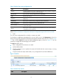
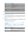
Managing batch import
The batch import function allows you to add devices to the A-IMC Firewall Manager in batches by using
a batch import file.
Configuration guide
From the navigation tree of the system management component, select Batch Import under Device
Management. The batch import page appears, as shown in Figure 16. Click Browse to select the batch
import file, and then click Apply.
Figure 16 Batch import of devices
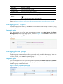
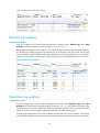
Managing device groups
The device group management function allows you to add, modify, and delete device groups. When you
add devices later, you can group devices into device groups so that you can manage and collect statistics
on users, devices, and IP addresses by device group.
Configuration guide
From the navigation tree of the system management component, select Device Group List under Device
Management. The device group management page appears, as shown in Figure 17. Table 15 describes
the device group management functions.
Figure 17 Device group management page
18
Table 15 Device group management functions
Function
Description
Device group list
Allows you to view details about device groups and modify and delete
device groups.
Adding a device group
Allows you to add a device group and configure the device group name
and description.
Device group list
From the navigation tree of the system management component, select Device Group List under Device
Management. The device group management page appears, as shown in Figure 17. Details of all device
groups are displayed on the page.
Table 16 Fields of the device group list
Field
Description
Device Group Name
Name of the device group
Description
Description of the device group
Operation
• Click the
icon of a device group to modify the device group.
• Click the
icon of a device group to delete the device group.
Return to Device group management functions.
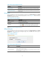
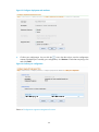
Adding a device group
From the navigation tree of the system management component, select Device Group List under Device
Management to enter the device group management page. Then, click Add to add a device group as
shown in Figure 18 and Table 17.
Figure 18 Add a device group
Table 17 Device group configuration items
Item
Description
Required
Device Group Name
Type a name for the device group.
The device group name can comprise up to 40 characters and must not contain
these characters: ” < > ’ & % : ; / \
19
Optional
Description
Type a description for the device group.
The description can comprise up to 40 characters.
Return to Device group management functions.
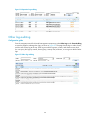
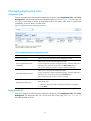
Managing events
Configuration guide
The event management function records the operations on managed devices and logs the events,
allowing you to track the status of devices.
From the navigation tree of the system management component, select Events under Device Management.
The device event list page appears by default, as shown in Figure 19.
Table 18 describes the device management functions.
Figure 19 Device event list page
Table 18 Event management functions
Function
Description
Device event list
Allows you to view details about device events.
Device interface event list
Allows you to view details about device interface events.
Device event list
Table 19 describes the device event query options. You can use any combination of the options to query
for the device events of interest.
Table 19 Device event query options
Option
Time
Device IP
Description
Select the time period during which the device events occurred.
By default, the value of this option is --, which means any time.
Type the IP address of the device, in dotted decimal notation.
Select the severity level of the device events.
Severity
Severity levels in descending order are critical, major, minor, and
warning. By default, the value of this option is --, which means all levels.
20
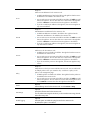
Table 20 describes the fields of the device event list. You can select the check boxes before events and
then click Delete to delete the events.
Table 20 Fields of the device event list
Field
Description
Severity
Severity level of the device event
Source
Label and IP address of the device that is the source of the device event
Description
Description of the device event
Time
Time when the device event occurred
Device interface event list
Select the Device Interface Event List tab to enter the device interface event list page, as shown in Figure
20.
Figure 20 Device interface event list
Table 21 describes the event query options. You can use any combination of the options to query for the
events of interest.
Table 21 Device interface event query options
Option
Start Time
End Time
Description
Select the time period during which the device interface events occurred.
Table 22 describes the fields of the device interface event list. You can select the check boxes before
events and then click Delete to delete the events.
Table 22 Fields of the device interface event list
Field
Description
Time
Time when the device interface event occurred
Device IP
IP address of the device in the device interface event
Interface
Interface in the device interface event
Status
Status of the device interface event
21
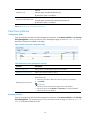
Managing device access templates
The device access template management function allows you to configure information such as the device
login password.
Configuration guide
From the navigation tree of the system management component, select Access Template List under Device
Management. The access template management page appears, as shown in Figure 21. Table 23
describes the template management functions.
Figure 21 Access template management page
Table 23 Template management functions
Function
Description
Template list
Allows you to view details about access templates and modify and delete
templates.
Adding a template
Allows you to add templates.
Template list
From the navigation tree of the system management component, select Access Template List under Device
Management. The access template management page appears, as shown in Figure 21. Details of all
access templates are displayed on the page.
Table 24 Fields of the template list
Field
Description
Template
Name of the template
Version No.
Version of the template
Web Username
Username for managing the device through web
Web Port
Port of the device providing web access service
Web Password
Password for managing the device through web, displayed as a string of
asterisks (*)
Telnet Username
Username for telneting to the device
Telnet Password
Password for telneting to the device, displayed as a string of asterisks (*)
Operation
• Click the
icon of a template to modify the template.
• Click the
icon of a template to delete the template.
Return to Template management functions.
22
Adding a template
From the navigation tree of the system management component, select Access Template List under Device
Management to enter the access template management page. Then, click Add to add a template as
shown in Figure 22 and Table 25.
Figure 22 Add a template
Table 25 Template configuration items
Item
Template Name
Description
Required
Type a name for the template, a string of 1 to 20 characters.
Required
Web Username
Specify the username for managing the device through web.
The username can comprise up to 20 characters.
Required
Specify the password for managing the device through web.
Web Password
IMPORTANT:
The strength of the password must meet the password strength requirements
of the device.
Required
Web Port
Specify the port of the device providing web access service.
Port 80 is the default.
Optional
Telnet Username
Specify the username for telneting to the device.
The username can comprise up to 20 characters.
Optional
Telnet Password
Specify the password for telneting to the device.
IMPORTANT:
23
The strength of the password must meet the password strength requirements
of the device.
SNMP Version
Required
Select an SNMP version, which can be SNMPv1, SNMPv2, or SNMPv3.
Required
Community String for Reading
Specify the SNMP read community string to be used for communication
with the device. It can be a string of up to 20 characters.
Required
Community String for Writing
Specify the SNMP write community string to be used for communication
with the device. It can be a string of up to 20 characters.
Required for SNMPv3
Authentication Username
Specify the authentication username to be used for communication with
the device.
Required for SNMPv3
Authentication Protocol
Password
Encryption Protocol
Specify the authentication protocol to be used for communication with the
device.
Required when you select the authentication protocol HMAC-MD5 or
SMAC-SHA.
Specify the authentication password to be used for communication with
the device.
Required when you select the authentication protocol HMAC-MD5 or
SMAC-SHA.
Specify the encryption protocol to be used for communication with the
device.
Required when you select the encryption protocol CBS-DES or AES-128.
Password
Specify the encryption password to be used for communication with the
device.
Return to Template management functions.
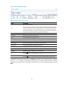
Managing the device software database
The device software database is used to save all device software. It allows you to import device software
to the database from files or devices, and deploy software to devices.
Configuration guide
From the navigation tree of the system management component, select Device Software Database under
Device Management to enter the device software database page, as shown in Figure 23. Table 26
describes the device software database functions, Table 27 describe the device software database query
option, and Table 28 describes the fields of the device software database list.
24
Figure 23 Device software database page
Table 26 Device software database functions
Function
Description
Importing device software
Allows you to import device software from a file or from a device.
Allows you to remove software that is no longer in use.
Deleting device software
Follow these steps:
1. Select the check box before software names.
2. Click Delete.
Deploying software to device
Allows you to deploy software to devices.
Table 27 Device software database query option
Option
Description
Software Name
Specify the name of the software.
Table 28 Fields of the device software database list
Field
Description
Software Name
Name of the software file
Declaration
Remarks on the software
Import Time
Time when the software is imported
Size
Size of the software file
Check
Allows you to check whether the exported software is consistent with the
device software.
Rename
Allows you to rename the software file.
Export
Allows you to export the software to a local place
Deployment
Allows you to deploy the software to devices.
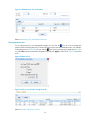
Importing device software
From the navigation tree of the system management component, select Device Software Database under
Device Management to enter the device software database page, as shown in Figure 23. Then, click
Import to bring up the device software import page, as shown in Figure 24. You can import device
software from a file or from devices:
•
To import device software from a file, specify the source and destination files.
•
To import device software from devices, specify the devices.
25
Figure 24 Device software import page
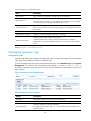
Managing deployment tasks
This function allows you to view all deployment task information.
Configuration guide
From the navigation tree of the system management component, select Deploy Task under Device
Management to enter the deployment task list page, as shown in Figure 25.
Figure 25 Deployment task list
On the deployment task list, you can:
•
Execute deployment tasks immediately.
•
Cancel deployment tasks.
•
Delete deployment tasks.
•
Refresh the deployment task information.
Table 29 describes the deployment task query option and Table 30 describes the fields of the
deployment task list.
Table 29 Deployment task query option
Option
Description
Task Status
Select a state to list all deployment tasks in the state.
Table 30 Fields of the deployment task list
Field
Description
Execution Status
Current status of the deployment task
Task Name
Name of the deployment task
Task Type
Type of the deployment task
26
Creation Time
Time when the deployment task is created
Creator
Creator of the deployment task
Start Time
Time when the deployment task starts
End Time
Time when the deployment task ends
Copy
Allows you to create a deployment task based on the selected one.
Operator management
The operator management function allows you to manage operators and operation logs, and to change
operator passwords.
Managing operators
This function allows you to manage the rights of web users. There are three user levels: common operator,
system administrator, and super administrator. A higher level operator has all the rights of operators of
a lower level. Table 31 describes the rights of the three user levels.
Table 31 User levels and the rights
User level
Rights
Common operator
• Use the Ping tool
• Cannot perform any configuration
(visitor level)
System administrator
(monitoring level)
Super administrator
(management level)
•
•
•
•
Use the Ping tool
View configuration information except for user information
View log information except for operation logs
Perform configurations except for user configuration, operation logging
configuration,managing device groups, batch import, access template
management,System Parameter,Management Ports,Mail server,LDAP Server
Management,Log Retention Time,disk monitoring,subsystem
management,license management
• View all configurations
• View all logs
• Perform all configurations
Configuration guide
From the navigation tree of the system management component, select Operators under Operator
Management. The operator management page appears, as shown in Figure 26.
Figure 26 Operator management page
27
Table 32 Operator management functions
Function
Description
Operator list
Allows you to view details about operators, modify operator information,
and delete operators.
Adding an operator
Allows you to add operators.
Operator list
From the navigation tree of the system management component, select Operators under Operator
Management. The operator management page appears, as shown in Figure 26.
Table 33 Fields of the operator list
Field
Description
Login Name
Username used by the operator at login
Role
Operation level of the operator
Last Login Time
Last time when the operator logged in
Managed Device Groups
Device groups for which the operator has operation rights
Authentication Mode
Authentication mode of the operator
Operation
• Click the
icon of an operator to modify the operator’s information.
• Click the
icon of an operator to delete the operator.
Return to Operator management functions.
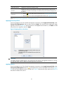
Adding an operator
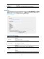
From the navigation tree of the system management component, select Operators under Operator
Management to enter the operator management page. Then, click Add to enter the page for adding an
operator, as shown in Figure 27. Table 34 describes the operator configuration items.
Figure 27 Add an operator
28
Table 34 Operator configuration items
Item
Description
Login Name
Type a name for the operator, a string of up to 40 characters.
Specify a password for the operator to use at login.
Login Password
The password must comprise 6 to 20 alphanumeric characters, and its strength
must meet the password strength requirements of the device.
Confirm Password
Type the password again, which must be the same as that for Login Password. If
the two are not the same, an error message will appear, telling you that they must
be identical.
Role
Select an operation level for the operator.
Manage Device Group
Specify which device groups the operator can manage.
Select an authentication mode for the operator.
Authentication Mode
Available authentication modes include local authentication and LDAP
authentication. If you select LDAP authentication, you must also select an LDAP
server.
Return to Operator management functions.
Managing operation logs
Configuration guide
Operation logs reflect what operators have done after login. A super administrator can view operations
logs, query logs by different conditions, and delete logs.
From the navigation tree of the system management component, select Operation Logs under Operator
Management. The operation log management page appears, as shown in Figure 28. Table 35
describes the operation log query options. You can use any combination of the options to query for the
logs of interest.
Figure 28 Operation log management page
Table 35 Operation log query options
Option
Description
Operator
Specify the operator whose logs you are interested in.
Gateway IP
Type the IP address of the gateway.
Select the operation result of the operations.
Operation Result
By default, the value of this option is --, which means both the succeeded and
failed operations.
29
Table 36 Fields of the operation log list
Field
Description
Operator
Name of the operator
IP Address
IP address of the PC used by the operator to log in
Time
Time when the operation occurred
Operation
What the operator did
Result
Whether the operation succeeded or failed
Details
Operation details
Changing your login password
This function allows you to change your login password.
From the navigation tree of the system management component, select Password under Operator
Management to enter the page for changing your login password, as shown in Figure 29. Table 37
describes the configuration items for changing your password.
Figure 29 Change your login password
Table 37 Configuration items for changing your password
Item
Description
Required
Old Password
Type the current password.
The password must be an alphanumeric string of 6 to 20 characters.
Required
New Password
Type the new password.
The password must be an alphanumeric string of 6 to 20 characters.
Required
Confirm Password
Type the new password again.
This password must be exactly the same as that for New Password.
30
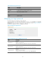
System configuration
Configuring system parameter
Configure the system parameter to allow non-SNMP devices in the system.
Configuration guide
From the navigation tree of the system management component, select System Parameter under System
Config. The system parameter configuration page appears, as shown in Figure 30. Select the check box
for the parameter and click Apply.
Figure 30 System parameter setting
Configuring management ports
This module allows you to specify the Firewall Manager background ports for receiving various logs from
devices.
Configuration guide
From the navigation tree of the system management component, select Management Ports under System
Config. The management ports configuration page appears, as shown in Figure 31. Table 38 describes
the management port configuration items.
Figure 31 Management port configuration page
Table 38 Management port configuration items
Item
Description
NAT Logs Port
Required
31
Type the port for receiving NAT logs.
The port number must be in the range from 1 to 65534.
Required
Syslog Port
Type the port for receiving syslogs.
The port number must be in the range from 1 to 65534.
Required
NetStream V9 Logs Port
Type the port for receiving NetStream V9 logs.
The port number must be in the range from 1 to 65534.
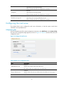
Configuring the mail server
This module allows you to configure the mail server information, so that the system emails alarm
information to the specified server.
Configuration guide
From the navigation tree of the system management component, select Mail Server under System Config.
The mail server configuration page appears, as shown in Figure 32. Table 39 describes the mail server
configuration items.
Figure 32 Configure the mail server
Table 39 Mail server configuration items
Item
Description
Required
SMTP Mail Server IP
Type the IP or domain name of the mail server.
The domain name can comprise up to 100 characters.
Optional
Require authentication
Specify whether the mail server authenticates the identities of users trying to
access.
Username
Optional
32
Type the username for identity authentication on the mail server.
The password can comprise up to 80 characters.
Password
Sender’s Mail Address
Optional
Type the password for identity authentication on the mail server.
Required
Type the mail address of the sender.
Managing filters
A filter is used to filter the information of IPS devices to present only information that you are interested in
through reports.
By configuring filters, you can specify filtering conditions flexibly.
Configuration guide
From the navigation tree of the system management component, select Filter Management under System
Config. The filter management page appears, as shown in Figure 33. Table 40 describes the filter
management functions.
Figure 33 Filter management page
Table 40 Filter management functions
Function
Description
Filter list
Allows you to view details about filters and modify filter settings.
Adding a filter
Allows you to add a filter.
Allows you to delete filters that are no longer in use.
Deleting filters
Follow these steps:
1. Select the check boxes before the filters to be deleted.
2. Click Delete.
Filter list
From the navigation tree of the system management component, select Filter Management under System
Config. The filter management page appears, as shown in Figure 33.
Table 41 Fields of the filter list
Field
Description
Filter Name
Name of the filter
Filter Description
Description of the filter
Device
Device that the system collects statistics on
33
Field
Description
Operation
Click the
icon of a filter to modify the settings of the filter.
Return to Filter management functions.
Adding a filter
From the navigation tree of the system management component, select Filter Management under System
Config to enter the filter management page. Then, click Add to enter the page for adding a filter, as
shown in Figure 34. Table 42 describes the filter configuration items.
Figure 34 Add a filter
Table 42 Filter configuration items
Item
Description
Required
Filter Name
Type a name for the filter.
The filter name can comprise up to 40 characters.
Optional
Filter Description
Type a description for the filter.
The description can comprise up to 50 characters.
Device
Source IP
Destination IP
Source Port
Optional
Select the devices that you want the system to collect statistics on.
Optional
Specify the source IP addresses that you want the system to collect statistics on.
Optional
Specify the destination IP addresses that you want the system to collect statistics on.
Optional
34
Specify the source ports that you want the system to collect statistics on.
Destination Port
Protocol
Event
Optional
Specify the destination ports that you want the system to collect statistics on.
Optional
Select the protocols that you want the system to collect statistics on.
Optional
Specify the events that you want the system to collect statistics on.
CAUTION:
The configuration items given in the previous table can be used to define query conditions. For example,
you can enter source IP address 1.1.1.1 to search for data with the source IP address being 1.1.1.1, or
enter source IP address 1.1.1.1 and select the Invert selection check box to search for data whose source
IP address is not 1.1.1.1.
Return to Filter management functions.
Managing LDAP servers
This function allows you to configure LDAP servers. Then, you can select LDAP authentication to verify the
operator’s username and password when they log in to the Firewall Manager system.
Configuration guide
From the navigation tree of the system management component, select LDAP Server Management under
System Config. The LDAP server management page appears, displaying all LDAP servers.
Figure 35 LDAP server management page
Table 43 LDAP server management functions
Function
Description
LDAP server list
Allows you to view details about LDAP servers and modify LDAP server settings.
Adding an LDAP server
Allows you to add an LDAP server.
Deleting LDAP servers
Allows you to delete one or more LDAP servers from the system.
LDAP server list
The LDAP server list is on the LDAP server management page, as shown in Figure 35.
35
Table 44 Fields of the LDAP server list
Field
Description
Server Name
Name of the LDAP server
Server IP Address
IP address of the LDAP server
Server Version
Version information of the LDAP server
Operation
Click the
Import Users
The device does not support importing users.
icon of a LDAP server to modify the settings of the filter.
Return to LDAP server management functions.
Adding an LDAP server
From the navigation tree of the system management component, select LDAP Server Management under
System Config. Click Add to add an LDAP server, as shown in Figure 36 and Table 45.
Figure 36 Add an LDAP server
Table 45 LDAP server configuration items
Item
Server Name
Server Version
Server IP
Server Port
Admin DN
Description
Required
Type a name for the LDAP server.
Required
Select an LDAP server version.
Required
Type an IP address for the LDAP server.
Required
Type a port number for the LDAP server.
Required
Type the administrator DN for the LDAP server.
36
Admin Password
Username Attribute
Base DN
Required
Type the administrator password for the LDAP server.
Required
Type a username attribute for the LDAP server.
Required
Type a base DN for the LDAP server.
Return to LDAP server management functions.
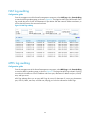
Managing log retention time
This function allows you to configure the period of time during which the system keeps the firewall logs
and SSL VPN logs for query.
Configuration guide
From the navigation tree of the system management component, select Log Retention Time under System
Config. The log retention time configuration page appears, as shown in Figure 37. Set the number of
days that the system keeps the firewall logs and SSL VPN logs and then click Apply.
Figure 37 Log retention time configuration page
Monitoring the disk space
This function provides the usage statistics of the disk space under the system installation directory. It
allows you to set the minimum free disk space, so that an alarm is generated whenever the free disk
space is less than the threshold. You can also specify an email address so that the system sends
generated alarms to the mail box. This function helps reduce data loss due to lack of disk space.
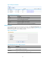
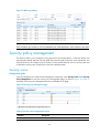
Configuration guide
From the navigation tree of the system management component, select Disk Monitoring under System
Config. The disk space alarm configuration page appears, as shown in Figure 38. On the page, you can
set the disk space alarm threshold, so that the system issues an alarm whenever the free disk space is less
than the threshold.
37
Figure 38 Disk space alarm configuration page
Table 46 Alarm configuration items of the disk space for logs
Item
Description
Required
Warning Disk Space
Set the minimum free disk space required. An alarm is generated once the
actual free disk space is lower than this value.
Optional
Send a report by email
Selecting the check box will make the system send generated alarms to the
specified mail box.
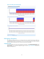
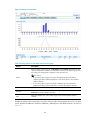
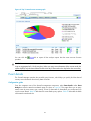
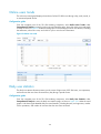
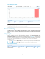
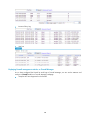
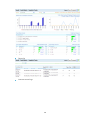
You can also select the Residual Disk Monitoring tab to view the disk space usage information in the last
three hours, 36 hours, and 36 days, and the remaining disk space per day, or select the Detail tab to
view disk space usage statistics of function modules, as shown in Figure 39.
38
Figure 39 Free disk space monitoring page
Managing subsystems
The subsystem management allows you to manage and monitor multiple Firewall Managers effectively.
By adding different systems as the subsystems, you can access these subsystems by simply clicking their
URL links instead of entering the URLs, usernames and passwords repeatedly.
Configuration guide
From the navigation tree of the system management component, select Subsystem Management under
System Config to enter subsystem configuration page, as shown in Figure 40. Table 47 describes the
fields of the subsystem list.
39
Figure 40 Subsystem information
Table 47 Fields of the subsystem list
Field
Description
Server IP
IP address of the server for the subsystem.
Port
Port for connecting to the subsystem.
User Name
Username for logging in to the subsystem.
Password
Password for logging in to the subsystem.
Link
URLs of the subsystem. Click a link to log in to the subsystem.
Adding a subsystem
From the navigation tree of the system management component, select Subsystem Management under
System Config. Click Add to enter the page for adding a subsystem, as shown in Figure 41. Table 48
describes the configuration items for adding a subsystem
Figure 41 Add a subsystem
Table 48 Configuration items for adding a subsystem
Item
Server IP
Server Port
Description
Required
Type the IP address for the subsystem.
Required
Type the port of the subsystem. It defaults to port 80.
40
Required
User Name
Type the username for logging in to the subsystem.
The username can comprise up to 40 characters.
Required
Password
Specify the password for logging in to the subsystem.
The password must comprise 6 to 20 alphanumeric characters,
41
Firewall management
The Firewall Manager enables centralized management of firewall devices in the network, centralized
event collection and analysis, realtime monitoring, event snapshot, comprehensive analysis, event details,
and log auditing. It provides abundant reports, which can be exported periodically.
To access the firewall management component, select the Firewall tab. Then, you can perform:
•
Attack events monitoring
•
Event analysis
•
Event auditing
•
Security policy management
•
Firewall device management
Attack events monitoring
The firewall management component supports centralized monitoring of security events. It can collect
and report attack events in real time, and provide the snapshot information based on firewall devices and
events.
Snapshot of events
The event snapshot presents the attack protection information in the last hour, including the time, total
number of events, blocked events count, source addresses and destination addresses, as well as event
types. Besides, it provides the TopN list of attack events, attack destination IP addresses and ports, attack
sources, and attack protocols, helping you track the latest security status of the network in an intuitive
way.
Configuration guide
From the navigation tree of the firewall management component, select Snapshot of Events under Events
Monitor to enter the event snapshot page, as shown in Figure 42.
42
Figure 42 Snapshot of events
Table 49 Event snapshot query options
Option
Description
Select a device, a device group, or All devices from the Device drop-down list. The
system will display the relevant event information. All devices and device groups that
are under your management will appear in the drop-down list.
Device
IMPORTANT:
• Selecting a device group: Specifies all devices in the device group.
• Selecting a device name: Specifies the single device.
Top
Select a value in the Top drop-down list to specify the number of records to be displayed
in the graphs and lists.
Statistics Time
Period of time during which the statistics were collected. The snapshot statistics time is
the last hour.
Table 50 Fields in the event snapshot lists
Field
Description
Attack Event
Destination IP
Destination Port
Source IP
Attack protection statistics lists, including the event name/destination IP
address/destination port/source IP address/protocol of the attack
Protocol
Event Count
Count of events
Percentage
Percentage of the events
43
•
In the Detail column of a TopN list, you can click the
icon of an attack event to enter the attack
event details page. For more information, see “Event details.”
Recent events list
The firewall management component presents firewall attack events not only through graphs but also in
a table list. The recent events list presents you the attack events occurred during the last hour, including
the device IP address, the event’s time, source IP address, destination IP address, event description,
protocol, source port, and destination port. It also supports events query by different filters.
Configuration guide
From the navigation tree of the firewall management component, select Recent List under Events Monitor.
The recent events page appears, listing the attack events that occurred during the last hour. as shown in
Figure 43. Table 51 describes the query option of the list. Table 52 describes the fields of the event list.
Figure 43 List of recent attack events
Table 51 Query option description
Option
Description
Filter
Select a filter from the drop-down list to display specific events.
Table 52 Fields of the recent events list
Field
Description
Time
Time when the event occurred
Device IP
IP address of the firewall device
Source IP
Source IP address of the attack packets
Destination IP
Destination IP address of the attack packets
Event
Description of the event
Protocol Name
Protocol of the attack packets
Source Port
Source port of the attack packets
Destination Port
Destination port of the attack packets
44
Device monitoring
In addition to the attack event information of the entire network, the firewall management component
also allows you to view the attack event information of every firewall device.
Configuration guide
From the navigation tree of the firewall management component, select Device Monitoring under Events
Monitor to enter the device monitoring page, as shown in Figure 44. The page presents the attack
protection information in the last hour by device, including the total number of events, number of blocked
events, number of source/destination IP addresses, and number of destination ports.
Figure 44 Device monitoring
In the list, you can:
•
icon in the Snapshot column of a firewall device to enter the attack event snapshot
Click the
page of the device. For more information, see “Snapshot of events.”
•
Click the
icon in the Details column of a firewall device to enter the attack event details page of
the device. For more information, see “Event details.”
The firewall management component features comprehensive analysis and statistics reports, through
which you can evaluate the network security status in real time, and take attack prevention measures
accordingly.
Event analysis
Event overview
The system supports comprehensive analysis of attack events, including:
•
Attack event trend analysis during a day, week, month, and a customized period
•
TopN statistics reports by event, destination IP address, source IP address, destination port, and
protocol. You can export the reports.
Configuration guide
From the navigation tree of the firewall management component, select Event Overview under Event
Analysis. The attack event trend page appears by default, as shown in Figure 45. This page allows you
to view attack event trend analysis during a day, week, month, or a customized period of time. This page
shows a trend graph comparing the counts of blocked attack events and the other attack events as well
as a trend graph of attack events by severity level. Under the trend graphs is a list showing the detailed
attack event statistics, including the number of events, number of blocked events, and number of events
of each severity level.
45
Figure 45 Attack event overview
Table 53 Query options on the attack event overview page
Option
Description
Select a device, a device group, or All devices from the Device drop-down list. The
system will display the relevant event information. All devices and device groups that
are under your management will appear in the drop-down list.
Device
IMPORTANT:
• If you select a device group, the system will display the event information
(matching the filter) of all firewall devices in the device group in the specified
statistics duration.
• If you select a device name, the system will display the event information
(matching the filter) of the firewall device in the specified statistics duration.
Filter
Select a filter from the drop-down list to filter attack events.
Duration
Select the statistics duration. You can select Day, Week, or Month, or select
Customize to specify a statistics duration.
Time
Select the statistics time, whose value range varies with the statistics duration
selected.
Besides the attack event trend graphs, the system also provides contrast graphs of the Top 10 attack
events, attacked IP addresses, attacker IP addresses, attacked ports, and attack protocols, as shown in
Figure 46.
46
Figure 46 Top 10 attack events contrast graph
You can click the
provides.
link to export all the analysis reports that the event overview function
CAUTION:
Logs are aggregated at 3 o’clock every day. When you query event information of the current month, the
system displays only the data collected from the first day of the month to the day before the current day.
Event details
The Firewall Manager provides the powerful query function, which helps you quickly find the desired
security event information from history data of months.
Configuration guide
From the navigation tree of the firewall management component, select Event Details under Event
Analysis to enter the attack event details page, as shown in Figure 47. This page allows you to query
attack events by event name, type, severity, source IP, destination IP, destination port, and protocol to
view the event details. Table 54 describes the event details query options. Table 55 describes the fields
of the attack event details list.
47
Figure 47 Attack event details
Table 54 Event details query options
Option
Description
Select a device, a device group, or All devices from the Device drop-down list. The system
will display the relevant event information. All devices and device groups that are under
your management will appear in the drop-down list.
Device
IMPORTANT:
• If you select a device group, the system will display the event information (matching the
filter) of all firewall devices in the device group in the specified statistics duration.
• If you select a device name, the system will display the event information (matching the
filter) of the firewall device in the specified statistics duration.
Filter
Select a filter from the drop-down list to filter attack events.
Duration
Select the statistics duration. You can select Day, Week, or Month, or select Customize to
specify a statistics duration.
Time
Select the statistics time, whose value range varies with the statistics duration selected.
Event
Select an attack event type to query the specified type of attack events
Protocol
Select the attack protocol. The default is --, which means any protocol.
Severity
Select the attack severity. The default is --, which means any severity.
Src IP
Specify the attack source IP address.
Dest IP
Specify the attack destination IP address.
Dest Port
Specify the attack destination port.
Grouping by
Select a grouping mode. The system supports seven grouping modes: None, Event, Src IP,
Dest IP, Src IP and Dest IP, Dest Port, and Protocol.
48
Table 55 Fields of the attack event details list
Field
Description
Time
Time when the attack event occurred
Src IP
Attack source IP address
Dest IP
Attack destination IP address
Event
Name of the event
Dest Port
Attack destination port
Protocol
Protocol used by the attack
Event Count
Number of events that occurred at the time
CAUTION:
Logs are aggregated at 3 o’clock every day. When you query event information of the current month, the
system displays only the data collected from the first day of the month to the day before the current day.
Report exporting management
This function is for exporting reports periodically. You can specify the report export period, filter, template,
and notification mode to define a report export task. Then, the system will automatically export reports
according to your configuration. You may specify to send a generated reports file to an Email box or
download the reports file from the system.
Configuration guide
From the navigation tree of the firewall management component, select Event Export Tasks under Event
Analysis to enter the report export task management page, as shown in Figure 48, where you can query
report tasks by specifying a report period and/or filter.
Figure 48 Report export task management page
Table 56 Query options of the report export task list
Option
Description
Period
Select the export interval, which can be Day, Week, Month, Year or All. The
system will display export tasks with the export interval being the one you
selected.
Filter
Select a filter to filter the report export tasks.
49
Table 57 Fields of the report export task list
Field
Description
Report Task
Name of the report export task
Creation Time
Time when the task was created
Period
Reports export interval specified in the export task
Send Mail
Whether the report export file is to be sent to the specified mail box.
Generate Report
icon of a task to display all generated report files of the task and
Click the
the file creation time. These files have the same suffix, which is xls. Click a
report file’s name link to export the file.
• Click the
icon of a task to enter the task modification page, where you
can modify the task.
Operation
• Click the
icon of a task to test whether the task can function. If the test
succeeds, the system generates a report file based on data of the current
day. The filename starts with test.
Table 58 Report export task management functions
Function
Description
Report export file list
Allows you to view the detailed information of all report export tasks, and
modify and test a report export task.
Adding a report export task
Allows you to add a report export task.
Allows you to delete report export tasks.
Follow these steps:
Deleting report export tasks
1. Select the check boxes before the tasks to be deleted.
2. Click Delete.
Report export file list
From the navigation tree of the firewall management component, select Event Export Tasks under Event
icon of
Analysis to enter the report export task management page, as shown in Figure 48. Click the
a task to display all generated report files of the task and the file creation time. These files have the same
suffix, which is xls. Click a report file’s name link to export the file.
Figure 49 Report export file list
Table 59 Fields of the report export file list
Field
Description
Filename
Name of the report export file
Creation Time
Time when the report export file was created
50
Return to Report export task management functions.
Adding a report export task
From the navigation tree of the firewall management component, select Event Export Tasks under Event
Analysis to enter the report export task management page, as shown in Figure 48. Then, click Add to
enter the page for adding a report export task, as shown in Figure 50. Table 60 describes the
configuration items of a report export task.
Figure 50 Add a report export task
Table 60 Configuration items of a report export task
Item
Description
Required
Task Name
Specify the name of the task.
The name can comprise up to 40 characters.
Required
Period
Filter
Specify the export interval, which can be Day, Week, Month, or Year. The
default is Day.
Optional
Specify the data to be included in the file by selecting a filter.
Required
Template
Notification Mode
Specify the template for exporting reports. Only one template is available at
present.
Optional
Specify the Email box, to which the export file will be sent.
Return to Report export task management functions.
Event auditing
The event auditing function allows you to audit abnormal traffic logs, blacklist logs, operation logs, NAT
logs, inter-zone access control logs, MPLS logs, and other logs. It also supports exporting up to 10,000
entries of logs. If there are more than 10,000 log entries, only the first 10,000 entries will be exported.
51
The event auditing function does not support cross-day query. If the query period spans a day or the
query start time is later than the end time, the end time will automatically change to 23:59 of the same
day as the start time.
Inter-zone access log auditing
Configuration guide
From the navigation tree of the firewall management component, select Inter-Zone Access Logs under
Event Auditing to enter the inter-zone access log auditing page, as shown in Figure 51.
A zone is a set consisting of one or more network segments. Inter-zone access logs are logs recorded by
the firewall device when network segments of security zones are attacked. Inter-zone access log auditing
is for analysis of such logs. Each log records the time when the attack occurred, the attack's source zone,
destination zone, source IP:port, destination IP:port, attack protection rule ID, protocol, and action taken
by the system, helping you know about the inter-zone access status of the network.
Figure 51 Inter-zone access log auditing
Abnormal traffic log auditing
Configuration guide
From the navigation tree of the firewall management component, select Abnormal Traffic Logs under
Event Auditing to enter the abnormal traffic log auditing page, as shown in Figure 52. This page lists the
logs in order of time, with the most recent log at the top. Each log records the time, source IP, and
destination IP of the abnormal traffic, reason for giving the alarm, severity, and ratio of each protocol
used by the abnormal traffic.
Abnormal traffic log auditing allows you to query abnormal traffic logs by source IP, destination IP,
reason, severity level, time, and device group, helping you analyze traffic for abnormal behaviors.
52
Figure 52 Abnormal traffic log auditing
Blacklist log auditing
Configuration guide
From the navigation tree of the firewall management component, select Blacklist Logs under Event
Auditing to enter the blacklist log auditing page, as shown in Figure 53.
Blacklist filters packets by source IP address. It can effectively filter out packets from a specific IP address.
The blacklist log auditing page lists the blacklist logs of HP firewalls. Each log records the log time,
source IP address, reason to add the address to the blacklist, as well as the blacklist entry’s severity level,
hold time of the log entry, and operation mode, helping you know the blacklist status of the network.
Figure 53 Blacklist log auditing
Operation log auditing
Configuration guide
From the navigation tree of the firewall management component, select Operation Logs under Event
Auditing to enter the operation log auditing page, as shown in Figure 54. This page lists the logs in order
of time, with the most recent log at the top. Each log records the operation’s time, username, IP address
of the PC used to access the system, operation performed, and alarm severity level.
Operation log auditing allows you to query operation logs by username, user IP, operation, severity level,
time, and device group, helping you know the information of login users and track the users’ operations.
53
Figure 54 Operation log auditing
Other log auditing
Configuration guide
From the navigation tree of the firewall management component, select Other Logs under Event Auditing
to enter the page for auditing other logs, as shown in Figure 55. The page lists the logs in order of time,
with the most recent log at the top. Each log records the log time, content, and alarm severity level.
You can query the logs by content, device group, severity level, and time, so as to get an idea of other
logs.
Figure 55 Other log auditing
54
NAT log auditing
Configuration guide
From the navigation tree of the firewall management component, select NAT Logs under Event Auditing
to enter the NAT log auditing page, as shown in Figure 56. The page lists NAT logs of HP firewalls. Each
log records the source IP:port and destination IP:port before and after network address translation, as
well as the NAT session start time and end time.
Figure 56 NAT log auditing
MPLS log auditing
Configuration guide
From the navigation tree of the firewall management component, select MPLS Logs under Event Auditing
to enter the MPLS log auditing page, as shown in Figure 57. This page lists MPLS logs in detail. Each log
records such information as source IP address and source port, destination IP address and port, VPN ID,
time, and byte count.
MPLS log auditing allows you to query MPLS logs by source IP, destination IP, source port, destination
port, VPN ID, labels, start time, and end time, helping you know the information of MPLS logs.
55
Figure 57 MPLS log auditing
NOTE:
If the IP address/port number is null in the database, NA will be displayed in the IP address or port field.
Security policy management
This function allows you to configure security policies for the firewall devices, so that the devices can
automatically identify and filter network traffic that travel through the devices. More specifically, this
function allows you to configure a series of rules to match packets between a source security zone and
a destination security zone, and permit or drop the matched packets.
Security zones
Configuration guide
From the navigation tree of the firewall management component, select Security Zones under Security
Policy Management to enter the security zone management page, as shown in Figure 58. Table 61
describes the security zone management functions available on the page.
Figure 58 Security zone management page
Table 61 Security zone management functions
Function
Description
Security zone list
Allows you to view the detailed information of all security zones.
56
Adding a security zone
Allows you to add a security zone.
Importing security zones from a
device
Allows you to import security zones from a device.
Allows you to delete security zones.
Deleting security zones
Follow these steps:
1. Select the check boxes before the security zones to be deleted.
2. Click Delete.
CAUTION:
• Security zones Local, Trust, DMZ, and Untrust are system predefined security zones and cannot be
deleted.
• Security zones that have been referenced cannot be deleted.
Security zone list
The security zone list is on the security zone management page, as shown in Figure 58. Table 62
describes the fields of the list.
Table 62 Fields of the security zone list
Field
Description
Security Zone
Name of the security zone
Device
Device that is configured with the security zone
Referenced
Whether the security zone is referenced or not
Operation
Click the
icon to delete the security zone.
Return to Security zone management functions.
Adding a security zone
From the navigation tree of the firewall management component, select Security Zones under Security
Policy Management to enter the security zone management page, as shown in Figure 58. Click Add to
enter the Add Security Zone page, type a name for the security zone, and click Add.
Figure 59 Add a security zone
57
Table 63 Security zone configuration item
Item
Security Zone
Description
Type a name for the security zone.
A security zone name cannot contain any of these characters: ^'<>&:;"/\
Return to Security zone management functions.
Importing security zones from a device
From the navigation tree of the firewall management component, select Security Zones under Security
Policy Management to enter the security zone management page, as shown in Figure 58. Click Import
from Device to enter the Import Security Zone from Device page, select a device, and click OK.
Figure 60 Import security zones from a device
CAUTION:
Available devices are those added in the device management module of the firewall management
component.
Return to Security zone management functions.
Time ranges
Configuration guide
From the navigation tree of the firewall management component, select Time Ranges under Security
Policy Management to enter the time range management page, as shown in Figure 61. Table 64
describes the functions available on the page.
Figure 61 Time range management page
Table 64 Time range management functions
Function
Description
Time range list
Allows you to view the detailed information of all time ranges.
Adding a time range
Allows you to add a time range.
58
Deleting a time range
Allows you to click the
icon of a time range to delete the time range.
Time range list
The time range list is on the time range management page, as shown in Figure 61. Figure 62 describes
the fields of the list.
Table 65 Fields of the time range list
Field
Description
Name
Name of the time range
Description
Time periods that the time range covers
Referenced
Whether the time range is referenced by a security policy or not
Operation
Click the
icon to delete the time range.
Return to Time range management functions.
Adding a time range
From the navigation tree of the firewall management component, select Time Ranges under Security
Policy Management to enter the time range management page, as shown in Figure 61. Click Add to enter
the Add Time Range page, configure the time range as described in Table 66, and click Add.
Figure 62 Add a time range
Table 66 Time range configuration item
Item
Description
Required
Name
Type a name for the time range.
The name can't be null and can't contain any of these characters: ? < > \" %
' & #.
Required
Time Range
Specify the time periods during which a security policy that references the time
range take effect.
A time period can be periodic or absolute:
• Periodic—Select the start time and end time for the periodic time period,
59
and then select the days of the week during which the time period applies.
By default, the periodic time period is from 0:0 to 24:0 every day.
• Absolute—Select the start time and end time for the absolute time period.
By default, the absolute time period is a 24-hour period starting from the full
hour of the current time. An absolute time range takes effect only once.
Return to Time range management functions.
Services
Configuration guide
From the navigation tree of the firewall management component, select Services under Security Policy
Management. The predefined service management page appears, as shown in Figure 63. Table 67
describes the functions of the tabs.
Figure 63 Service management page
Table 67 Service management functions
Function
Description
Predefined services
Allows you to view the detailed information of all predefined services.
User-defined services
Allows you to manage user-defined services.
Service groups
Allows you to manage service groups.
Predefined services
The predefined services are displayed by default when you select Services under Security Policy
Management. See Figure 63. You can view predefined services but cannot delete or modify them. Table
68 describes the fields of the service list.
Table 68 Fields of the predefined service list
Field
Description
Name
Name of the service
60
Protocol
Protocol used by the service
Protocol Parameters
Parameters configured for the protocol
Return to Service management functions.
User-defined services
From the navigation tree of the firewall management component, select Services under Security Policy
Management. Click the User-Defined Services tab to enter the user-defined service management page,
as shown in Figure 64. Table 69 describes the fields of the service list.
Figure 64 User-defined service management page
Table 69 Fields of the user-defined service list
Field
Description
Name
Name of the user-defined service
Description
Descriptive information about the user-defined service
Protocol
Protocol used by the user-defined service
Protocol Parameters
Parameters configured for the protocol
Referenced
Whether the user-defined service is referenced or not
Operation
Click the
icon to modify the service.
To add a user-define service, click Add on the user-defined service management page to enter the Add
User-Defined Service page and configure the service as described in Table 70.
61
Figure 65 Add a user-defined service
Table 70 User-defined service configuration items
Item
Description
Required
Type a name for the user-defined service.
Name
Valid characters for the name: letters, digits, underscores (_), periods (.),
slashes (/), and hyphens (-), where underscores can’t appear at the beginning
or end of the name.
Optional
Type some descriptive information for the user-defined service.
Description
Valid characters for the description: letters, digits, blank spaces, colons (:),
underscores (_), commas (,), periods (.), exclamatory marks (!), and hyphens
(-), where underscores can’t appear at the beginning or end of the name.
Required
Configure the protocol information for the user-define service.
Select TCP, UDP, ICMP or Others.
• If you select TCP, specify the source port and the destination port, in the
Protocol
range 0 to 65535.
• If you select UDP, specify the source port and the destination port, in the
range 0 to 65535.
• If you select ICMP, specify the protocol type and the code, in the range 0 to
255.
• If you select Others, type the protocol number, in the range 0 to 255 except
1, 6, and 17.
62
To delete user-defined services, select them and click Delete on the user-defined service management
page.
Return to Service management functions.
Service groups
From the navigation tree of the firewall management component, select Services under Security Policy
Management. Click the Service Groups tab to enter the service group management page, as shown in
Figure 66. Table 71 describes the fields of the service group list.
Figure 66 Service group management page
Table 71 Fields of the service group list
Field
Description
Name
Name of the service group
Member
Services in the service group
Description
Descriptive information about the service group
Referenced
Whether the service group is referenced or not
Operation
Click the
icon to modify the service group.
To add a service group, click Add on the service group management page to enter the Add Service
Group page and configure the service group as described in Table 72.
63
Figure 67 Add a service group
Table 72 Service group configuration items
Item
Description
Required
Name
Type a name for the service group.
Valid characters for the name: letters, digits, underscores (_), periods (.), slashes (/),
and hyphens (-), where underscores can’t appear at the beginning or end of the name.
Optional
Description
Type some descriptive information for the service group.
Valid characters for the description: letters, digits, blank spaces, colons (:), underscores
(_), commas (,), periods (.), exclamatory marks (!), and hyphens (-), where underscores
can’t appear at the beginning or end of the name.
Required
Add services to the service group.
Service
• Available services are listed in the left box, including all predefined services and
user-defined services. The right box lists the services to be added to the service group.
• You can select one or more services in the left box and then click Add>> to add them
to the right box. You can also select one or more services in the right box and click
<<Remove to remove them from the right box to the left box.
To delete service groups, select them and click Delete on the service group management page.
Return to Service management functions.
64
IP addresses
Configuration guide
From the navigation tree of the firewall management component, select IP Addresses under Security
Policy Management to enter the IP address management page, as shown in Figure 68. Table 73
describes the functions of the tabs.
Figure 68 IP address management page
Table 73 IP address management functions
Function
Description
Host addresses
Allows you to manage all host addresses in the system.
Address ranges
Allows you to manage all address ranges in the system.
Subnet addresses
Allows you to manage all subnet addresses in the system.
IP address groups
Allows you to manage all IP address groups in the system.
Host addresses
From the navigation tree of the firewall management component, select IP Addresses under Security
Policy Management. The host address list is on the lower part, as shown in Figure 68. Table 74 describes
the fields of the list.
Table 74 Fields of the host address list
Field
Description
Name
Name of the host address
IP Addresses
All IP addresses for the host address
Description
Descriptive information about the host address
Referenced
Whether the host address is referenced or not
Operation
Click the
icon to modify the IP addresses for the host address.
To add a host address, click Add on the host address management page to enter the Add Host Address
page and configure the host address as shown in Table 75.
65
Figure 69 Add a host address
Table 75 Host address configuration items
Item
Description
Required
Type a name for the host address.
Name
Valid characters for the name: letters, digits, underscores (_), periods (.),
slashes (/), and hyphens (-), where underscores can’t appear at the beginning
or end of the name.
IMPORTANT:
The name must be unique in the system. It cannot be the same as the name of an
existing host address, address range, subnet address, or IP address group.
Optional
Type some descriptive information for the host address.
Description
Valid characters for the description: letters, digits, blank spaces, colons (:),
underscores (_), commas (,), periods (.), exclamatory marks (!), and hyphens
(-), where underscores can’t appear at the beginning or end of the name.
Required
Specify IP addresses for the host address.
IP Address
• Input an IP address and click Add next to the text box to add the IP address
to the IP addresses list. You can also select an IP address on the list and click
Delete to remove the IP address from the list.
• The IP addresses must be in dotted decimal notation.
To delete host addresses, select them and click Delete on the host address management page.
Return to IP address management functions.
66
Address ranges
From the navigation tree of the firewall management component, select IP Addresses under Security
Policy Management. Click the Address Ranges tab to enter the address range management page, as
shown in Figure 70. Table 76 describes the fields of the address range list.
Figure 70 Address range management page
Table 76 Fields of the address range list
Field
Description
Name
Name of the address range
Address Range
Specific address range
Excluded Addresses
Excluded addresses in the address range
Description
Descriptive information about the address range
Referenced
Whether the address range is referenced or not
Operation
Click the
icon to modify the address range.
To add an address range, click Add on the address range management page to enter the Add Address
Range page and configure the range as shown in Figure 71 and Table 77.
Figure 71 Add an address range
67
Table 77 Address range configuration items
Item
Description
Required
Type a name for the address range.
Name
Valid characters for the name: letters, digits, underscores (_), periods (.),
slashes (/), and hyphens (-), where underscores can’t appear at the beginning
or end of the name.
IMPORTANT:
The name must be unique in the system. It cannot be the same as the name of an
existing host address, address range, subnet address, or IP address group.
Optional
Type some descriptive information for the address range.
Description
Valid characters for the description: letters, digits, blank spaces, colons (:),
underscores (_), commas (,), periods (.), exclamatory marks (!), and hyphens
(-), where underscores can’t appear at the beginning or end of the name.
Required
Address Range
Set the start IP address and end IP address of the address range.
The IP addresses must be in dotted decimal notation.
Required
Specify the IP addresses to be excluded from the address range.
Excluded Addresses
• Input an IP address and click Add next to the text box to add the IP address
to the excluded IP addresses list. You can also select an IP address on the list
and click Delete to remove the IP address from the list.
• The IP addresses must be in dotted decimal notation.
To delete address ranges, select them and click Delete on the address range management page.
Return to IP address management functions.
Subnet addresses
From the navigation tree of the firewall management component, select IP Addresses under Security
Policy Management. Click the Subnet Addresses tab to enter the subnet address management page, as
shown in Figure 72. Table 78 describes the fields of the subnet address list.
Figure 72 Subnet address management page
Table 78 Fields of the subnet address list
Field
Description
Name
Name of the subnet address
68
Subnet
Subnet address and mask
Excluded Addresses
Addresses excluded from the subnet
Description
Descriptive information about the subnet address
Referenced
Whether the subnet address is referenced or not
Operation
Click the
icon to modify the subnet address.
To add a subnet address, click Add on the subnet address management page to enter the Add Subnet
Address page and configure the subnet address as shown in Figure 73 and Table 79.
Figure 73 Add an subnet address
Table 79 Subnet address configuration items
Item
Description
Required
Type a name for the subnet address.
Name
Valid characters for the name: letters, digits, underscores (_), periods (.),
slashes (/), and hyphens (-), where underscores can’t appear at the beginning
or end of the name.
IMPORTANT:
The name must be unique in the system. It cannot be the same as the name of an
existing host address, address range, subnet address, or IP address group.
Optional
Type some descriptive information for the subnet address.
Description
Valid characters for the description: letters, digits, blank spaces, colons (:),
underscores (_), commas (,), periods (.), exclamatory marks (!), and hyphens
(-), where underscores can’t appear at the beginning or end of the name.
IP Address
Required
69
Specify a subnet address.
The IP address must be in dotted decimal notation.
Wildcard
Required
Select a wildcard mask for the subnet address.
Required
Specify the IP addresses to be excluded from the subnet.
Excluded Addresses
• Input an IP address and click Add next to the text box to add the IP address
to the excluded IP addresses list. You can also select an IP address on the list
and click Delete to remove the IP address from the list.
• The IP addresses must be in dotted decimal notation.
To delete subnet addresses, select them and click Delete on the subnet address management page.
Return to IP address management functions.
IP address groups
From the navigation tree of the firewall management component, select IP Addresses under Security
Policy Management. Click the IP Address Groups tab to enter the IP address group management page,
as shown in Figure 74. Table 80 describes the fields of the IP address group list.
Figure 74 IP address group management page
Table 80 Fields of the IP address group list
Field
Description
Name
Name of the IP address group
Member
Names of the members in the IP address group
Description
Descriptive information about the IP address group
Referenced
Whether the IP address group is referenced or not
Operation
Click the
icon to modify the IP address group.
To add an IP address group, click Add on the IP address group management page to enter the Add IP
Address Group page and configure the IP address group as shown in Figure 75 and Table 81.
70
Figure 75 Add an IP address group
Table 81 IP address group configuration items
Item
Description
Required
Type a name for the IP address group.
Name
Valid characters for the name: letters, digits, underscores (_), periods (.), slashes (/),
and hyphens (-), where underscores can’t appear at the beginning or end of the name.
IMPORTANT:
The name must be unique in the system. It cannot be the same as the name of an existing
host address, address range, subnet address, or IP address group.
Optional
Type some descriptive information for the IP address group.
Description
Valid characters for the description: letters, digits, blank spaces, colons (:),
underscores (_), commas (,), periods (.), exclamatory marks (!), and hyphens (-), where
underscores can’t appear at the beginning or end of the name.
Required
Add members to the IP address group.
Member
• Available members are listed in the left box, including all added IP addresses. The
right box lists the members to be added to the IP address group.
• You can select one or more members in the left box and then click Add>> to add
them to the right box. You can also select one or more members in the right box and
click <<Remove to remove them from the right box to the left box.
To delete IP address groups, select them and click Delete on the IP address group management page.
Return to IP address management functions.
71
Interzone rules
Configuration guide
From the navigation tree of the firewall management component, select Interzone Rules under Security
Policy Management to enter the interzone rule management page, as shown in Figure 76. Table 82
describes the functions available on the page.
Figure 76 Interzone rule management page
Table 82 Interzone rule management functions
Function
Description
Interzone rule list
Allows you to view all interzone rules in the system.
Adding an interzone rule
Allows you to add an interzone rule.
Allows you to delete interzone rules.
Follow these steps:
Deleting interzone rules
3. Select the check boxes before the interzone rules to be deleted.
4. Click Delete.
IMPORTANT:
Interzone rules that are referenced cannot be deleted.
Interzone rule list
From the navigation tree of the firewall management component, select Interzone Rules under Security
Policy Management. The interzone rule list is at the lower part. See Figure 76. This list includes all
interzone rules in the system. Table 83 describes the interzone rule query options and Table 84 describes
the fields of the interzone rule list.
Table 83 Interzone rule query options
Option
Description
Src Zone
Query interzone rules by source zone.
Dest Zone
Query interzone rules by destination zone.
Action
Query interzone rules by filtering action.
Src IP
Query interzone rules by source IP.
72
Dest IP
Query interzone rules by destination IP.
Time Range
Query interzone rules by time range.
Policy
Query interzone rules by policy.
Status
Query interzone rules by status (enabled, disabled, or both)
Referenced
Query interzone rules by reference status (referenced, not referenced, or both)
Table 84 Fields of the interzone rule list
Filed
Description
Src Zone
Source zone of the interzone rule
Dest Zone
Destination zone of the interzone rule
ID of the interzone rule
ID
When you create an interzone rule, the system automatically assigns an ID to the
rule according to the number of existing rules for the source zone and destination
zone pair, starting from 0. For example, the first rule created for the source zone
Trust and the destination zone DMZ is numbered 0, the second rule created for the
same source zone and destination zone pair is numbered 1.
Src IP
Source IP address of the interzone rule
Dest IP
Destination IP address of the interzone rule
Service
All services of the interzone rule
Time Range
Time range during which the interzone rule takes effect
Action
Filtering action of the interzone rule
Description
Descriptive information about the interzone rule
Status
Whether the interzone rule is enabled or disabled
Logging
Whether logging is enabled for the interzone rule
Referenced
Whether the interzone rule is referenced or not
Policies that the interzone rule is in.
Policy
Operation
You can click a policy name to enter the page for managing the policy's rules. See
“Rule management.”
• Click the
icon to modify the interzone rule.
• Click the
icon to copy the interzone rule.
Return to Interzone rule management functions.
Adding an interzone rule
From the navigation tree of the firewall management component, select Interzone rules under Security
Policy Management. Click Add to enter the Adding an interzone rule page and configure the rule as
shown in Figure 77 and Table 85.
73
Figure 77 Add an interzone rule
Table 85 Interzone rule configuration items
Item
Src Zone
Dest Zone
Description
Required
Select a source zone for the interzone rule.
Required
Select a destination zone for the interzone rule.
Optional
Description
Type some descriptive information for the interzone rule.
Valid characters for the description: letters, digits, blank spaces, colons (:),
underscores (_), commas (,), periods (.), exclamatory marks (!), and hyphens (-),
where underscores can’t appear at the beginning or end of the name.
74
Required
Add source IP addresses for the interzone rule.
• Available IP addresses are listed in the left box. The right box lists the source
Src IP
IP addresses to be added to the interzone rule.
• You can select one or more items in the left box and then click Add>> to add
them to the right box. You can also select one or more items in the right box
and click <<Remove to remove them from the right box to the left box.
• If you do not add any IP address to the right box, the interzone applies to
any source IP address.
Required
Add destination IP addresses for the interzone rule.
• Available IP addresses are listed in the left box. The right box lists the
Dest IP
destination IP addresses to be added to the interzone rule.
• You can select one or more items in the left box and then click Add>> to add
them to the right box. You can also select one or more items in the right box
and click <<Remove to remove them from the right box to the left box.
• If you do not add any IP address to the right box, the interzone applies to
any destination IP address.
Required
Add services for the interzone rule.
• Available services are listed in the left box. The right box lists the services to
Service
be added to the interzone rule.
• You can select one or more items in the left box and then click Add>> to add
them to the right box. You can also select one or more items in the right box
and click <<Remove to remove them from the right box to the left box.
• If you do not add any service to the right box, the interzone applies to any
service.
Required
Add policies to which you want to add the interzone rule. You can add a rule
to multiple policies when you create the rule, or add it to a policy on the
policy’s rule management page.
Policy
• Available policies are listed in the left box. The right box lists the policies to
be added for the interzone rule.
• You can select one or more items in the left box and then click Add>> to add
them to the right box. You can select one or more items in the right box and
click <<Remove to remove them from the right box to the left box.
Action
Required
Select a filtering action for the interzone rule. It can be Permit or Deny.
Optional
Time Range
Specify the effective time for the interzone rule.
You can select a time range for the rule. If you do not select a time range, the rule
takes effect at any time.
Optional
Enable logging
Select this option to enable the syslog function for the interzone rule.
By default, this option is not selected.
75
Optional
Enable this rule
Select this option to enable the interzone rule.
By default, this option is not selected.
Optional
Continue to add another rule
Select this option to add another rule after finishing this rule.
By default, this option is not selected.
Return to Interzone rule management functions.
Interzone policies
Configuration guide
From the navigation tree of the firewall management component, select Interzone Policies under Security
Policy Management to enter the interzone policy management page, as shown in Figure 78. Table 86
describes the functions available on the page.
Figure 78 Interzone policy management page
Table 86 Interzone policy management functions
Function
Description
Interzone policy list
Allows you to view all interzone policies in the system.
Adding an interzone policy
Allows you to add an interzone policy.
Allows you to delete interzone policies.
Follow these steps:
1. Select the check boxes before the interzone policies to be deleted.
Deleting interzone policies
2. Click Delete.
IMPORTANT:
• Interzone policies that have been applied cannot be deleted.
• Interzone polices named default and corporate are system predefined
policies and cannot be deleted.
Interzone policy list
From the navigation tree of the firewall management component, select Interzone Policies under Security
Policy Management. The interzone policy list is at the lower part of the page, as shown in Figure 78.
Table 87 describes the fields of the list.
76
Table 87 Fields of the interzone policy list
Filed
Description
Policy Name
Name of the interzone policy
Description
Descriptive information about the interzone policy
Device
Name of the device to which the interzone policy is deployed
Referenced
Whether the interzone policy is referenced or not
Rules
icon to enter the page for managing the policy’s rules (see “Rule
Click the
management”).
Return to Interzone policy management functions.
Adding an interzone policy
From the navigation tree of the firewall management component, select Interzone policies under Security
Policy Management. Click Add to enter the Adding Interzone Policy page and configure the policy as
shown in Figure 79 and Table 88.
Figure 79 Add an interzone policy
Table 88 Interzone policy configuration items
Item
Description
Required
Name
Type a name for the interzone policy.
The name cannot contain any of these characters: ^'<>&:;"/\
Description
Optional
Type some descriptive information for the interzone policy.
Return to Interzone policy management functions.
Rule management
From the navigation tree of the firewall management component, select Interzone policies under Security
icon of a policy to enter the policy’s rule management page. Figure 80
Policy Management. Click the
shows the rule management page of the policy default. Table 89 describes the fields of the rule list.
77
Figure 80 Rule management page
Table 89 Fields of the policy’s rule list
Filed
Description
ID of the interzone rule
ID
When you create an interzone rule, the system automatically assigns an ID to the
rule according to the number of existing rules for the source zone and destination
zone pair, starting from 0. For example, the first rule created for the source zone
Trust and the destination zone DMZ is numbered 0, the second rule created for the
same source zone and destination zone pair is numbered 1.
Src Zone
Source zone of the interzone rule
Dest Zone
Destination zone of the interzone rule
Src IP
Source IP address of the interzone rule
Dest IP
Destination IP address of the interzone rule
Service
All services of the interzone rule
Time Range
Time range during which the interzone rule takes effect
Description
Descriptive information about the interzone rule
Action
Filtering action of the interzone rule
Status
Whether the interzone rule is enabled or disabled
Logging
Whether logging is enabled for the interzone rule
Sort
Click the
icon to change the position of the interzone rule among the rules for
the same source zone and destination zone. See “Sorting interzone rules.”
Details/Modify
Click the
icon to enter the interzone rule list and modify the interzone rule.
To add more interzone rules to the policy, click Add on the policy’s rule management page. A page as
shown in Figure 81 appears, showing all rules that have been created for the same source zone and
destination zone pair but are not in the policy. Select the rules you want to add to the policy and click
Add.
78
Figure 81 Add interzone rules to the policy
Return to Interzone policy management functions.
Sorting interzone rules
On an interzone policy’s rule management page, you can click the
icon of a rule to change the
position of the rule among the policy’s rules for the same source zone and destination zone. For example,
on the page shown in Figure 80, you can click the
icon of rule 0 to bring up the page shown in Figure
82, select after, select rule 1 from the drop-down list, and click Apply to move rule 0. Figure 83 shows the
result.
Figure 82 Move rules 0
Figure 83 Policy’s rule list after sorting the order
Return to Fields of the policy’s rule list.
79
Interzone policy applications
Configuration guide
From the navigation tree of the firewall management component, select Apply Interzone Policy under
Security Policy Management to enter the interzone policy application management page, as shown in
Figure 84. Table 90 shows the functions available on the page.
Figure 84 Interzone policy application management
Table 90 Interzone policy application management functions
Function
Description
Interzone policy application list
Allows you to view all interzone policy applications in the system.
Applying interzone policies
Allows you to apply an interzone policy to devices.
Applied rules list
Allows you to manage the interzone rules deployed on the specified
device.
Redeploying a policy
Allows you to redeploy an interzone policy to devices.
Interzone policy application list
From the navigation tree of the firewall management component, select Apply Interzone Policy under
Security Policy Management. The interzone policy application list is at the lower part of the page. See
Figure 84. Table 91 describes the policy application query options and Table 92 describes the fields of
the policy application list.
Table 91 Interzone policy application query options
Option
Description
Device
Query interzone policy applications by device.
Policy
Query interzone policy applications by policy.
Table 92 Fields of the interzone policy application list
Field
Description
Device Label
Name and IP address of the device to which the interzone policy is applied
Device Group
Device group that the device is in
Name of the policy applied to the device
Policy Name
You can click the policy name link to manage the policy’s rules (see “Rule
management”).
80
Application Result
Application result of the interzone policy
Remarks
Displays the security zones that are covered by some of the policy’s rules but not
configured on the device. Rules that cover these security zones will not be deployed to
the device.
Operation
• Click the
icon to apply policies to the device (see ”Applying interzone policies”)
• Click the
icon to view the rules applied to the device (see “Applied rules list”).
Return to Interzone policy application management functions.
Applying interzone policies
From the navigation tree of the firewall management component, select Apply Interzone Policy under
Security Policy Management. Select a device and click Apply. The interzone policy application page
appears, as shown in Figure 85. Select the policies to be applied from the left box, click Add>> to add
the policies to the right box, and click Apply.
Figure 85 Apply policies to the device
CAUTION:
The left box lists the available policies. The right box lists the policies to be applied to the device. Leaving
the right box blank means to delete all interzone policies on the device.
Applied rules list
From the navigation tree of the firewall management component, select Apply Interzone Policy under
Security Policy Management. Click the
icon of a device to view the rules applied to the device. Figure
86 shows the rules applied to device 192.168.0.30. Table 93 describes the query options and Table 94
describes the fields of the rule list.
81
Figure 86 List of rules applied to a device
Table 93 Applied rule list query options
Option
Description
Src Zone
Query interzone rules by source zone.
Dest Zone
Query interzone rules by destination zone.
Action
Query interzone rules by filtering action.
Src IP
Query interzone rules by source IP.
Dest IP
Query interzone rules by destination IP.
Time Range
Query interzone rules by time range.
Policy
Query interzone rules by policy.
Status
Query interzone rules by status (enabled or disabled)
Table 94 Fields of the interzone rule list
Filed
Description
Src Zone
Source zone of the interzone rule
Dest Zone
Destination zone of the interzone rule
ID of the interzone rule
ID
When you create an interzone rule, the system automatically assigns an ID to the rule
according to the number of existing rules for the source zone and destination zone
pair, starting from 0. For example, the first rule created for the source zone Trust and
the destination zone DMZ is numbered 0, the second rule created for the same source
zone and destination zone pair is numbered 1.
Src IP
Source IP address of the interzone rule
Dest IP
Destination IP address of the interzone rule
Service
All services of the interzone rule
Time Range
Time range during which the interzone rule takes effect
Action
Filtering action of the interzone rule
Description
Descriptive information about the interzone rule
Status
Whether the interzone rule is enabled or disabled
Logging
Whether logging is enabled for the interzone rule
82
Policies that the interzone rule is in.
Policy
You can click a policy name to enter the page for managing the policy's rules. See
“Rule management.”
Return to Interzone policy application management functions.
Firewall device management
Managing firewall devices
With the management right on devices, you can add or delete devices, view the detailed information of
the devices, and change the device groups and labels of the devices.
If the system cannot discover some firewall devices automatically, you need to add these firewall devices
to the firewall management component manually so that the Firewall Manager can collect and display
the attack event statistics and event auditing information of these devices.
Configuration guide
From the navigation tree of the firewall management component, select Device Management under
Device Management to enter the device management page, where the managed firewall devices are
listed, as shown in Figure 87.
Figure 87 Firewall device management page
On the firewall device management page, you can view information about a firewall, or add or delete
a firewall. Table 95 describes the functions in detail.
Table 95 Firewall management functions
Function
Description
Firewall device list
Allows you to view information about the current firewall devices.
Adding firewall devices
Allows you to add the firewall devices managed in the system
management component to the firewall management component.
Allows you to delete firewall devices.
Follow these steps:
Deleting devices
1. Select the check box before the firewall devices that you want to delete
in the firewall device list.
2. Click Delete.
83
Firewall device list
From the navigation tree of the firewall management component, select Device Management under
Device Management. The firewall device list is at the lower part of the page. See Figure 87. Table 97
describes the fields of the list.
Table 96 Query options on the firewall device management page
Option
Description
Device IP
Query a firewall device by its IP address.
Query a firewall device by its label.
Device Label
IMPORTANT:
The label you input here must not include the parentheses and IP address.
For example, if the device label is wxsh (10.154.78.120), input only wxsh.
Table 97 Fields of the firewall device list
Field
Description
Device Label
Device name and IP address. You can click the link to view the detailed
information of the device and modify the device settings. For more
information, see “Device information.”
Device IP
IP address of the device
Device Group
Device group where the device resides
• Click the
Operation
device.
• Click the
icon of a device to log in to open the web console of the
icon of a device to telnet to the device.
Return to Firewall management functions.
Adding firewall devices
This function is used to add firewall devices to the firewall management component. You can add only
firewall devices that are under your management.
From the navigation tree of the firewall management component, select Device Management under
Device Management to enter the device management page. Then, click Add to enter the page for adding
firewall devices, as shown in Figure 88.
Figure 88 Add firewall devices
Select the check boxes before the devices that you want to add to the firewall management component,
and then click Add. The firewall device management page appears, indicating that the devices are
successfully added.
84
Return to Firewall management functions.
Viewing device statistics
The device statistics function can collect statistics on devices by day, week, and month. You can select the
statistics period as needed and view the statistics report, which provides statistics on each firewall device,
including the total number of events, number of blocked events, destination IP address count, source IP
address count, and destination port count.
Configuration guide
From the navigation tree of the firewall management component, select Device Statistics under Device
Management to enter the device statistics page, as shown in Figure 89.
Figure 89 Device statistics
Table 98 Device statistics query options
Option
Description
Duration
Select the statistics duration. You can select Day, Week, or Month, or
select Customize to specify a statistics duration.
Time
Select the statistics time, whose value range varies with the statistics
duration selected.
You can click the
icon in the Analysis column of a device to enter the attack event analysis page.
This page provides the detailed attack statistics data where you can view the detailed attack statistics in
different ways. See “Event overview” for details.
Managing the device configuration database
The system provides a centralized configuration segment management interface, where there are a set of
pre-defined configuration segments. You can customize your own configuration segments based on these
pre-defined segments, and modify, copy, delete, export, or deploy the custom configuration segments.
You can also import configuration files from devices and modify them to quickly create new configuration
segments that satisfy your requirements.
Configuration guide
From the navigation tree of the firewall management component, select Device Configuration Database
under Policy Management to enter the device configuration segment management page, as shown in
Figure 90. On this page, you can query configuration segments by filename and file type, add, modify,
or delete configuration segments, import configuration segment from a local file, or import a
configuration file from a device.
85
Figure 90 Device configuration segment management page
Table 99 Configuration segment management functions
Function
Description
Configuration segment list
Allows you to view information about all configuration segments.
Adding a configuration segment
Allows you to add a configuration segment.
Importing a configuration
segment
Allows you to import a configuration segment from a locally saved file.
On the configuration segment management page, click the Import button.
Allows you to selected configuration segments.
Deleting configuration segments
On the configuration segment management page, select the configuration
segments that you want to delete and click the Delete button.
Refreshing configuration
segments
Allows you to refresh the configuration segments list.
On the configuration segment management page, click the Refresh button.
Importing configuration segments
from device
Allows you to import the running configuration file from a device.
Configuration segment list
The configuration segment list is on the configuration segment management page, as shown in Figure
90.
Table 100 Fields of the configuration segments list.
Field
Description
Filename
Name of the configuration segment file
File Type
Type of the configuration segment file
Creation Time
Creation date and time of the configuration segment
86
Description
Detailed description of the configuration segment
• Click the
icon of a configuration segment to rename the configuration
segment file.
• Click the
Operation
icon of a configuration segment to modify the description and
configurations of the segment.
• Click the
icon of a configuration segment to copy the segment.
• Click the
icon of a configuration segment to export the segment.
• Click the
icon of a configuration segment to configure a deployment task
for the segment (see “Deploying a configuration segment”).
Return to Configuration segment management functions.
Adding a configuration segment
To add a configuration segment, click Add on the configuration segment management page to enter the
Add Configuration Segment page, as shown in Figure 91. Then, select the file type, specify a filename,
type a description, and add and edit configuration commands that comply with the configuration file
syntax requirements. Finally, click Add to create the configuration segment.
Figure 91 Add a configuration segment
87
Table 101 Configuration segment configuration items
Item
File Type
Description
Required
Select the configuration segment type, cfg or xml.
Required
Type a filename for the configuration segment.
Filename
Description
Configurations
A filename must be unique in the system. Leading spaces and ending spaces in the
filename will be removed and the filename cannot contain any of these characters:
'"<>&%:;/\
Optional
Type some descriptive information for the configuration segment.
Required
Type the contents of the configuration segment.
Return to Configuration segment management functions.
Importing configuration segments from device
On the configuration segment management page, click Import from Device to import the running
configuration file of a device.
Select a device, select the file type, specify a filename and a description, and click Import to import the
running configuration file of the device. After the import operation completes successfully, a
configuration segment by the name you specified will appear in the configuration segments list. Later,
you can modify the content of the segment as desired.
Figure 92 Import the running configuration file of a device
CAUTION:
• Available devices are those added in the device management module of the firewall management
component.
• The imported configuration file will be saved with the specified filename in the system. You must specify
the filename and the filename must not be used by any existing file. Leading spaces and ending spaces
in the filename will be removed and the filename cannot contain any of these characters: '"<>&%:;/\
Return to Configuration segment management functions.
88
Deploying a configuration segment
On the configuration segments list, click the
icon of a configuration segment to configure a
deployment task for the segment, as shown in Figure 93.
1.
Select devices—Click Add Device and select the devices you want to deploy the configuration
segment to, and then click Next.
Figure 93 Select the devices you want to deploy the configuration segment to
2.
Configure parameters—Type the SNMP version and community string and click Next.
Figure 94 Configure parameters
3.
Configure deployment task attributes as shown in Figure 95 and click Next.
89
Figure 95 Configure deployment task attributes
4.
Confirm your configuration. You can click the
icon in the device list to view the configuration
content to be deployed. To modify your configuration, click Previous. Check that everything is OK
and click Finish.
Figure 96 Confirm your configuration
Return to Configuration segment management functions.
90
Managing deployment tasks
Configuration guide
From the navigation tree of the firewall management component, select Deployment Tasks under Policy
Management to enter the deployment task management page, as shown in Figure 97. On this page, you
can select a task status to display all deployment tasks in the status, select tasks to execute them
immediately, or cancel, delete, or modify tasks.
Figure 97 Deployment task management page
Table 102 Deployment task management functions
Function
Description
Deployment task list
Allows you to view information about all deployment tasks.
Allows you to execute selected deployment tasks.
Executing deployment tasks
immediately
On the configuration segment management page, select the deployment
tasks that you want to execute and click the Execute Now button.
Only a task waiting for execution can be executed immediately.
Allows you to cancel selected deployment tasks.
Canceling deployment tasks
On the configuration segment management page, select the deployment
tasks that you want to cancel and click the Cancel button.
Only a task waiting for execution can be canceled.
Allows you to delete deployment tasks.
Deleting deployment tasks
Follow these steps:
1. Select the check boxes before the deployment tasks to be deleted.
2. Click Delete.
Deployment task list
From the navigation tree of the firewall management component, select Deployment Tasks under Policy
Management. The deployment task list is at the lower part of the page. See Figure 97. Table 103
describes the fields of the list.
91
Table 103 Fields of the deployment task list
Field
Description
Execution Status
Execution status of the task
Task Name
Name of the task
Task Type
Type of the task
Creation Time
Creation date and time of the task
Creator
Administrator who created the task
Start Time
Time when the task started.
End Time
Time when the task ended.
Modify
brings you to the task modification page, where you can
The Modify icon
modify task attributes such as the description, deployment sequence, error
handling mode, and deployment time.
Details
The Details icon
brings you to the details page of a task.
92
SSL VPN auditing
As Virtual Private Network (VPN) is much cheaper and more flexible to use than leased lines, more and
more companies are establishing VPNs over public networks such as the Internet, so as to allow
employees working at home or traveling on business, employees of branch offices, and partners to
access the internal networks. SSL VPN is an emerging VPN technology, and has been widely used for
secure remote web-based access. For example, it can allow remote users to access the corporate network
securely.
The SSL VPN auditing component supports analyzing and auditing operations of SSL VPN users. It also
provides realtime monitoring of online users and history records, helping you understand SSL VPN usage
and the network security.
To access the SSL VPN auditing component, select the SSL VPN Auditing tab. Then, you can perform:
•
Comprehensive analysis
•
SSL VPN log auditing
Comprehensive analysis
The comprehensive analysis function provides information of online users, online user trend, daily user
statistics and device monitoring for you to understand what SSL VPN users have done during their access
to the internal network. You can export and save the reports as an Excel file.
Online users
The online user statistics function displays the SSL VPN users that are currently accessing the internal
network. This list presents the username, user IP address, virtual IP address, login time, online duration,
operation that the user has performed, and resources the user has accessed. It also supports flexible
online user query.
Configuration guide
From the navigation tree of the SSL VPN auditing component, select Online Users under Comprehensive
Analysis to enter the online user list page, as shown in Figure 98.
Figure 98 Online user list
93
Online users trends
The online user trend graph displays the number of online SSL VPN users during a day, week, month, or
a customized period of time.
Configuration guide
From the navigation tree of the SSL VPN auditing component, select Online Users Trends under
Comprehensive Analysis to enter the online user trend analysis page, where the online user trend graph
is listed, as shown in Figure 99. Under the trend graph is a list showing the online user statistics, including
the audit time, online user count, and a link for you to view the user information.
Figure 99 Online user trend
Daily user statistics
The daily user statistics function presents you the counts of login times of SSL VPN users, user operations,
and resources that users have accessed every day during a period of time.
Configuration guide
From the navigation tree of the SSL VPN auditing component, select Daily User Statistics under
Comprehensive Analysis to enter the daily user statistics page, as shown in Figure 100. Under the trend
graph is a list showing the detailed daily user trend statistics, including the time, user login times, number
of user operations, and number of resources that the users have accessed.
94
Figure 100 Daily user statistics
NOTE:
The User Count field shows the count of login times on that day.
Device monitoring
In addition to the SSL VPN user statistics of the entire network, the SSL VPN auditing component also
allows you to view SSL VPN access statistics by firewall device and log in to a device as an administrator
or user.
Configuration guide
From the navigation tree of the SSL VPN auditing component, select Device Monitoring under
Comprehensive Analysis to enter the device monitoring page, as shown in Figure 101. The page presents
the daily SSL VPN access information by device, including the IP address of the device, maximum daily
user login times, maximum daily operations, and maximum daily resource access operations.
In addition, you can:
•
Click the
icon in the Admin Login column of a device to log in to the device as an administrator.
•
Click the
icon in the User Login column of a device to log in to the device as a user.
Figure 101 Device monitoring
95
SSL VPN log auditing
The SSL VPN log auditing function allows you to audit user access records, operation logs, resource
accesses, and authentication failures. You can also export and save the reports as an Excel file.
User access records auditing
The user access records display details about the access information of SSL VPN users, such as the
username, IP address of the SSL VPN user, virtual IP address, login time, logout time, online duration, IP
address of the firewall device, number of user operations, and number of accessed resources. It also
supports flexible user access records query.
Configuration guide
From the navigation tree of the SSL VPN auditing component, select User Access Records under Log
Auditing to enter the user access records page, as shown in Figure 102.
Figure 102 User access record auditing
Operation log auditing
The operation log auditing allows you to audit operations of SSL VPN system operators based on the
information of username, executed operation and related parameters, operation time, and IP address of
the firewall device. It also supports flexible operation log query.
Configuration guide
From the navigation tree of the SSL VPN auditing component, select Operation Log Auditing under Log
Auditing to enter the operation log auditing page, as shown in Figure 103.
96
Figure 103 Operation log auditing
Resource access auditing
The resource access auditing allows you to audit operations of SSL VPN users based on the information
of username, operations related to resource access, operation time, and IP address of the firewall device.
It also supports flexible operation log query.
Configuration guide
From the navigation tree of the SSL VPN auditing component, select Visited Resource Auditing under Log
Auditing to enter the page for auditing resource access logs, as shown in Figure 104.
Figure 104 Resource access log auditing
Authentication failure auditing
The authentication failure auditing allows you to audit authentication failure logs. Each log provides the
username, reason for the authentication failure, authentication time, and IP address of the firewall device.
It also supports flexible operation log query.
Configuration guide
From the navigation tree of the SSL VPN auditing component, select Authentication Failure Auditing
under Log Auditing to enter the page for auditing authentication failures, as shown in Figure 105.
97
Figure 105 Authentication failure auditing
98
Configuration example 1
Network requirements
The HP A-IMC Firewall Manager works with HP firewall devices. The Firewall Manager collects attack
events and logs sent by the firewall devices, processes and analyzes the collected data, and presents the
information to the Firewall Manager operators.
You need to ensure that there is a reachable route between the Firewall Manager server and each
managed HP firewall device.
Configuration procedure
Adding devices to the firewall manager
Adding devices to HP Firewall Manager is the prerequisites to other operations, such as querying device
information. This section describes how to add devices to the HP Firewall Manager:
1.
Select the System Management component and then select Device List under Device Management
from the navigation tree to enter the device management page. Click Add to enter the page for
adding a device, as shown in Figure 106. Generally, you can just input the IP address and label
(a string for identifying a device) of a device and leave other fields with the default settings.
Figure 106 Add a device to the system management component
99
2.
Select the Firewall Management component, and then select Device Management under Device
Management from the navigation tree to enter the device management page. Click Add to enter
the page for adding devices to the firewall management component, as shown in Figure 107.
Figure 107 Add a device to the firewall management component
After you configure the devices and add the firewall devices to the HP A-IMC Firewall Manager, the
Firewall Manager system is configured basically and ready for service operations.
CAUTION:
For devices that Firewall Manager has discovered automatically, you do not need to add them manually.
3.
On the web interface of each firewall device, set the IP address of the syslog server in the notify
action to that of the Firewall Manager server, and port number to 30514.
CAUTION:
The A-IMC Firewall Manager uses port 30514 to receive syslogs.
100
Configuration example 2
Network requirements
The FW device connects the internal network 4.1.1.0/24 through GigabitEthernet 0/4 and connects the
external network through GigabitEthernet 0/1. Configure the FW device to send logs to the syslog server
with IP address 192.168.96.15 in the external network.
Figure 108 Network diagram for configuring FW and Firewall Manager
Configuration procedures
Configuring the firewall device
1.
Configure interfaces
Select Device Management > Interface, assign the IP address 192.168.250.214/24 to GigabitEthernet
0/1, and add the interface to zone Untrust. Assign the IP address 4.1.1.1/24 to GigabitEthernet 0/4, and
add the interface to zone Trust.
Figure 109 Configure interfaces
2.
Configure NAT
Select Firewall > NAT Policy > Dynamic NAT, configure dynamic NAT on GigabitEthernet 0/1,
referencing ACL 3000 and configuring Easy IP as the address translation mode.
Figure 110 Configure dynamic NAT
101
Select Firewall > ACL, configure rules for ACL 3000 to permit packets sourced from 4.1.1.0/24.
Figure 111 Configure ACL 3000
3.
Configure a static route
Select Network > Routing Management > Static Routing, add a default static route with the next hop
being 192.168.250.254, which is the IP address of the gateway for accessing the internet.
Figure 112 Configure a default static route
4.
Configure SNMP on the FW device
To get connected with Firewall Manager, you should first enable the SNMP function of all versions.
Create a community with the name of public, allowing read-only access right using this community name.
Create a community with the name of private, allowing write operations using the community name.
Enter the following commands in the CLI.
[A-F1000-E] snmp-agent sys-info version all
[A-F1000-E] snmp-agent community read public
[A-F1000-E] snmp-agent community write private
Configuring the Firewall Manager
1.
Install the Firewall Manager
Install the Firewall Manager software in the host 192.168.247.194, visit http://192.168.247.194, then you
can log in to the Firewall Manager management webpage.
The default username is admin, and password is admin1.
2.
Register the license
Select the System Management tab to enter the system management configuration page. Then from the
navigation tree, select License Registration under License Management to enter the license registration
page. Select the license file and then click Apply to complete registration.
3.
Add the FW device to the Firewall Manager
Add the FW device to the Firewall Manager system so that the Firewall Manager system can receive the
syslog packets from the A-F1000-E device.
Select the System Management tab to enter the system management configuration page. Then from the
navigation tree, select Device List under Device Management to enter the device management page.
Then, click Add to enter the page for adding a device. Type the IP address of GigabitEthernet 0/1 of FW
as the host IP address. Specify the device label. If the A-F1000-E system time zone is UTC, select
Greenwich Mean Time for the time calibration. Leave the default settings for other parameters.
102
Figure 113 Add the FW device to the Firewall Manager
192.168.250.214
A-F1000-E
Configuring intrusion detection in firewall and sending logs to
Firewall Manager
Enable logging and send logs to Firewall Manager
The log management feature enables you to store the system messages or logs generated by actions such
as packet filtering to the log buffer or send them to the log hosts.
1.
Configure a log host
Select Log Report > Syslog from the navigation tree, set the log buffer size and configure the Firewall
Manager host ip address as the log host ip address.
103
Figure 114 Configure a log host
The port number should be in accordance with the management port number set in Firewall Manager,
which can be seen in System Management > System Config > Management Ports
Figure 115 Management Ports
2.
Configure User Log
Flow logging records users’ access information to the external network. The device classifies and
calculates flows through the 5-tuple information, which includes source IP address, destination IP address,
source port, destination port, and protocol number, and generates user flow logs.
Flow logs can be output in the following two formats, and you can select either one.
•
Output to the specified userlog log host in UDP packets in binary format.
•
Output to the information center of the device in the format of syslog, and it can be displayed as
other syslogs in Log Report > Report and can be sent to a syslog server too.
In this example, we choose to send flow log to a log host.
Select Log Report > Userlog from the navigation tree to enter the page as below. Configure the Firewall
Manager host ip address as the log host ip address and port number 30017.
104
Figure 116 Userlog
NOTE:
At present, flow logs refer to session logs only. To generate flow logs, you need to configure session
logging according to the following illustration.
3.
Configure a session logging policy
Select Log Report > Session Log > Log Policy from the navigation tree, then click Add to create policies
as below.
Figure 117 Log Policy
Configuring intrusion detection
Select Intrusion Detection from the navigation tree, enable packet inspection, enable scanning detections,
blacklist and URPF check.
As an example, the threshold is set quite low. In real environment, please set the proper threshold
according to the requirements.
•
Packet inspection
105
•
Scanning detection
•
Blacklist
•
URPF check
106
NOTE:
After configuring all the policies, please remember to click Apply to make them take effect.
Verification
Firewall logs and Firewall Manager analysis
Displaying log report on the firewall webpage
The internal PC send some attack packets to the external PC, or from outside to inside, such as land attack,
Winnuke attack, the firewall will detect them and log.
Select Log Report > Report to display the system log, connection limit log, attack prevention log, blacklist
log, interzone policy log and userlog.
•
Attack prevention Log
•
Blacklist Log:
107
•
Intrusion Policy Log
•
User log
Displaying firewall management statistics on Firewall Manager
As we have configured the firewall to send logs to Firewall Manager, we can see the statistics and
analysis in Firewall module on Firewall Manager webpage.
•
Snapshot of Events happened in the firewall
108
•
Recent list
•
Inter-zone access logs
109
•
Blacklist logs
•
Operation Logs
110
Support and other resources
Contacting HP
For worldwide technical support information, see the HP support website:
http://www.hp.com/support
Before contacting HP, collect the following information:
•
Product model names and numbers
•
Technical support registration number (if applicable)
•
Product serial numbers
•
Error messages
•
Operating system type and revision level
•
Detailed questions
Subscription service
HP recommends that you register your product at the Subscriber's Choice for Business website:
http://www.hp.com/go/wwalerts
After registering, you will receive email notification of product enhancements, new driver versions,
firmware updates, and other product resources.
Related information
Documents
To find related documents, browse to the Manuals page of the HP Business Support Center website:
http://www.hp.com/support/manuals
•
For related documentation, navigate to the Networking section, and select a networking category.
•
For a complete list of acronyms and their definitions, see HP A-Series Acronyms.
Websites
•
HP.com http://www.hp.com
•
HP Networking http://www.hp.com/go/networking
•
HP manuals http://www.hp.com/support/manuals
•
HP download drivers and software http://www.hp.com/support/downloads
•
HP software depot http://www.software.hp.com
111
Conventions
This section describes the conventions used in this documentation set.
Command conventions
Convention
Description
Boldface
Bold text represents commands and keywords that you enter literally as shown.
Italic
Italic text represents arguments that you replace with actual values.
[]
Square brackets enclose syntax choices (keywords or arguments) that are optional.
{ x | y | ... }
Braces enclose a set of required syntax choices separated by vertical bars, from which
you select one.
[ x | y | ... ]
Square brackets enclose a set of optional syntax choices separated by vertical bars, from
which you select one or none.
{ x | y | ... } *
Asterisk-marked braces enclose a set of required syntax choices separated by vertical
bars, from which you select at least one.
[ x | y | ... ] *
Asterisk-marked square brackets enclose optional syntax choices separated by vertical
bars, from which you select one choice, multiple choices, or none.
&<1-n>
The argument or keyword and argument combination before the ampersand (&) sign can
be entered 1 to n times.
#
A line that starts with a pound (#) sign is comments.
GUI conventions
Convention
Description
Boldface
Window names, button names, field names, and menu items are in bold text. For
example, the New User window appears; click OK.
>
Multi-level menus are separated by angle brackets. For example, File > Create > Folder.
Convention
Description
Symbols
WARNING
An alert that calls attention to important information that if not understood or followed can
result in personal injury.
CAUTION
An alert that calls attention to important information that if not understood or followed can
result in data loss, data corruption, or damage to hardware or software.
IMPORTANT
An alert that calls attention to essential information.
NOTE
TIP
An alert that contains additional or supplementary information.
An alert that provides helpful information.
112
Network topology icons
Represents a generic network device, such as a router, switch, or firewall.
Represents a routing-capable device, such as a router or Layer 3 switch.
Represents a generic switch, such as a Layer 2 or Layer 3 switch, or a router that supports
Layer 2 forwarding and other Layer 2 features.
Port numbering in examples
The port numbers in this document are for illustration only and might be unavailable on your device.
113
Index
ABCDEFIMNORSTUVW
Managing deployment tasks,26
A
Managing device access templates,22
Abnormal traffic log auditing,52
Managing device groups,18
Adding devices to the firewall manager,99
Managing devices,4
Authentication failure auditing,97
Managing events,20
B
Managing filters,33
Blacklist log auditing,53
Managing firewall devices,83
C
Managing LDAP servers,35
Managing log retention time,37
Changing your login password,30
Managing operation logs,29
Configuring intrusion detection in firewall and sending
logs to Firewall Manager,103
Managing operators,27
Managing subsystems,39
Configuring management ports,31
Managing the device configuration database,85
Configuring system parameter,31
Managing the device software database,24
Configuring the firewall device,101
Monitoring the disk space,37
Configuring the Firewall Manager,102
MPLS log auditing,55
Configuring the mail server,32
N
D
NAT log auditing,55
Daily user statistics,94
Device monitoring,45
O
Device monitoring,95
Online users,93
Documents,111
Online users trends,94
E
Operation log auditing,96
Operation log auditing,53
Event details,47
Other log auditing,54
Event overview,45
R
F
Recent events list,44
Firewall logs and Firewall Manager analysis,107
Report exporting management,49
I
Resource access auditing,97
Inter-zone access log auditing,52
S
Interzone policies,76
Security zones,56
Interzone policy applications,80
Services,60
Interzone rules,72
Snapshot of events,42
IP addresses,65
Subscription service,111
M
T
Managing batch import,18
Time ranges,58
Managing deployment tasks,91
U
114
User access records auditing,96
W
V
Websites,111
Viewing device statistics,85
115