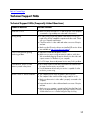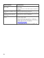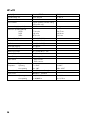
1
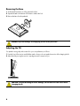
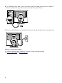
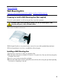
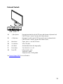
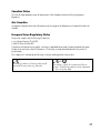
HP w20 / w22 LCD Monitor
User’s Guide
•
•
•
•
•
•
•
•
•
Preface
Safety and Maintenance Guidelines
Setup
Using the Monitor
Installing Drivers and Using the Auto-Adjustment Feature
Technical Support FAQs
Specifications
LCD Monitor Quality and Pixel Policy
Agency Regulatory Notices
The only warranties for HP products and services are set forth in the express warranty statements accompanying such
products and services. Nothing herein should be construed as constituting an additional warranty. HP shall not be liable for
technical or editorial errors or omissions contained herein.
HP assumes no responsibility for the use or reliability of its software on equipment that is not furnished by HP.
This document contains proprietary information that is protected by copyright. No part of this document may be photocopied,
reproduced, or translated to another language without the prior written consent of HP.
Hewlett-Packard Company
P.O. Box 4010
Cupertino, CA 95015-4010
USA
Copyright © 2006 Hewlett-Packard Development Company, L.P.
Microsoft and Windows are U.S. registered trademarks of Microsoft Corporation.
Adobe and Acrobat are trademarks of Adobe Systems Incorporated.
Bluetooth is a trademark owned by its proprietor and used by Hewlett-Packard Company under license.
HP supports lawful use of technology and does not endorse or encourage the use of its products for purposes other than those
permitted by copyright law.
The information in this document is subject to change without notice.
Part number: 436290-001
Back to Contents Page
Preface
About This Guide • Notational Conventions
About This Guide
This guide is intended for anyone who uses the HP w20 / w22 LCD Monitor. It describes the monitor’s features,
setup, and operation.
The sections are as follows:
•
•
•
•
•
•
•
•
Safety and Maintenance Guidelines
Setup
Using the Monitor
Installing Drivers and Using the Auto-Adjustment Feature
Technical Support FAQs
Specifications
LCD Monitor Quality and Pixel Policy
Agency Regulatory Notices
Notational Conventions
The following subsections describe notational conventions used in this document.
Notes, Cautions, and Warnings
Throughout this guide, blocks of text may be accompanied by an icon and printed in bold type or in italic type.
These blocks are notes, cautions, and warnings, and they are used as follows:
NOTE: A NOTE indicates important information that helps you make better use of your monitor.
CAUTION: A CAUTION indicates either potential damage to hardware or loss of data, and tells
you how to avoid the problem.
WARNING: A WARNING indicates the potential for bodily harm and tells you how to avoid the
problem.
Some warnings may appear in alternate formats and may be unaccompanied by an icon. In such cases, the
specific presentation of the warning is mandated by regulatory authority.
2
Back to Contents Page
Safety and Maintenance Guidelines
Important Safety Information • Safety Precautions • Maintenance Guidelines • Cleaning the Monitor
Important Safety Information
The power cord is designed for use with your monitor. To use a different cord, use only a power source and
connection compatible with this monitor. For information on the correct power cord set to use with your monitor,
see Power Cord Set Requirements.
WARNING: To reduce the risk of electric shock or damage to your equipment, do not disable
the power cord grounding feature. The grounding plug is an important safety feature. Connect
the equipment to a grounded (earthed) power outlet.
For your safety, be sure that the grounded power outlet you plug the power cord into is easily
accessible to the operator and located as close to the equipment as possible. To disconnect
power from the equipment, unplug the power cord from the power outlet by grasping the plug
firmly. Never pull on the cord.
Before connecting cables, disconnect power from the monitor by unplugging the power cord
from the electrical outlet.
Do not place anything on power cords or cables. Arrange them so that no one can accidentally
step on or trip over them. Do not pull on a cord or cable. When unplugging from the electrical
outlet, grasp the cord by its plug.
CAUTION: To protect your monitor, as well as your computer, connect all power cords for your
computer and its peripheral devices (such as a monitor, printer, or scanner) to a surge
protection device such as a power strip with surge protection or uninterruptible power
supply (UPS).
Not all power strips provide surge protection; the power strips must be specifically labeled as
having this ability. Use a power strip whose manufacturer offers a damage replacement policy
so you can replace your equipment if surge protection fails.
Safety Precautions
CAUTION: Avoid applying pressure to the LCD screen; doing so can cause damage.
• Use only a power source and connection compatible with this monitor, as indicated on the label/back plate of
the monitor.
• Be sure the total ampere rating of the products connected to the outlet does not exceed the current rating of the
electrical outlet, and the total ampere rating of the products connected to the cord does not exceed the rating
of the cord. Look on the power label to determine the ampere rating (Amps or A) for each device.
3
• Install your monitor near an outlet that you can easily reach. Disconnect the monitor by grasping the plug
firmly and pulling it from the outlet. Never disconnect the monitor by pulling the cord.
• Do not allow anything to rest on the power cord. Do not walk on the cord.
Maintenance Guidelines
To enhance the performance and extend the life of your monitor:
• Do not open your monitor cabinet or attempt to service this product yourself. If your monitor is not operating
properly or has been dropped or damaged, contact your HP authorized dealer, reseller, or service provider.
• Adjust only those controls that are described in the operating instructions.
• Turn your monitor off when not in use. You can substantially increase the life expectancy of your monitor by
•
•
•
•
•
using a screen saver and turning off the monitor when not in use.
Keep your monitor in a well-ventilated area, away from excessive light, heat, or moisture.
Slots and openings in the cabinet are provided for ventilation. These openings must not be blocked or
covered. Never push objects of any kind into cabinet slots or other openings.
Unplug your monitor from the wall outlet before cleaning.
Do not drop your monitor or place it on an unstable surface.
When removing the monitor pedestal base, you must lay the monitor face down on a soft area to prevent it
from getting scratched, defaced, or broken.
Cleaning the Monitor
The monitor is a high-quality optical device that requires special care when cleaning. To clean the monitor, follow
these steps:
1 Turn off the computer and the monitor.
2 Unplug your monitor from the wall outlet before cleaning.
CAUTION: Do not use benzene, thinner, ammonia, or any volatile substances to clean the
monitor screen or cabinet. These chemicals may damage the monitor. Do not use liquid
cleaners or aerosol cleaners. Never use water to clean an LCD screen.
3 Wipe the screen with a dry, soft, clean cloth.
• If the screen requires additional cleaning, use an antistatic screen cleaner.
4 Dust the monitor housing. Use a damp cloth to clean the cabinet.
• If the cabinet requires additional cleaning, use a clean cloth dampened with isopropyl alcohol.
5 Plug in the monitor.
6 Turn on the monitor and the computer.
4
Back to Contents Page
Setup
Base and Tilt • Cables • Wall Mounting Arm
Base and Tilt
Attaching the Base • Removing the Base • Adjusting the Tilt
Attaching the Base
1 Set the base on a flat surface, such as a table top.
2 Using both hands, position the pedestal over the base and press down firmly to lock in place. Make sure that
the base is securely locked in place before continuing with the setup procedure.
CAUTION: To prevent damage, avoid applying pressure to the panel front.
5
Removing the Base
1 Set the panel face-down on a flat, protected surface.
2 Squeeze the tabs in the bottom of the base to release the lock.
3 Remove the base from the pedestal.
CAUTION: To prevent damage, avoid applying pressure to the panel front.
Adjusting the Tilt
For optimal viewing, adjust the screen tilt to your own preference, as follows:
1 Face the front of the monitor and hold the stand so that you do not topple the monitor while changing the tilt.
2 Adjust the tilt by moving the monitor’s top edge toward or away from you.
CAUTION: To avoid breakage or other damage, do not touch the LCD screen while
changing the tilt.
6
Back to Contents Page
Cables
Attaching the Cables
Attaching the Cables
You can attach a VGA cable, a DVI-D cable (provided for select models only), or both to this monitor. To use
DVI, your computer must have a DVI-compliant graphics card. Connectors are found on the back of the monitor.
If both of these cables are installed, the source of input can be selected using the source button on the front
panel.
1 Turn off your computer.
2 Connect the built-in monitor speakers to the computer, using the audio cable (green connector).
3 If you are attaching a VGA cable, connect one end of the 15-pin D-Sub VGA cable (blue connector) to the
back of the monitor and connect the other end to the computer VGA port.
7
4 If you are attaching a DVI cable, connect one end of the 24-pin DVI-D cable (white connector) to the back of
the monitor (select models only) and connect the other end to the computer DVI port.
5 Connect one end of the power cord to the back of the monitor and plug the other end into a grounded outlet.
6 Turn on your monitor and computer.
If your monitor displays an image, installation is complete. If it does not display an image,
see Technical Support FAQs and Using the Monitor.
8
Back to Contents Page
Wall Mounting Arm
Preparing to Install a Wall Mounting Arm (Not supplied) • Installing a Wall Mounting Arm
Preparing to Install a Wall Mounting Arm (Not supplied)
This monitor can be attached to a wall mounting arm that you purchase separately.
CAUTION: Before disassembling the monitor, turn off the monitor power, and
disconnect all power, video, and audio cables.
1 Disconnect the cables from the monitor.
2 With the panel face-down on a protected surface, remove the screws and the pedestal/base attachment.
3 Follow the manufacturer’s instructions to assemble the wall mounting arm.
Installing a Wall Mounting Arm
1 Set the monitor screen down on a flat, soft, protected surface.
2 Place the wall mounting arm onto the back of the monitor. Line up the holes of the arm with the mounting holes
in the back of the monitor.
3 Insert four screws into the mounting holes and tighten.
4 Reconnect the cables. Refer to the user’s manual that came with the wall mounting arm (purchased separately)
for instructions on attaching it to the wall.
9
Back to Contents Page
Using the Monitor
Operating Instructions • External Controls • Settings •Setting the Optimal Resolution • Adjusting the Volume •
Locking and Unlocking the OSD • Adjusting OSD Settings
Operating Instructions
Control buttons are located on the front of the panel, as shown below. Use the menu button (C) to adjust the
display settings to your personal preferences:
•
•
•
•
•
Set up the monitor, attach the cables, and adjust the tilt as described in the Setup section above.
Press the power button (F) to turn the monitor on and off. The power indicator lights up when the monitor is on.
The monitor must be turned on for the other control buttons to work.
Set the resolution (Setting the Optimal Resolution) and adjust the volume (Adjusting the Volume).
Adjust the onscreen display (OSD) settings (Adjusting OSD Settings).
10
External Controls
A
– (Minus) button
Navigates backward through the OSD menu and decreases adjustment levels.
If the OSD menu is inactive, activates the Volume decrease.
B
+ (Plus) button
Navigates forward through the OSD menu and increases adjustment levels.
If the OSD menu is inactive, activates the Volume increase.
C
Menu button
Opens, selects, or exits the OSD menu.
D
Source button
VGA / DVI select.
E
Auto button
Automatically fine-tunes the image quality.
F
Power button
Turns the monitor on or off.
G
Power LED
Fully powered = green
Sleep mode = amber
Sleep timer mode = flashing amber
See Technical Support FAQs for more information.
11
Back to Contents Page
Settings
Setting the Optimal Resolution • Adjusting the Volume • Locking and Unlocking the OSD •
Adjusting OSD Settings
Setting the Optimal Resolution
The recommended resolution for this monitor is 1680 x 1050. To configure the monitor to this resolution,
complete the setup procedure and make sure that the monitor is connected to the computer. Turn the monitor on
and do the following:
1
2
3
4
5
6
Click Start.
Click Settings.
Click Control Panel.
Double-click Display.
Click Settings.
Set the resolution slide bar to 1680 x 1050.
NOTE: If 1680 x 1050 is not shown, download the monitor driver from the Web. See Using the Monitor for
instructions.
Adjusting the Volume
While the monitor is turned on but the OSD menu is inactive, press the volume increase and decrease (Plus and
Minus) buttons to adjust volume to the desired level. Volume can range from 0 (mute) to 100. The preset value
is 50.
Locking and Unlocking the OSD
To change the lock status of the on-screen display (from locked to unlocked, or from unlocked to locked) press
and hold the menu button for 10 seconds while the monitor is on. If the OSD is locked, the message “OSD Lock”
displays for 10 seconds.
12
Adjusting On-Screen Display Settings
Use the OSD menu to adjust the screen image and change settings. To access the OSD menu:
1 If the monitor is not already on, press the power button to turn the monitor on.
2 Press the menu button to activate the OSD menu.
3 Press the – (minus) and + (plus) buttons to navigate through the functions. Once the desired function is
highlighted, press the menu button again to activate it. If the selected function has a sub-menu, it displays.
Press – (minus) or + (plus) again to navigate through the sub-menu functions. Once the desired sub-function is
highlighted, press the menu button to activate it.
4 Press – (minus) or + (plus) to change the settings of the selected function.
5 To exit and save, select the Exit function. If you want to adjust another function, repeat steps 3–4.
NOTE: If the buttons remain untouched for 30 seconds while displaying a menu, new adjustments will be saved
and exit the menu.
13
OSD Menu
The table below shows the OSD menus and their functions at each level.
OSD Menu Levels
Level 1
Level 2
Brightness
Adjustment Scale
Level 3
Factory Preset
Y
Reset
Cancel
Save and Return
Contrast
Adjustment Scale
Y
Reset
Cancel
Save and Return
Volume
Adjustment Scale
Y
Image Control
Auto Adjustment
“Adjusting” Message
Y
Horizontal Position
Adjustment Scale
Y
Vertical Position
Adjustment Scale
Y
Custom Scaling
Fill to Screen
Fill to Aspect Ratio
Clock
Adjustment Scale
Y
Clock Phase
Adjustment Scale
Y
Cancel
Save and Return
Color
9300 K
6500 K
Custom Color
Y
Custom Color
Adjustment
Cancel
Save and Return
sRGB
Reset
Cancel
Save and Return
14
OSD Menu Levels (continued)
Level 1
Level 2
Language
Deutsch
Level 3
Factory Preset
Simplified Chinese
Japanese
English
English
Español
Français
Italiano
Nederlands
Cancel
Save and Return
Management
Power Saver
On / Off Selection
Y
Power On Recall
On / Off Selection
Y
Mode Display
On / Off Selection
Y
Power-On Status Display
On / Off Selection
Y
DDC/CI Support
On / Off Selection
Y
Sleep Timer
Timer Set Menu
Y
Default Video Input
Analog — VGA
Y
Digital — DVI
Cancel
Save and Return
OSD Control
Horizontal OSD Position
Adjustment Scale
Y
Vertical OSD Position
Adjustment Scale
Y
OSD Timeout
Adjustment Scale
Y
Cancel
Save and Return
Information
Factory Reset
Yes
No
Exit
15
Back to Contents Page
Installing Drivers and Using the Auto-Adjustment Feature
Downloading Drivers and Software
To download the latest version of drivers and software files from the HP Support Web site:
1
2
3
4
5
Refer to: http://www.hp.com/support
Select your country/region.
Select Download Drivers and Software.
Enter the model number of your monitor. The software download pages for your monitor will be displayed.
Download and install the driver and software files using the instructions in the download pages.
Using the Auto-Adjustment Function
Press the auto button to optimize the screen performance for VGA (analog).
Do not use this procedure if your monitor is using DVI input. If your monitor is using VGA (analog)
input, auto-adjustment can correct the following image quality conditions:
•
•
•
•
•
Fuzzy or unclear focus
Ghosting, streaking, or shadowing effects
Faint vertical bars
Thin, horizontal scrolling lines
An off-center picture
16
Back to Contents Page
Technical Support FAQs
Technical Support FAQs (Frequently Asked Questions)
Problem & Question
Possible Solutions
Power LED is not on.
• Make sure the power button is on and the power cord is properly
connected to a grounded power outlet and to the monitor.
No Plug & Play.
• In order for the Plug & Play feature of the monitor to work, you
need a Plug & Play compatible computer and video card. Check
with your computer manufacturer.
• Check the monitor’s video cable and make sure none of the pins
are bent.
• Make sure the HP monitor drivers are installed (HP monitor drivers
are available at: http://www.hp.com/support)
Picture is fuzzy and has ghosting
shadowing problem.
• Adjust the contrast and brightness controls.
• Make sure you are not using an extension cable or switch box.
We recommend plugging the monitor directly into the video card
output connector on the back of your computer.
• For VGA input, the auto-adjustment function may fix this problem.
Picture bounces, flickers or wave
pattern is present in the picture.
• Move electrical devices that may cause electrical interference as
far away from the monitor as possible.
• Use the maximum refresh rate your monitor is capable of at the
resolution you are using.
Monitor is stuck in “Active Off-Mode”.
• The computer power switch should be in the on position.
• The computer video card should be snugly seated in its slot.
• Make sure the monitor’s video cable is properly connected to the
computer.
• Inspect the monitor’s video cable and make sure none of the pins
are bent.
• Make sure your computer is operational by hitting the Caps Lock
key on the keyboard while observing the Caps Lock LED. The LED
should either turn on or off after hitting the Caps Lock key.
17
Problem & Question
Possible Solutions
Missing one of the primary colors (red,
green, or blue).
• Inspect the monitor’s video cable and make sure that none of the
Screen image is not centered or sized
properly.
• Adjust horizontal and vertical screen position.
• For VGA input, the auto-adjustment function may fix this problem.
Picture has color defects (white does
not look white).
• Adjust RGB color or select color temperature.
Unable to set the monitor to the optimal
resolution.
• Make sure that the graphics card supports the optimal
18
pins are bent.
• Make sure the monitor’s video cable is properly connected to the
computer.
resolution (1680 x 1050).
• Make sure that the latest supported driver is installed for the
graphics card. For HP and Compaq systems, you can download
the latest graphics driver for your system from:
http://www.hp.com/support
For other systems, refer to the Web site for your graphics card.
Back to Contents Page
Specifications
HP w20 • HP w22 • Preset Display Modes • Power Cord Set Requirements • Pin Assignments •
Plug and Play DDC2B Feature
All specifications represent the typical specifications provided by HP’s component manufacturers; actual
performance may vary either higher or lower.
HP w20
Display Type
20.1 inches, TFT LCD
51.11 cm
Viewable Image Size
20.1-inch diagonal
51.11 cm
Tilt
–5° to 20°
Face Treatment
Antiglare polarizer with hard coating
(select models only)
Maximum Weight (unpacked)
13 lb.
5.9 kg
Dimensions (including pedestal)
Height
Depth
Width
15.98 inches
9.84 inches
19.14 inches
405.89 mm
249.93 mm
486.16 mm
Optimum Display Resolution
1680 x 1050 (60 Hz)
Text Mode
720 x 400
Dot Pitch
0.258 (H) x 0.258 (V) mm
Horizontal Frequency
24 to 80 kHz
Vertical Refresh Rate
48 to 75 Hz
Audio Power Output
2W / channel @ PC 1 Vrms
Speaker (R/L)
2W / 16 ohm speaker
Power Consumption
<55 watts typical
Input Terminal
1. VGA connector
2. DVI-D connector
Environmental Requirements
Temperature:
Operating
Non-operating
41 to 104°F
–4 to 140°F
Relative Humidity
20 to 85% (non-condensing)
Power Source
100–240 V, 50–60 Hz
Altitude:
Operating
Non-operating
0 to 6,561.68 feet
0 to 40,000 feet
5 to 40°C
–20 to +60°C
0 to 2,000 m
0 to12,192 m
19
HP w22
Display Type
22 inches, TFT LCD
55.868 cm
Viewable Image Size
22-inch diagonal
55.868 cm
Tilt
–5° to 20°
Face Treatment
Antiglare polarizer with hard coating
(select models only)
Maximum Weight (unpacked)
13.89 lb.
6.3 kg
Dimensions (including pedestal)
Height
Depth
Width
17.18 inches
9.84 inches
20.74 inches
436.37 mm
249.94 mm
526.8 mm
Optimum Display Resolution
1680 x 1050 (60 Hz)
Text Mode
720 x 400
Dot Pitch
0.282 (H) x 0.282(V) mm
Horizontal Frequency
24 to 80 kHz
Vertical Refresh Rate
48 to 75 Hz
Audio Power Output
2W / channel @ PC 1 Vrms
Speaker (R/L)
2W / 16 ohm speaker
Power Consumption
<55 watts typical
Input Terminal
1. VGA connector
2. DVI-D connector
Environmental Requirements
Temperature:
Operating
Non-operating
41 to 104°F
–4 to 140°F
Relative Humidity
20 to 85% (non-condensing)
Power Source
100–240 V , 50–60 Hz
Altitude:
20
Operating
Non-operating
0 to 6,561.68 feet
0 to 40,000 feet
5 to 40°C
–20 to +60°C
0 to 2,000 m
0 to12,192 m
Preset Display Modes
Preset
Pixel Format
Horizontal
Frequency (kHz)
Vertical
Frequency (Hz)
1
640 x 480
31.47
59.94
2
640 x 480
37.50
75.00
3
720 x 400
31.47
70.08
4
800 x 600
37.88
60.32
5
800 x 600
46.88
75.00
6
832 x 624
49.72
74.55
7
1024 x 768
48.36
60.00
8
1024 x 768
60.02
75.03
9
1152 x 720
44.86
60.00
10
1152 x 870
68.68
75.06
11
1152 x 900
61.80
65.96
12
1280 x 768
47.396
60.00
13
1280 x 960
60.00
60.00
14
1280 x 1024
63.98
60.02
15
1280 x 1024
79.98
75.02
16
1440 x 900
55.94
59.89
17
1600 x 1000
61.648
60.00
18
1680 x 1050
65.29
60.00
21
Power Cord Set Requirements
The monitor power supply is provided with automatic line switching (ALS). This feature allows the monitor to
operate on input voltages in the range of 100–240V∿, 50/60 Hz, 1.5A.
The power cord set (flexible cord or wall plug) received with the monitor meets the requirements for use in the
country/region where the equipment was purchased.
If you need to obtain a power cord for a different country/region, you should purchase a power cord that is
approved for use in that country/region.
The power cord must be rated for the product and for the voltage and current marked on the product’s electrical
ratings label. The voltage and current rating of the cord should be greater than the voltage and current rating
marked on the product. In addition, the cross-sectional area of the wire must be a minimum of 0.75 mm² or
18AWG, and the length of the cord must be between 4.94 ft (1.5 m) and 12 ft (3.6 m). If you have questions
about the type of power cord to use, contact your HP-authorized service provider.
A power cord should be routed so that it is not likely to be walked on or pinched by items placed upon it or
against it. Particular attention should be paid to the plug, electrical outlet, and the point where the cord exits from
the product.
Pin Assignments
Pin Number
15-Pin Side of
the Signal Cable
1
Video-Red
2
Video-Green
3
Video-Blue
4
Ground
5
Detect Cable
6
GND-R
7
GND-G
8
GND-B
9
+5V
10
Ground
11
Ground
12
DDC-Serial data
13
H-sync
14
V-sync
15
DDC-Serial clock
22
Pin
No.
Signal Name
Pin
No.
Signal Name
Pin
No.
Signal Name
1
2
TMDS Data 2–
TMDS Data 2+
9
10
TMDS Data 1–
TMDS Data 1+
17
18
TMDS Data 0–
TMDS Data 0+
3
4
5
6
7
8
TMDS Data 2/4 Shield
TMDS Data 4–
TMDS Data 4+
DDC Clock
DDC Data
N.C.
11
12
13
14
15
16
TMDS Data 1/3 Shield
TMDS Data 3–
TMDS Data 3+
+5V Power
Ground (for +5V)
Hot Plug Detect
19
20
21
22
23
24
TMDS Data 0/5 Shield
TMDS Data 5–
TMDS Data 5+
TMDS Clock Shield
TMDS Clock+
TMDS Clock–
Plug and Play DDC2B Feature
This monitor is equipped with VESA DDC2B capabilities according to the VESA DDC STANDARD. It allows the
monitor to inform the host system of its identity and, depending on the level of DDC used, communicate
additional information about its display capabilities.
The DDC2B is a bi-directional data channel based on the I²C protocol. The host can request EDID information
over the DDC2B channel.
23
Back to Contents Page
LCD Monitor Quality and Pixel Policy
The HP LCD Monitor uses high-precision technology, manufactured according to high standards, to help
guarantee trouble-free performance. Nevertheless, the display may have cosmetic imperfections that appear as
small bright or dark spots. This is common to all LCD displays used in products supplied by all vendors and is not
specific to the HP LCD Monitor. These imperfections are caused by one or more defective pixels or subpixels.
• A pixel consists of one red, one green, and one blue subpixel.
• A defective whole pixel is always turned on (a bright spot on a dark background), or it is always off (a dark
spot on a bright background). The first is the more visible of the two.
• A defective subpixel (dot defect) is less visible than a defective whole pixel and is small and only visible on a
specific background.
To locate defective pixels, the monitor should be viewed under normal operating conditions and in normal
operating mode at a supported resolution and response rate, from a distance of approximately 50 cm (16 in).
We expect that, over time, the industry will continue to improve its ability to produce displays with fewer cosmetic
imperfections, and we will adjust guidelines as improvements are made.
For more information about your HP w20 / w22 LCD Monitor, refer to the HP Web site at:
http://www.hp.com/support
24
Back to Contents Page
Agency Regulatory Notices
Federal Communications Commission Notice
This equipment has been tested and found to comply with the limits for a Class B digital device, pursuant to
Part 15 of the FCC Rules. These limits are designed to provide reasonable protection against harmful interference
in a residential installation. This equipment generates, uses, and can radiate radio frequency energy and, if not
installed and used in accordance with the instructions, may cause harmful interference to radio communications.
However, there is no guarantee that interference will not occur in a particular installation. If this equipment does
cause harmful interference to radio or television reception, which can be determined by turning the equipment off
and on, the user is encouraged to try to correct the interference by one or more of the following measures:
•
•
•
•
Reorient or relocate the receiving antenna.
Increase the separation between the equipment and the receiver.
Connect the equipment into an outlet on a circuit different from that to which the receiver is connected.
Consult the dealer or an experienced radio or television technician for help.
Modifications
The FCC requires the user to be notified that any changes or modifications made to this device that are not
expressly approved by Hewlett-Packard Company may void the user’s authority to operate the equipment.
Cables
Connections to this device must be made with shielded cables with metallic RFI/EMI connector hoods to maintain
compliance with FCC rules and regulations.
25
Declaration of Conformity for Products Marked with FCC Logo,
United States Only
This device complies with Part 15 of the FCC Rules. Operation is subject to the following two conditions:
(1) this device may not cause harmful interference, and (2) this device must accept any interference received,
including interference that may cause undesired operation.
For questions regarding your product, contact:
Hewlett-Packard Company
P. O. Box 692000, Mail Stop 530113
Houston, Texas 77269-2000
Or
call: 1-(800)-474-6836
For questions regarding this FCC declaration, contact:
Hewlett-Packard Company
P. O. Box 692000, Mail Stop 510101
Houston, Texas 77269-2000
Or
call: 1-(281)-514-3333
To identify this product, refer to the part, series, or model number found on the product.
26
Canadian Notice
This Class B digital apparatus meets all requirements of the Canadian Interference-Causing Equipment
Regulations.
Avis Canadien
Cet appareil numérique de la classe B respecte toutes les exigences du Règlement sur le matériel brouilleur du
Canada.
European Union Regulatory Notice
This product complies with the following EU directives:
• Low Voltage Directive 73/23/EEC
• EMC Directive 89/336/EEC
Compliance with these directives implies conformity to applicable harmonized European standards (European
Norms) which are listed on the EU Declaration of Conformity issued by Hewlett-Packard for this product or
product family.
This compliance is indicated by the following conformity marking placed on the product:
xxxx*
This marking is valid for non-Telecom products and EU
harmonized Telecom products (e.g., Bluetooth).
This marking is valid for EU non-harmonized Telecom
products. *Notified body number (used only if applicable
— refer to the product label).
27
Disposal of Waste Equipment by Users in Private Households in the
European Union
This symbol on the product or on its packaging indicates that this product must not be disposed of with your other
household waste. Instead, it is your responsibility to dispose of your waste equipment by handing it over to a
designated collection point for the recycling of waste electrical and electronic equipment. The separate collection
and recycling of your waste equipment at the time of disposal will help to conserve natural resources and ensure
that it is recycled in a manner that protects human health and the environment. For more information about where
you can drop off your waste equipment for recycling, please contact your local city office, your household waste
disposal service or the shop where you purchased the product.
Japanese Notice
28
Japanese Power Cord Notice
Japanese Material Content Declaration
A Japanese regulatory requirement, defined by Specification JIS C 0950, 2005, mandates that manufacturers
provide Material Content Declarations for certain categories of electronic products offered for sale after
July 1, 2006. To view the JIS C 0950 material declaration for this product, visit www.hp.com/go/jisc0950.
Korean Notice
Materials Disposal
This HP product contains Mercury in the fluorescent lamp in the display LCD that might require special handling
at end-of-life.
Disposal of this material can be regulated because of environmental considerations. For disposal or recycling
information, please contact your local authorities or the Electronic Industries Alliance (EIA) (www.eiae.org).
29
HP Recycling Program
HP offers product end-of-life return programs for HP and other manufacturers’ hardware in several geographic
areas.
The terms and availability of these programs vary by geography because of differences in regulatory
requirements and local customer demand. For information on the HP recycling program, refer to the HP Web site
at: http://www.hp.com/recycle
EPA Energy Star® Compliance
Products marked with the ENERGY STAR® logo on the packaging box qualify with the U.S. Environmental
Protection Agency’s ENERGY STAR® guidelines for energy efficiency.
Products with the ENERGY STAR® label are designed to use less energy, help you save money on utility bills, and
help protect the environment.
ENERGY STAR® is a registered trademark owned by the U.S. government.
30
Congratulations!
The display you have just purchased carries the TCO’03 Display label.
This means that your display is designed, manufactured and tested
according to some of the strictest quality and environmental requirements
in the world. This makes for a high performance product, designed with
the user in focus and also minimizes the impact on our natural
environment.
Some of the features of the TCO’03 Display requirements:
Ergonomics
• Good visual ergonomics and image quality in order to improve the working environment for the user and to
reduce sight and strain problems. Important parameters are luminance, contrast, resolution, reflectance, color
rendition and image stability.
Energy
• Energy-saving mode after a certain time — beneficial both for the user and the environment.
• Electrical safety
Emissions
• Electromagnetic fields
• Noise emissions
31
Ecology
• The product is prepared for recycling and the manufacturer must have a certified environmental management
system such as EMAS or ISO 14 001.
• Restrictions on:
• chlorinated and brominated flame retardants and polymers.
• heavy metals such as cadmium, mercury and lead.
The requirements included in this label have been developed by TCO Development in co-operation with scientists,
experts, and users as well as manufacturers all over the world. Since the end of the 1980s, TCO has been
involved in influencing the development of IT equipment in a more friendly direction. Our labeling system started
with displays in 1992 and is now requested by users and IT-manufacturers all over the world.
For more information, please visit:
www.tcodevelopment.com
32