1
HP Smart Array Controllers for HP ProLiant Servers
User Guide
Abstract
This document includes feature, installation, and configuration information about HP Smart Array Controllers and is for the person who installs,
administers, and troubleshoots servers and storage systems. HP assumes you are qualified in the servicing of computer equipment and trained in
recognizing hazards in products with hazardous energy levels.
Part Number: 469988-009
August 2012
Edition: 9
© Copyright 2008, 2012 Hewlett-Packard Development Company, L.P.
The information contained herein is subject to change without notice. The only warranties for HP products and services are set forth in the express
warranty statements accompanying such products and services. Nothing herein should be construed as constituting an additional warranty. HP shall
not be liable for technical or editorial errors or omissions contained herein.
Microsoft® and Windows® are U.S. registered trademarks of Microsoft Corporation.
Bluetooth® is a trademark owned by its proprietor and used by Hewlett-Packard Company under license.
Contents
Component identification ............................................................................................................... 6
Controller components ............................................................................................................................... 6
P212 components............................................................................................................................ 6
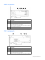
P222 components............................................................................................................................ 7
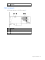
P400 components (model with front connectors) .................................................................................. 7
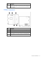
P400 components (model with back connectors) .................................................................................. 8
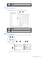
P410 components............................................................................................................................ 9
P411 components............................................................................................................................ 9
P420 components.......................................................................................................................... 10
P421 components.......................................................................................................................... 11
E500 components ......................................................................................................................... 11
P700m components ....................................................................................................................... 12
P711m components ....................................................................................................................... 13
P712m components ....................................................................................................................... 13
P721m components ....................................................................................................................... 14
P800 components.......................................................................................................................... 14
P812 components.......................................................................................................................... 15
P822 components.......................................................................................................................... 16
Controller board runtime LEDs ................................................................................................................... 16
P212, P410, and P411 LEDs .......................................................................................................... 17
E500 and P400 LEDs ..................................................................................................................... 18
P222 LEDs .................................................................................................................................... 19
P420 LEDs .................................................................................................................................... 19
P421 LEDs .................................................................................................................................... 20
P700m LEDs ................................................................................................................................. 21
P711m LED................................................................................................................................... 22
P712m LED................................................................................................................................... 22
P721m LEDs ................................................................................................................................. 23
P800 LEDs .................................................................................................................................... 23
P812 LEDs .................................................................................................................................... 25
P822 LEDs .................................................................................................................................... 26
FBWC module LEDs ................................................................................................................................. 26
FBWC module LEDs (P410, P411, P711m, P812) ............................................................................. 26
FBWC module LEDs (P222, P420, P421, P721m, P822) .................................................................... 27
Battery pack LEDs .................................................................................................................................... 28
Specifications ............................................................................................................................. 30
Memory and storage capacity conventions ................................................................................................. 30
RAID conventions .................................................................................................................................... 30
Smart Array Advanced Pack ..................................................................................................................... 30
Required hardware ........................................................................................................................ 31
Supported servers and server blades .......................................................................................................... 31
Specifications common to all controller models ............................................................................................ 32
Controller specifications by model ............................................................................................................. 33
E500, P411, and P421 specifications .............................................................................................. 33
P400, P410, and P420 specifications .............................................................................................. 34
P212 and P222 specifications ........................................................................................................ 34
Contents
3
P700m, P711m, P712m, and P721m specifications .......................................................................... 35
P800, P812, and P822 specifications .............................................................................................. 35
Battery pack service life ........................................................................................................................... 36
Installation and configuration ....................................................................................................... 37
Procedures for controllers in a server.......................................................................................................... 37
Installing a stand-up controller in an unconfigured server .................................................................... 37
Installing a stand-up controller in a previously configured server .......................................................... 38
Installing the controller board .......................................................................................................... 38
Connecting internal storage ............................................................................................................ 39
SAS cable part numbers ................................................................................................................. 40
Procedures for controllers in a server blade................................................................................................. 40
Installing a mezzanine controller in an unconfigured server blade ........................................................ 40
Installing a mezzanine controller in a previously configured server blade .............................................. 41
Installing the mezzanine controller board .......................................................................................... 42
Configuration tools .................................................................................................................................. 43
Option ROM Configuration for Arrays ............................................................................................. 43
ROM-Based Setup Utility ................................................................................................................. 44
Array configuration tools .......................................................................................................................... 44
System maintenance tools ......................................................................................................................... 45
Updating firmware ........................................................................................................................ 45
Installing device drivers .................................................................................................................. 45
Installing Management Agents ........................................................................................................ 46
Diagnostic tools ...................................................................................................................................... 46
Upgrade and replacement procedures .......................................................................................... 48
Replacing the battery on the P212, P410, and P411 models ........................................................................ 48
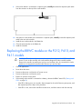
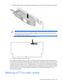
Replacing the FBWC module on the P410 and P411 models ........................................................................ 49
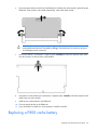
Replacing the BBWC module on the P212, P410, and P411 models ............................................................. 50
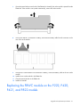
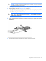
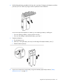
Replacing the FBWC module on the P222, P420, P421, and P822 models .................................................... 51
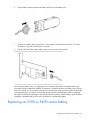
Installing an E500 or P400 cache battery ................................................................................................... 53
Replacing an E500 or P400 cache battery ................................................................................................. 54
Replacing the E500 or P400 cache ........................................................................................................... 55
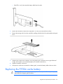
Replacing the P700m cache battery........................................................................................................... 56
Removing a P711m capacitor pack ........................................................................................................... 59
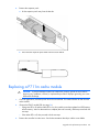
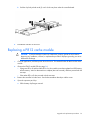
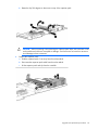
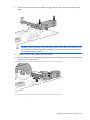
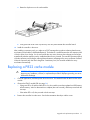
Replacing a P711m cache module ............................................................................................................ 60
Replacing a P712m cache module ............................................................................................................ 63
Replacing the FBWC module on the P721m ............................................................................................... 64
Replacing a P800 cache battery ............................................................................................................... 65
Replacing the P800 cache module or controller ........................................................................................... 70
Replacing a P812 cache module ............................................................................................................... 73
Replacing a P822 cache module ............................................................................................................... 77
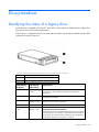
Drive procedures ........................................................................................................................ 79
Identifying the status of a legacy drive ....................................................................................................... 79
Identifying the status of an HP SmartDrive ................................................................................................... 80
Recognizing drive failure.......................................................................................................................... 81
Effects of a drive failure .................................................................................................................. 81
Compromised fault tolerance .......................................................................................................... 82
Recovering from compromised fault tolerance.................................................................................... 82
Replacing drives ..................................................................................................................................... 82
Before replacing drives .................................................................................................................. 83
Automatic data recovery (rebuild) .................................................................................................... 83
Upgrading drive capacity ............................................................................................................... 86
Contents
4
Moving drives and arrays ........................................................................................................................ 86
Adding drives ......................................................................................................................................... 87
Electrostatic discharge ................................................................................................................. 89
Preventing electrostatic discharge .............................................................................................................. 89
Grounding methods to prevent electrostatic discharge .................................................................................. 89
Regulatory compliance notices ..................................................................................................... 90
Federal Communications Commission notice ............................................................................................... 90
FCC rating label ............................................................................................................................ 90
FCC Notice, Class A Equipment ...................................................................................................... 90
FCC Notice, Class B Equipment ...................................................................................................... 90
Declaration of conformity for products marked with the FCC logo, United States only ....................................... 91
Modifications .......................................................................................................................................... 91
Cables ................................................................................................................................................... 91
Canadian notice (Avis Canadien) .............................................................................................................. 91
European Union regulatory notice ............................................................................................................. 92
BSMI notice ............................................................................................................................................ 92
Chinese notice ........................................................................................................................................ 93
Japanese notice ...................................................................................................................................... 93
Korean notice ......................................................................................................................................... 93
Battery replacement notice........................................................................................................................ 93
Taiwan battery recycling notice ................................................................................................................. 94
Acronyms and abbreviations ........................................................................................................ 95
Documentation feedback ............................................................................................................. 97
Index ......................................................................................................................................... 98
Contents
5
Component identification
Controller components
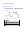
For cabling configuration and troubleshooting purposes, connector names are silk-screened on the controller.
For connector and other component locations, see the appropriate controller-specific section.
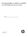
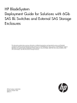
P212 components
Item
Description
1
Port 1E (Mini-SAS 4x connector)
2
Port 2I (Mini-SAS 4x connector)
3
Cache module (also known as array accelerator)
4
Status LEDs (runtime LEDs). For more information, see "Controller
board runtime LEDs (on page 16)."
5
(On rear of cache) Connector for the cable to an optional cache
battery that upgrades the cache to BBWC
Component identification 6
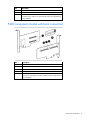
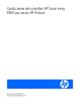
P222 components
For LED locations and status, see "P222 LEDs (on page 19)."
Item
Description
1
Port 1E (Mini-SAS 4x connector)
2
Port 2I (Mini-SAS 4x connector)
3
Cache module (also known as array accelerator)
4
Capacitor pack cable connector
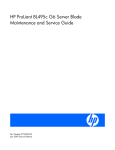
P400 components (model with front connectors)
Item
Description
1
Port 2I (SAS 4x connector)
2
Port 1I (SAS 4x connector)
Component identification 7
Item
Description
3
Cache module connectors
4
Runtime LEDs. See "Controller board runtime LEDs (on page 16)."
5
Cache module (also known as array accelerator), showing the
connector for the cable to an optional battery pack that upgrades the
cache to BBWC
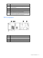
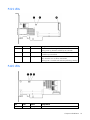
P400 components (model with back connectors)
Item
Description
1
Cache module connectors
2
Port 1I (SAS 4x connector)
3
Runtime LEDs. See "Controller board runtime LEDs (on page 16)."
4
Port 2I (SAS 4x connector)
5
Cache module (also known as array accelerator), showing the
connector for the cable to an optional battery pack that upgrades the
cache to BBWC
Component identification 8
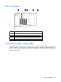
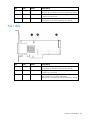
P410 components
Item
Description
1
Cache module (also known as array accelerator)
2
Runtime LEDs. See "Controller board runtime LEDs (on page 16)."
3
(On rear of cache) Connector for the cable to an optional cache
battery that upgrades the cache to BBWC
(Not shown) In place of the BBWC option, the controller can support a
FBWC module and capacitor pack.
4
Port 1I (Mini-SAS 4x connector)
5
Port 2I (Mini-SAS 4x connector)
P411 components
Item
Description
1
Ports 1E and 2E (Mini-SAS 4x connectors)
2
Cache module (also known as array accelerator)
3
Runtime LEDs. See "Controller board runtime LEDs (on page 16)."
4
(On rear of cache) Connector for the cable to an optional cache
battery that upgrades the cache to BBWC
(Not shown) In place of the BBWC option, the controller can support a
Component identification 9
Item
Description
FBWC module and capacitor pack.
P420 components
For LED locations and status, see "P420 LEDs (on page 19)."
Item
Description
1
Cache module (also known as array accelerator)
2
Capacitor pack cable connector
3
Port 2I (Mini-SAS 4x connector)
4
Port 1I (Mini-SAS 4x connector)
Component identification 10
P421 components
For LED locations and status, see "P421 LEDs (on page 20)."
Item
Description
1
Port 1E (Mini-SAS 4x connector)
2
Port 2E (Mini-SAS 4x connector)
3
Cache module (also known as array accelerator)
4
Capacitor pack cable connector
E500 components
Item
Description
1
Port 1E (Mini-SAS 4x connector)
2
Port 2E (Mini-SAS 4x connector)
Component identification 11
Item
Description
3
Cache module (also known as array accelerator), showing the
connector for the cable to an optional battery pack that upgrades the
cache to BBWC
P700m components
Item
Description
1
Runtime LEDs. See "Controller board runtime LEDs (on page 16)."
2
Connector (not used on HP ProLiant servers)
3
Cache module (also known as array accelerator)
4
Connector for the cable to an optional cache battery that upgrades the
cache to BBWC. This connector is absent on some P700m models.
5
Mezzanine connector
Component identification 12
P711m components
Item
Description
1
Mezzanine connector
2
Runtime LED. See "Controller board runtime LEDs (on page 16)."
3
Cache module
P712m components
Item
Description
1
Mezzanine connector
2
Runtime LED. See "Controller board runtime LEDs (on page 16)."
3
SAS/SATA connector
4
SAS/SATA connector
Component identification 13
Item
Description
5
Cache module (not available on all models)
P721m components
For LED locations and status, see "P721m LEDs (on page 23)."
Item
Description
1
Cache module (also known as array accelerator)
2
Capacitor pack cable connector
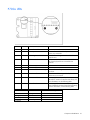
P800 components
Component identification 14
Item
Description
1
Ports 1E and 2E (Mini-SAS 4x connectors)
2
Heartbeat LED (flashes green when operating normally and amber if
the board has failed)
3
Activity LED for external ports
4
Port 3I (Mini-SAS 4x connector)
5
Port 4I (Mini-SAS 4x connector)
6
Cache module (also known as array accelerator)
7
(Optional) Batteries for cache module
Two batteries are normally sufficient, but you can add a third battery to
provide extra security against loss of system power.
P812 components
Item
Description
1
Ports 1E, 2E, 3E, and 4E (Mini-SAS 4x connectors)
2
Port 6I (Mini-SAS 4x connector)
3
Port 5I (Mini-SAS 4x connector)
4
Cache module (also known as array accelerator)
5
Capacitor pack for cache module
Component identification 15
P822 components
Item
Description
1
Ports 1E, 2E, 3E, and 4E (Mini-SAS 4x connectors)
2
Port 5I (Mini-SAS 4x connector)
3
Port 6I (Mini-SAS 4x connector)
4
Cache module
5
Capacitor pack connector for cache module
Controller board runtime LEDs
Immediately after you power up the server, the controller runtime LEDs illuminate briefly in a predetermined
pattern as part of the POST sequence. At all other times during server operation, the illumination pattern of
the runtime LEDs indicates the status of the controller. To determine the controller status, see the appropriate
controller-specific section.
Component identification 16
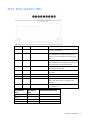
P212, P410, and P411 LEDs
LED ID
Color
Name
Comments
1
Amber
DS9: System Error
The controller ASIC has locked up and cannot
process any commands.
2
Green
DS8: Idle Task
This LED, together with the Gas Pedal LED (next
item), indicates the amount of controller CPU
activity. For more information, see the following
table.
3
Green
DS7: Gas Pedal
This LED, together with the Idle Task LED (previous
item), indicates the amount of controller activity. For
more information, see the following table.
4
Green
DS6: Heartbeat
When the controller is in good health, this LED
flashes every two seconds.
5
Green
DS5: Pending Command
The controller is working on a command from the
host driver.
6
Green
DS4: Port 1 Active
Port 1 is active.
7
Green
DS3: Port 2 Active
Port 2 is active.
8
Amber
DS2: Drive Failure
To determine which drive has failed, check the Fault
LED of each physical drive connected to the
controller.
9
Amber
DS1: Diagnostics Error
One of the server diagnostics utilities has detected
a controller error.
Gas pedal LED
status
Idle task LED
status
Controller CPU activity level
Off
Flashing
0-25%
Flashing
Off
25-50%
On steadily
Off
50-75%
On steadily
On steadily
75-100%
Component identification 17
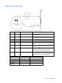
E500 and P400 LEDs
LED ID
Color
Name
Comments
1
Amber
CR14: Controller Lockup
The controller ASIC has locked up and cannot process
any commands.
2
Amber
CR13: Drive Failure
To determine which drive has failed, check the Fault
LED of each physical drive connected to the controller.
3
Green
CR3: Activity
Port 2E on the E500, or port 2I on the P400, is active.
4
Green
CR8: Activity
Port 1E on the E500, or port 1I on the P400, is active.
5
Green
CR5: Command Outstanding The controller is working on a command from the host
driver.
6
Green
CR6: Heartbeat
When the controller is in good health, this LED flashes
every two seconds.
7
Green
CR4: Gas Pedal
This LED, together with the Idle Task LED (next item),
indicates the amount of controller CPU activity. For
more information, see the following table.
8
Green
CR7: Idle Task
This LED, together with the Gas Pedal LED (previous
item), indicates the amount of controller CPU activity.
For more information, see the following table.
Gas Pedal LED status Idle Task LED status
Controller CPU activity level
Off
Flashing
0–25%
Flashing
Off
25–50%
On steadily
Off
50–75%
On steadily
On steadily
75–100%
Component identification 18
P222 LEDs
Item
Color
Name
Interpretation
1
Green
Heartbeat
When the controller is in good health, this LED flashes at 1 Hz.
During power up, this LED is solid for up to 2 seconds.
2
Red
Fault
When an error occurs, this LED is on. During power up, this LED
is solid for up to 2 seconds.
3
Amber
Debug
On = Controller is in reset.
Off = Controller is in an idle or runtime state.
Flashing 5 Hz = Controller and cache are performing a backup.
Item
Color
Name
Interpretation
1
Amber
Debug
On = Controller is in reset state.
P420 LEDs
Component identification 19
Item
Color
Name
Interpretation
Off = Controller is in an idle or runtime state.
Flashing 5 Hz = Controller and cache are performing a backup.
2
Red
Fault
When an error occurs, this LED is on. During power up, this LED
is solid for up to 2 seconds.
3
Green
Heartbeat
When the controller is in good health, this LED flashes at 1 Hz.
During power up, this LED is solid for up to 2 seconds.
Item
Color
Name
Interpretation
1
Green
Heartbeat
When the controller is in good health, this LED flashes at 1 Hz.
During power up, this LED is solid for up to 2 seconds.
2
Red
Fault
When an error occurs, this LED is on. During power up, this LED
is solid for up to 2 seconds.
3
Amber
Debug
On = Controller is in reset.
Off = Controller is in an idle or runtime state.
Flashing 5 Hz = Controller and cache are performing a backup.
P421 LEDs
Component identification 20
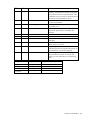
P700m LEDs
LED ID
Color
Name
Comments
1
Amber
CR10: Thermal Alert
This LED is not used.
2
Amber
CR9: System Error
The controller ASIC has locked up and cannot
process any commands.
3
Amber
CR1: Diagnostics Error
One of the server diagnostics utilities has detected a
controller error.
4
Amber
CR2: Drive Failure
To determine which drive has failed, check the Fault
LED of each physical drive connected to the
controller.
5
Green
CR3: Activity
Port 2 is active.
6
Green
CR4: Activity
Port 1 is active.
7
Green
CR5: Command Outstanding
The controller is working on a command from the
host driver.
8
Green
CR6: Controller Heartbeat
When the controller is in good health, this LED
flashes every two seconds.
9
Green
CR7: Gas Pedal
This LED, together with the Idle Task LED (next item),
indicates the amount of controller CPU activity. For
more information, see the following table.
10
Green
CR8: Idle Task
This LED, together with the Gas Pedal LED (previous
item), indicates the amount of controller CPU activity.
For more information, see the following table.
Gas Pedal LED status Idle Task LED status Controller CPU activity level
Off
Flashing
0–25%
Flashing
Off
25–50%
On steadily
Off
50–75%
On steadily
On steadily
75–100%
Component identification 21
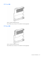
P711m LED
Name: Controller heartbeat LED (CR6)
Status: Flashes every 2 seconds = The controller is functioning properly.
P712m LED
Name: Controller heartbeat LED (CR6)
Status: Flashes every 2 seconds = The controller is functioning properly.
Component identification 22
P721m LEDs
Color
Name
Interpretation
Green
Heartbeat
When the controller is in good health, this LED flashes at 1 Hz.
During power up, this LED is solid for up to 2 seconds.
Amber
Fault
When an error occurs, this LED is on. During power up, this LED
is solid for up to 2 seconds.
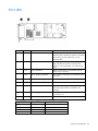
P800 LEDs
Component identification 23
LED ID
Color
Name
Comments
1
Green
CR502: Expander Heartbeat
This LED flashes every two seconds during normal
operation. If the LED glows steadily, the expander
cannot function due to an internal problem. If the
LED flashes twice per second, the expander cannot
function because the NVRAM is corrupt.
2
Amber
CR510: System Error
The controller ASIC has locked up and cannot
process any commands.
3
Amber
CR509: Diagnostics Error
One of the server diagnostics utilities has detected
a controller error.
4
Amber
CR500: Drive Failure
To determine which drive has failed, check the Fault
LED of each physical drive connected to the
controller.
5
Green
CR508: Activity
Port 4I is active.
6
Green
CR507: Activity
Port 3I is active.
7
Green
CR506: Command Outstanding
The controller is working on a command from the
host driver.
8
Green
CR505: Controller Heartbeat
When the controller is in good health, this LED
flashes every two seconds.
9
Green
CR504: Gas Pedal
This LED, together with the Idle Task LED (next item),
indicates the amount of controller CPU activity. For
more information, see the following table.
10
Green
CR503: Idle Task
This LED, together with the Gas Pedal LED (previous
item), indicates the amount of controller CPU
activity. For more information, see the following
table.
Gas pedal LED status Idle task LED status Controller CPU activity level
Off
Flashing
0–25%
Flashing
Off
25–50%
On steadily
Off
50–75%
On steadily
On steadily
75–100%
Component identification 24
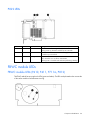
P812 LEDs
Item
Color
Name
Comments
1
Green
CR76: Idle Task
This LED, together with the Gas Pedal LED
(following item), indicates the amount of controller
CPU activity. For more information, see the
following table.
2
Green
CR75: Gas Pedal
This LED, together with the Idle Task LED (previous
item), indicates the amount of controller CPU
activity. For more information, see the following
table.
3
Green
CR74: Heartbeat
When the controller is in good health, this LED
flashes every 2 seconds.
4
Green
CR73: Pending Command
The controller is working on a command from the
host driver.
5
Green
CR72: Port 1 Activity
Port 1 is active.
6
Green
CR 71: Port 2 Activity
Port 2 is active.
7
Amber
CR78: Drive Failure
To determine which drive has failed, check the Fault
LED of each physical drive connected to the
controller.
8
Amber
CR77: Diagnostics Error
One of the server diagnostics utilities has detected
a controller error.
9
Green
CR82: MIPS ready
The embedded SAS expander is active.
Gas pedal LED status Idle task LED status Controller CPU activity level
Off
Flashing
0–25%
Flashing
Off
25–50%
On
Off
50–75%
On
On
75–100%
Component identification 25
P822 LEDs
Item
Color
Name
Interpretation
1
Green
Heartbeat
When the controller is in good health, this LED flashes at 1 Hz.
During power up, this LED is solid for up to 2 seconds.
2
Red
Fault
When an error occurs, this LED is on. During power up, this LED
is solid for up to 2 seconds.
3
Amber
Debug
On = Controller is in reset.
Off = Controller is in an idle or runtime state.
Flashing 5 Hz = Controller and cache are performing a backup.
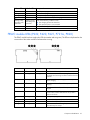
FBWC module LEDs
FBWC module LEDs (P410, P411, P711m, P812)
The FBWC module has two single-color LEDs (green and amber). The LEDs are duplicated on the reverse side
of the cache module to facilitate status viewing.
Component identification 26
1 Green LED
2 Amber LED
Interpretation
Off
On
A backup is in progress.
Flashing (1 Hz)
On
A restore is in progress.
Flashing (1 Hz)
Off
The capacitor pack is charging.
On
Off
The capacitor pack has completed charging.
Flashing (2 Hz)
Alternating with
amber LED
Flashing (2 Hz)
Alternating with
green LED
One of the following conditions exists:
On
On
The flash code image failed to load.
Off
Off
The flash code is corrupt.
•
•
The charging process has timed out.
The capacitor pack is not connected.
FBWC module LEDs (P222, P420, P421, P721m, P822)
The FBWC module has three single-color LEDs (one amber and two green). The LEDs are duplicated on the
reverse side of the cache module to facilitate status viewing.
1 - Amber
2 - Green
3 - Green
Interpretation
Off
Off
Off
The cache module is not powered.
Off
Flashing 0.5 Hz
Flashing 0.5 Hz
The cache microcontroller is executing from within its
boot loader and receiving new flash code from the host
controller.
Off
Flashing 1 Hz
Flashing 1 Hz
The cache module is powering up, and the capacitor
pack is charging.
Off
Off
Flashing 1 Hz
The cache module is idle, and the capacitor pack is
charging.
Off
Off
On
The cache module is idle, and the capacitor pack is
charged.
Off
On
On
The cache module is idle, the capacitor pack is charged,
and the cache contains data that has not yet been
written to the drives.
Off
Flashing 1 Hz
Off
A backup is in progress.
Off
On
Off
The current backup is complete with no errors.
Flashing 1 Hz
Flashing 1 Hz
Off
The current backup failed, and data has been lost.
Flashing 1 Hz
Flashing 1 Hz
On
A power error occurred during the previous or current
boot. Data may be corrupt.
Component identification 27
1 - Amber
2 - Green
3 - Green
Interpretation
Flashing 1 Hz
On
Off
An overtemperature condition exists.
Flashing 2 Hz
Flashing 2 Hz
Off
The capacitor pack is not attached.
Flashing 2 Hz
Flashing 2 Hz
On
The capacitor has been charging for 10 minutes, but
has not reached sufficient charge to perform a full
backup.
On
On
Off
The current backup is complete, but power fluctuations
occurred during the backup.
On
On
On
The cache module microcontroller has failed.
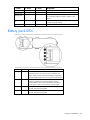
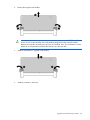
Battery pack LEDs
Item
Color
Description
1
Green
System Power LED. This LED is on when the system is
powered up and 12 V system power is available. This
power supply is used to maintain the battery charge and
provide supplementary power to the cache microcontroller.
2
Green
Auxiliary Power LED. This LED is on when 3.3V auxiliary
voltage is detected. The auxiliary voltage is used to
preserve BBWC data and is available any time that the
system power cords are connected to a power supply.
3
Amber
Battery Health LED. To interpret the illumination patterns of
this LED, see the following table.
4
Green
BBWC Status LED. To interpret the illumination patterns of
this LED, see the following table.
Component identification 28
LED3 pattern
LED4 pattern
Interpretation
Off
Flashing (2 Hz)
The system is powered down, and the cache contains data that has not
yet been written to the drives. Restore system power as soon as
possible to prevent data loss.
Data preservation time is extended any time that 3.3 V auxiliary
power is available, as indicated by LED 2. In the absence of auxiliary
power, battery power alone preserves the data. A fully-charged
battery can normally preserve data for at least 2 days.
The battery lifetime also depends on the cache module size. For more
information, see the controller QuickSpecs on the HP website
(http://www.hp.com).
Off
Double flash, then The cache microcontroller is waiting for the host controller to
pause
communicate.
Off
Flashing (1 Hz)
The battery pack is below the minimum charge level and is being
charged. Features that require a battery (such as write cache, capacity
expansion, stripe size migration, and RAID migration) are unavailable
temporarily until charging is complete. The recharge process takes
between 15 minutes and 2 hours, depending on the initial capacity of
the battery.
Off
On
The battery pack is fully charged, and posted write data is stored in the
cache.
Off
Off
The battery pack is fully charged, and no posted write data exists in
the cache.
Flashing (1 Hz)
Flashing (1 Hz)
An alternating green and amber flashing pattern indicates that the
cache microcontroller is executing from within its boot loader and
receiving new flash code from the host controller.
On
—
A short circuit exists across the battery terminals or within the battery
pack. BBWC features are disabled until the battery pack is replaced.
The life expectancy of a battery pack is typically more than 3 years.
Flashing (1 Hz)
—
An open circuit exists across the battery terminals or within the battery
pack. BBWC features are disabled until the battery pack is replaced.
The life expectancy of a battery pack is typically more than 3 years.
Component identification 29
Specifications
Memory and storage capacity conventions
Memory capacities are specified using binary prefixes:
•
KiB = 210 bytes
•
MiB = 220 bytes
•
GiB = 230 bytes
•
TiB = 240 bytes
Storage capacities are specified using SI prefixes:
•
KB = 103 bytes
•
MB = 106 bytes
•
GB = 109 bytes
•
TB = 1012 bytes
Older, and other, documentation may use SI prefixes for binary values.
Actual available memory capacity and actual formatted storage capacity for devices are less than specified
values.
RAID conventions
HP uses the following naming convention for RAID levels:
•
RAID 0
•
RAID 1+0
•
RAID 5
•
RAID 50
•
RAID 6
•
RAID 60
•
RAID 1 (ADM)
•
RAID 10 (ADM)
RAID 50 and RAID 60 are also known in the industry as RAID 5+0 and RAID 6+0, respectively.
Smart Array Advanced Pack
SAAP is a collection of additional and advanced controller features embedded in the firmware of select
Smart Array controllers.
Specifications
30
To access SAAP features, activate the software with a registered license key.
SAAP 1.0 provides the following features:
•
RAID 6 (ADG)
•
RAID 60
•
Advanced Capacity Expansion
•
Mirror splitting and recombining in offline mode
•
Drive Erase
•
Performance optimization for video on demand
•
Dual domain
SAAP 2.0 includes all v1.0 features and also provides the following additional features:
•
RAID 1 (ADM) and RAID 10 (ADM)
•
Capability for moving and deleting individual LUNs
•
Split mirror backup and rollback of RAID 1, 1+0, 1 (ADM) and 10 (ADM) mirrors
•
Heal Array
To access SAAP features, you must purchase a license key from HP. To obtain a license key, see the SAAP
product page on the HP website (http://www.hp.com/go/SAAP).
To install the license key and activate SAAP, use a supported array configuration tool:
•
Option ROM Configuration for Arrays (ORCA)
•
HP Array Configuration Utility (ACU)
For registration procedures, see the Configuring Arrays for HP Smart Array Controllers Reference Guide
available on the controller Documentation CD or the ACU product page on the HP website
(http://h18004.www1.hp.com/products/servers/proliantstorage/software-management/acumatrix/inde
x.html).
Required hardware
For a list of Smart Array controllers that support SAAP, see the SAAP product page on the HP website
(http://www.hp.com/go/SAAP).
To support some controller features, the controller may also require a hardware configuration that includes
the following cache (array accelerator) options:
•
A cache module that is 256 MiB or larger
•
A compatible battery pack or capacitor pack
To obtain these options, contact an HP authorized reseller or see the HP website
(http://www.hp.com/products/smartarray).
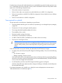
Supported servers and server blades
Use the following table to identify server and server blade support for HP Smart Array controllers.
Specifications
31
Controller
Speed
Supported product
P222
6 Gb/s
ProLiant Gen8 servers*
P420
6 Gb/s
ProLiant Gen8 servers*
P421
6 Gb/s
ProLiant Gen8 servers
P212
6 Gb/s
ProLiant G6/G7 servers
P410
6 Gb/s
ProLiant G6/G7 servers
P411
6 Gb/s
ProLiant G6/G7 servers
P711m
6 Gb/s
ProLiant G6/G7 server blades
P712m
6 Gb/s
ProLiant G6/G7 server blades
P721m
6 Gb/s
ProLiant Gen8 server blades**
P812
6 Gb/s
ProLiant G6/G7 servers
P822
6 Gb/s
ProLiant Gen8 servers†
P400
3 Gb/s
ProLiant G4/G5 servers
P700m
3 Gb/s
ProLiant G4/G5 server blades
P800
3 Gb/s
ProLiant G4/G5 servers and select G6 servers
E500
3 Gb/s
ProLiant G4/G5 servers
* The P222 controller is not supported in the HP ProLiant ML350p Gen8 server. The P420 is not supported in slot 3 or
slot 4 of the HP ProLiant ML350p Gen8 server.
** The P721m controller is not supported in expansion slot 1 of HP ProLiant Gen8 server blades.
† The HP P822 Smart Array Controller is not supported in all slots in all HP ProLiant Gen8 servers. See the table below
for slots that are not supported, or that require special configuration.
Server
Rules
DL360e Gen8
•
•
DL380e Gen8
P822 is not supported in PCI slot 4.
DL380p Gen8
P822 is not supported in PCI slot 3.
DL385p Gen8
P822 is not supported in PCI slot 3.
ML350p Gen8
•
•
ML350e Gen8
P822 supported in slot 2 only
P822 supported in slot 1 only
Requires Smart Array cable kit part number 672242-B21
P822 is not supported in slots 1, 2, 5, 6, 7, 8, or 9.
When installing P822 in slot 3, slot 4 cannot be populated.
For more information on installing the controller, see the server user guide.
For the latest support information, see the controller QuickSpecs on the HP website
(http://h18000.www1.hp.com/products/quickspecs/ProductBulletin.html). At the website, choose the
geographic region, and then locate the product by name or product category.
Specifications common to all controller models
This section describes the most commonly referenced controller features. For other features, specifications,
and information about system requirements, see the HP website
(http://www.hp.com/products/smartarray). To get the full benefit of all controller features, be sure that the
controller is loaded with the latest firmware.
Feature
Details
Temperature range
Operating, 10° to 55°C (50° to 131°F)
Storage, -30° to 60°C (-22° to 140°F)
Specifications
32
Relative humidity (noncondensing) Operating, 10% to 90%
Storage, 5% to 90%
Time required to recharge battery1 From 15 minutes to 2 hours 40 minutes, depending on the initial battery
charge level
Duration of battery backup1
If the battery is fully charged and less than 3 years old, more than 2 days
The battery pack provides a continuous charge to store the cached data
in DDR memory.
Battery life expectancy1
3 years
For more information, see "Battery pack service life (on page 36)."
Time required to recharge
capacitor2
5 minutes or less
Duration of capacitor backup2
80 seconds
The capacitor pack provides a sufficient duration to transfer the cached
data from DDR memory to flash memory, where the data remains
indefinitely or until a controller retrieves the data.
Capacitor life expectancy2
More than 3 years
Mini-SAS connector life
expectancy
250 connect/disconnect cycles (for external, internal, and cable
Mini-SAS connectors)
Supported drive types3
•
•
•
•
•
3.0-Gb/s SAS drives
6.0-Gb/s SAS drives
1.5-Gb/s SATA drives
3.0-Gb/s SATA drives (on systems that support 6.0-Gb/s SAS drives)
6.0-Gb/s SATA drives
Not all servers or storage systems support all SAS or SATA drive types.
For product-specific drive support, see the product QuickSpecs on the HP
website (http://www.hp.com/go/bizsupport).
OBDR tape drives are also supported. For more information about OBDR,
see the HP website (http://www.hp.com/go/obdr).
Maximum number of logical drives 64
For controllers that use battery-backed write cache
For controllers that use flash-backed write cache
3
Not all servers support all drive types. For more information, see the server QuickSpecs on the HP website
(http://www.hp.com/go/bizsupport).
1
2
Controller specifications by model
E500, P411, and P421 specifications
Specification
E500
P411
P421
Board type
Low-profile, PCIe stand-up
board
Low-profile, PCIe stand-up
board
Low-profile, PCIe stand-up
board
Dimensions, cm*
16.8 x 7.0 x 1.8
16.8 x 7.0 x 1.8
16.8 x 6.9 x 1.7
Dimensions, in*
6.6 x 2.8 x 0.7
6.6 x 2.8 x 0.7
6.6 x 2.7 x 0.6
Maximum number of
physical drives
100 external
100 external
(controller does not operate
without cache)
200 external
(controller does not operate
without cache)
Maximum power required
(approximate)
14 W
12 W
14 W
Specifications
33
Specification
E500
P411
RAID levels**
RAID 0, 1, 1+0, and 5
RAID 0, 1, 1+0, 5, 50, 6, and RAID 0, 1, 1 (ADM), 1+0, 10
60
(ADM), 5, 50, 6, and 60
Battery kit option part
number
Battery pack 383280-B21;
battery cable 417836-B21
462969-B21
Cache module
40-bit wide, 256-MiB BBWC 40-bit wide, 256-MiB BBWC 72-bit wide, 1-GiB FBWC
72-bit wide, 512-MiB BBWC 72-bit wide, 2-GiB FBWC
72-bit wide, 1-GiB FBWC
PCIe x8 edge connector
PCIe 2.0 x8 edge connector PCIe 3.0 x8 edge connector
I/O connection to the
system board
P421
—
*These dimensions exclude the board bracket.
**RAID levels 5 and 50 require an installed cache module. RAID levels 1 (ADM), 10 (ADM), 6, and 60 require an
installed cache module and SAAP. To download SAAP, see the HP website (http://www.hp.com/go/SAAP).
P400, P410, and P420 specifications
Specification
P400
P410
P420
Board type
Low-profile, PCIe stand-up
board
Low-profile, PCIe stand-up
board
Low-profile, PCIe stand-up
board
Dimensions, cm*
16.8 x 7.0 x 1.8
16.8 x 7.0 x 1.8
16.8 x 6.9 x 1.7
Dimensions, in*
6.6 x 2.8 x 0.7
6.6 x 2.8 x 0.7
6.6 x 2.7 x 0.6
Maximum number of
physical drives
8 external
27 internal
Maximum power required
(approximate)
14 W
Without cache, 8 internal
With cache, 8 internal or up
to 24 internal with an
expander card
12 W
RAID levels**
RAID 0, 1, 1+0, 5, and 6
RAID 0, 1, 1+0, 5, 50, 6, and RAID 0, 1, 1 (ADM), 1+0,10
60
(ADM), 5, 50, 6, and 60
Battery kit option part
number
Battery pack 390936-001;
battery cable 399034-001
462969-B21
Cache module
40-bit wide, 256-MiB BBWC 40-bit wide, 256-MiB BBWC 72-bit wide, 1-GiB FBWC
72-bit wide, 512-MiB BBWC 72-bit wide, 2-GiB FBWC
72-bit wide, 1-GiB FBWC
PCIe x8 edge connector
PCIe 2.0 x8 edge connector PCIe 3.0 x8 edge connector
I/O connection to the
system board
14 W
—
*These dimensions exclude the board bracket.
**RAID levels 5 and 50 require an installed cache module. RAID levels 1 (ADM), 10 (ADM), 6, and 60 require an
installed cache module and SAAP. To download SAAP, see the HP website (http://www.hp.com/go/SAAP).
P212 and P222 specifications
Specification
P212
P222
Board type
Low-profile, PCIe stand-up board
Low-profile, PCIe stand-up board
Dimensions, cm*
16.8 x 7.0 x 1.8
16.8 x 6.9 x 1.7
Dimensions, in*
6.6 x 2.8 x 0.7
6.6 x 2.7 x 0.6
Maximum number of
physical drives
Without cache: 4 internal + 1 tape
external
With cache: 4 internal + 50 external
114 (14 internal + 100 external)
Specifications
34
Specification
P212
P222
Maximum power required
(approximate)
12 W
14 W
RAID levels
RAID 0, 1, 1+0, 5, 50, 6, and 60
RAID 0, 1, 1 (ADM), 1+0, 10 (ADM), 5,
50, 6, and 60
Battery kit option part
number
462969-B21
—
Cache module
40-bit wide, 256-MiB BBWC
40-bit wide, 512-MiB FBWC
I/O connection to the
system board
PCIe 2.0 x8 edge connector
PCIe 3.0 x8 edge connector
*These dimensions exclude the board bracket.
**RAID levels 5 and 50 require an installed cache module. RAID levels 1 (ADM), 10 (ADM), 6, and 60 require an
installed cache module and SAAP. To download SAAP, see the HP website (http://www.hp.com/go/SAAP).
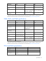
P700m, P711m, P712m, and P721m specifications
Specification
P700m
P711m
P712M
P721m
Board type
Type A, 4-port, PCIe
mezzanine board
Type A, 4-port, PCIe
mezzanine board
Type A, 4-port, PCIe
mezzanine board
Type B, 4-port, PCIe
mezzanine board
Dimensions, cm
11.3 x 10.0 x 2.0
11.3 x 10.0 x 2.0
11.3 x 10.0 x 2.0
11.3 x 10.0 x 2.0
Dimensions, in
4.5 x 4.0 x 0.8
4.5 x 4.0 x 0.8
4.5 x 4.0 x 0.8
4.5 x 4.0 x 0.8
Maximum number of
physical drives
108 external
108 external
10 internal + external 227 external
Maximum power
required (approximate)
9.30 W
14 W
14 W
14 W
RAID levels
RAID 0, 1, 1+0, and 5; RAID 0, 1, 5, 6, 50,
with battery, also RAID and 60
6
RAID 0 and 1
RAID 0, 1, 1 (ADM),
1+0, 10 (ADM), 5,
50, 6, and 60*
Battery kit option part
number
453779-001
—
—
—
Cache module
40-bit wide, 256-MiB
BBWC
72-bit wide, 512-MiB
BBWC
(64 MiB is used by the
onboard processor)
72-bit wide, 1-GiB
FBWC**
(112 MiB is used by
the onboard
processor)
40-bit wide, 256-MiB 40-bit wide, 512-MiB
BBWC
FBWC
72-bit wide, 2-GiB
FBWC†
(controller does not
operate without
cache)
I/O connection to the
system board
Grid array mezzanine
connector
Grid array mezzanine Grid array
Grid array
connector
mezzanine connector mezzanine connector
* RAID levels when using the 2-GiB FBWC. When using the 512-MiB FBWC, RAID levels are dependent on the attached
arrays.
** SAAP 1.0. License key is standard.
† SAAP 2.0. License key is standard.
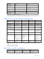
P800, P812, and P822 specifications
Specification
P800
P812
P822
Board type
Full-size, PCIe stand-up
board
Full-size, PCIe stand-up
board
Full-height, 1/2 length, PCIe
stand-up board
Specifications
35
Specification
P800
P812
P822
Dimensions, cm*
31.1 x 11.1 x 1.2
31.1 x 11.1 x 1.2
16.8 x 11.1 x 1.8
Dimensions, in*
12.3 x 4.4 x 0.5
12.3 x 4.4 x 0.5
6.6 x 4.4 x 0.7
Maximum number of
physical drives
108 (internal + external)
108 (internal + external)
227† (internal + external)
Maximum power
required (approximate)
25 W
29 W**
31 W**
RAID levels
RAID 0, 1, 1+0, and 5
RAID 0, 1, 1+0, 5, and 50 RAID 0, 1, 1 (ADM), 1+0,
10 (ADM) 5, 50, 6 and 60
Battery kit option part
number
398648-001
—
Cache module
72-bit wide, 512-MiB
BBWC
PCIe x8 edge connector
72-bit wide, 1-GiB FBWC 72-bit wide, 2-GiB FBWC
I/O connection to the
system board
PCIe 2.0 x8 edge
connector
—
PCIe 3.0 x8 edge connector
*These dimensions exclude the board bracket.
**This controller is for use on qualified systems that support power requirements above 25 W.
†
To install SLES 11 SP2, you must reduce the number of attached hard drives to less than 200 prior to installing the
operating system. After installing SLES11 SP2, download and install the latest Smart Array hpsa driver from the HP
website (http://www.hp.com/go/support) or by using SPP, and then shut down the server. You can now reattach up to
277 hard drives and boot your server to run the SLES 11 SP2 operating system.
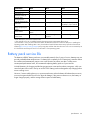
Battery pack service life
The batteries in BBWC battery packs are a consumable material. After 3 years of service, batteries may not
provide predictable data retention times. If a battery fails completely, the HP Smart Array controller detects
this condition and automatically restricts write cache functions to protect user data. To help ensure
uninterrupted performance levels, HP recommends replacing battery packs at 3-year intervals.
In NiMH batteries, the charging and discharging processes create and recombine inert gases, which can
cause the button cell to swell in size by as much as 20%. Battery packs are designed to stop charging before
excess swelling occurs.
However, if excess swelling does occur, a pressure mechanism within the button cell releases these non-toxic,
non-corrosive gases before the cell incurs physical damage. If this pressure release occurs, the battery no
longer charges properly, and the storage solution reports a failed battery.
Specifications
36
Installation and configuration
Procedures for controllers in a server
To install a stand-up controller in a server, choose one of the following procedures:
•
Installing a stand-up controller in an unconfigured server (on page 37)
•
Installing a stand-up controller in a previously configured server (on page 38)
Installing a stand-up controller in an unconfigured server
Unless the user chooses a different configuration option, new HP ProLiant servers autoconfigure when
powered up for the first time. For more information about the autoconfiguration process, see the
server-specific user guide or the HP ROM-Based Setup Utility User Guide. These guides are available on the
product Documentation CD.
IMPORTANT: Do not power up the server until the hardware configuration is satisfactory, as
described in the procedure given in this section.
To install the controller in an unconfigured server:
1.
Install the controller hardware ("Installing the controller board" on page 38). For server-specific
procedures, see the server user guide.
2.
If the controller supports external storage, connect external storage devices to the controller.
3.
Install physical drives, as needed.
The number of drives connected to the controller determines the RAID level if the server autoconfigures
at powers up, unless the user chooses a different configuration option. For more information, see the
server-specific user guide or the HP ROM-Based Setup Utility User Guide.
4.
Power up the external storage devices.
5.
Power up the server. Unless the user chooses a different configuration option, the autoconfiguration
process runs.
6.
Verify the server firmware is the latest revision. If necessary, update the server firmware ("Updating
firmware" on page 45).
7.
Verify the controller firmware is the latest revision. If necessary, update the controller firmware
("Updating firmware" on page 45).
8.
Verify the drive firmware is the latest revision. If necessary, update the drive firmware ("Updating
firmware" on page 45).
9.
Install the operating system and device drivers ("Installing device drivers" on page 45). Instructions are
provided with the CD that is supplied in the controller kit.
10.
(Optional) Create additional logical drives ("Configuration tools" on page 43).
The server is now ready for use.
Installation and configuration
37
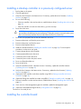
Installing a stand-up controller in a previously configured server
1.
Back up data on the system.
2.
Close all applications.
3.
Verify the server firmware is the latest revision. If necessary, update the server firmware ("Updating
firmware" on page 45).
4.
Do one of the following:
5.
o
If the new controller is the new boot device, install the device drivers ("Installing device drivers" on
page 45).
o
If the new controller is not the new boot device, go to the next step.
Power down the server.
CAUTION: In systems that use external data storage, be sure that the server is the first unit to be
powered down and the last to be powered back up. Taking this precaution ensures that the system
does not erroneously mark the drives as failed when the server is powered up.
6.
Power down all peripheral devices that are attached to the server.
7.
Disconnect the power cord from the power source.
8.
Disconnect the power cord from the server.
9.
Disconnect all peripheral devices.
10.
Install the controller hardware ("Installing the controller board" on page 38). For server-specific
procedures, see the server user guide.
11.
Connect storage devices to the controller.
12.
Connect peripheral devices to the server.
13.
Connect the power cord to the server.
14.
Connect the power cord to the power source.
15.
Power up all peripheral devices.
16.
Power up the server.
17.
Verify the controller firmware is the latest revision. If necessary, update the controller firmware
("Updating firmware" on page 45).
18.
Verify the drive firmware is the latest revision. If necessary, update the drive firmware ("Updating
firmware" on page 45).
19.
(Optional) Set this controller as the boot controller using ORCA ("Setting a controller as the boot
controller" on page 43).
20.
(Optional) Change the controller boot order using RBSU ("Setting the controller order" on page 44).
21.
If the new controller is not the new boot device, install the device drivers ("Installing device drivers" on
page 45).
22.
If new versions of the Management Agents are available, update the Management Agents.
23.
(Optional) Create additional logical drives ("Configuration tools" on page 43).
The server is now ready for use.
Installing the controller board
Installation and configuration
38
WARNING: To reduce the risk of personal injury or damage to the equipment, consult the safety
information and user documentation provided with the server before attempting the installation.
Some servers contain high energy, high circuits, moving parts (such as fan blades), or any
combination of these hazards, that may be exposed if covers and access panels are removed
while the product is powered. These products are intended to be serviced only by qualified
personnel who have been trained to deal with these hazards. Do not remove enclosures or
attempt to bypass any interlocks that may be provided for the purpose of guarding against these
hazardous conditions.
1.
Remove or open the access panel.
WARNING: To reduce the risk of personal injury from hot surfaces, allow the drives and the
internal system components to cool before touching them.
2.
Select an available x8 or larger PCIe expansion slot.
A x8 physical size slot is required, even though the slot may run at a x4 or x1 speed.
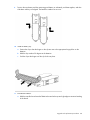
3.
Remove the slot cover. Save the retaining screw, if one is present.
4.
Install the cache module, as needed.
For some controllers, if the cache module is absent, the controller does not function.
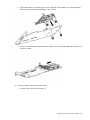
5.
Slide the controller board along the slot alignment guide, if one is present, and then press the board
firmly into the expansion slot so that the contacts on the board edge are seated properly in the slot.
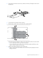
6.
Secure the controller board in place with the retaining screw. If the slot alignment guide has a latch
(near the rear of the board), close the latch.
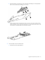
7.
Connect internal storage devices to the controller, if necessary. For more information, see "Connecting
internal storage (on page 39)."
8.
Close or install the access panel, and then secure it with thumbscrews, if any are present.
CAUTION: Do not operate the server for long periods with the access panel open or removed.
Operating the server in this manner results in improper airflow and improper cooling that can
lead to thermal damage.
Connecting internal storage
1.
Power down the server.
2.
Install drives, if necessary. For drive requirements when configuring arrays, see "Array configuration
tools (on page 44)."
The server and controller may support different types of drives. However, all drives grouped in a logical
drive must meet the following criteria:
o
They must be either SAS or SATA.
o
They must be either all hard drives or all solid state drives.
o
For the most efficient use of drive space, the drives must have comparable capacity.
For more information about drive installation, see the following resources:
3.
o
Drive procedures (on page 79)
o
Server documentation
o
Drive documentation
Use the internal SAS cable provided with the server to connect the controller to the drives:
Installation and configuration
39
4.
o
If the drives are hot-plug capable, connect the internal connector of the controller to the SAS
connector on the hot-plug drive cage.
o
If the drives are not hot-plug capable, connect the internal connector of the controller to the
non-hot-plug drives.
Close or install the access panel, and secure it with thumbscrews, if any are present.
CAUTION: Do not operate the server for long periods with the access panel open or removed.
Operating the server in this manner results in improper airflow and improper cooling that can
lead to thermal damage.
5.
Power up the server.
SAS cable part numbers
To order additional cables, use the option kit part number.
Approximate cable
length
Type of cable
Option kit part
number
Cable assembly
number
1 m (3 ft)
Mini-SAS 4x to standard SAS 4x
419570-B21
408908-002
2 m (6 ft)
Mini-SAS 4x to Mini SAS 4x
407339-B21
407344-003
—
Mini-SAS 4x to standard SAS 4x
419571-B21
408908-003
4 m (13 ft)
Mini-SAS 4x to Mini SAS 4x
432238-B21
407344-004
—
Mini-SAS 4x to standard SAS 4x
419572-B21
408908-004
6 m (20 ft)
Mini-SAS 4x to Mini SAS 4x
432239-B21
407344-005
—
Mini-SAS 4x to standard SAS 4x
419573-B21
408908-005
Procedures for controllers in a server blade
To install a mezzanine controller in a server blade, choose one of the following procedures:
•
Installing a mezzanine controller in an unconfigured server blade (on page 40)
•
Installing a mezzanine controller in a previously configured server blade (on page 41)
Installing a mezzanine controller in an unconfigured server blade
Unless the user chooses a different configuration option, new HP ProLiant server blades autoconfigure when
powered up for the first time. For more information about the autoconfiguration process, see the server blade
user guide or the HP ROM-Based Setup Utility User Guide. These guides are available on the product
Documentation CD.
IMPORTANT: Do not power up the server until the hardware configuration is satisfactory, as
described in the procedure given in this section.
To install the controller in an unconfigured server blade:
1.
Remove the server blade access panel.
2.
Do one of the following:
o
For the HP Smart Array P712m Controller, install the optional cache module, if available.
Installation and configuration
40
o
For all other controllers, install the cache module. If the cache module is absent, these controllers do
not function.
3.
Install the controller in the server blade ("Installing the mezzanine controller board" on page 42). For
server blade-specific procedures, see the server blade user guide.
4.
Install the access panel.
5.
Install an HP 3Gb or 6Gb SAS Switch in the enclosure.
6.
Connect a drive enclosure to the switch.
7.
Install physical drives in the drive enclosure, as needed.
The number of drives connected to the switch determines the RAID level that is autoconfigured when the
server blade powers up, unless the user chooses a different configuration option. For more information,
see the server-specific user guide or the HP ROM-Based Setup Utility User Guide.
8.
Create and assign drive bay or port zoning groups with HP Virtual SAS Manager software. For more
information, see the switch documentation.
9.
Install the server blade in the server blade enclosure.
By default, the server blade powers up upon insertion. If necessary, power up the server blade
manually. Unless the user chooses a different configuration option, the autoconfiguration process runs.
10.
Verify the server blade firmware is the latest revision. If necessary, update the server firmware
("Updating firmware" on page 45).
11.
Verify the controller firmware is the latest revision. If necessary, update the controller firmware
("Updating firmware" on page 45).
12.
Verify the drive firmware is the latest revision. If necessary, update the drive firmware ("Updating
firmware" on page 45).
13.
Install the operating system and device drivers ("Installing device drivers" on page 45). Instructions are
provided with the CD that is supplied in the controller kit.
14.
(Optional) Create additional logical drives ("Configuration tools" on page 43).
The server blade is now ready for use.
Installing a mezzanine controller in a previously configured server
blade
1.
Back up data on the system.
2.
Close all applications.
3.
Verify the server blade firmware is the latest revision. If necessary, update the server blade firmware
("Updating firmware" on page 45).
4.
Do one of the following:
5.
o
If the new controller is the new boot device, install the device drivers ("Installing device drivers" on
page 45).
o
If the new controller is not the new boot device, go to the next step.
Power down the server blade.
CAUTION: In systems that use external data storage, be sure that the server is the first unit to be
powered down and the last to be powered back up. Taking this precaution ensures that the system
does not erroneously mark the drives as failed when the server is powered up.
Installation and configuration
41
6.
Remove the server blade from the enclosure.
7.
Remove the server blade access panel.
8.
Do one of the following:
o
For the HP Smart Array P712m Controller, install the optional cache module, if available.
o
For all other controllers, install the cache module. If the cache module is absent, these controllers do
not function.
9.
Install the controller in the server blade ("Installing the mezzanine controller board" on page 42). For
server blade-specific procedures, see the server blade user guide.
10.
Install the access panel.
11.
Install an HP 3Gb or 6Gb SAS Switch in the enclosure.
12.
Connect a drive enclosure to the switch.
13.
Install physical drives in the drive enclosure, as needed.
The number of drives connected to the switch determines the RAID level that is autoconfigured when the
server blade powers up, unless the user chooses a different configuration option. For more information,
see the server-specific user guide or the HP ROM-Based Setup Utility User Guide.
14.
Create and assign drive bay or port zoning groups with HP Virtual SAS Manager software. For more
information, see the switch documentation.
15.
Install the server blade in the enclosure.
By default, the server blade powers up upon insertion. If necessary, power up the server blade
manually. Unless the user chooses a different configuration option, the autoconfiguration process runs.
16.
Verify the controller firmware is the latest revision. If necessary, update the controller firmware
("Updating firmware" on page 45).
17.
Verify the drive firmware is the latest revision. If necessary, update the drive firmware ("Updating
firmware" on page 45).
18.
(Optional) Set this controller as the boot controller using ORCA ("Setting a controller as the boot
controller" on page 43).
19.
(Optional) Change the controller boot order using RBSU ("Setting the controller order" on page 44).
20.
If the new controller is not the new boot device, install the device drivers ("Installing device drivers" on
page 45).
21.
If new versions of the Management Agents are available, update the Management Agents.
The server blade is now ready for use.
Installing the mezzanine controller board
WARNING: To reduce the risk of personal injury or damage to the equipment, consult the safety
information and user documentation provided with the server before attempting the installation.
Some servers contain high energy, high circuits, moving parts (such as fan blades), or any
combination of these hazards, that may be exposed if covers and access panels are removed
while the product is powered. These products are intended to be serviced only by qualified
personnel who have been trained to deal with these hazards. Do not remove enclosures or
attempt to bypass any interlocks that may be provided for the purpose of guarding against these
hazardous conditions.
1.
Remove the server blade access panel.
Installation and configuration
42
WARNING: To reduce the risk of personal injury from hot surfaces, allow the drives and the
internal system components to cool before touching them.
2.
Select an available mezzanine connector on the system board.
For more information, see "Supported servers and server blades (on page 31)."
3.
Remove the connector cover, and then save it for future use.
4.
Insert the controller into the connector.
5.
Tighten the three spring-loaded captive screws at the corners of the controller.
6.
Install the access panel.
CAUTION: Do not operate the server for long periods with the access panel open or removed.
Operating the server in this manner results in improper airflow and improper cooling that can
lead to thermal damage.
7.
Install the server blade in the enclosure.
Configuration tools
Option ROM Configuration for Arrays
Before installing an operating system, you can use the ORCA utility to create the first logical drive, assign
RAID levels, and establish online spare configurations.
The utility also provides support for the following functions:
•
Reconfiguring one or more logical drives
•
Viewing the current logical drive configuration
•
Deleting a logical drive configuration
•
Setting the controller to be the boot controller
•
Selecting the boot volume
If you do not use the utility, ORCA will default to the standard configuration.
For more information regarding the default configurations that ORCA uses, see the HP ROM-Based Setup
Utility User Guide on the Documentation CD or the HP website
(http://www.hp.com/go/ilomgmtengine/docs).
Setting a controller as the boot controller
Use the following procedure to set a controller as the boot controller. To adjust the boot order settings for
other controllers in the system, use RBSU ("Setting the controller order" on page 44).
1.
Confirm that the controller is connected to a logical drive. (If it is not, it cannot be set as the boot
controller.)
2.
Perform a normal system shutdown.
3.
Restart the server.
POST runs, and all controllers in the server are initialized one at a time in the current boot order
sequence. If a controller is connected to one or more drives, an ORCA prompt message appears during
the initialization process for that controller.
Installation and configuration
43
As soon as you see the ORCA prompt for the controller that you want to set as the boot controller,
continue with the next step.
4.
Press the F8 key.
The ORCA main menu appears. If the controller is configured with a logical drive, one of the menu
options is to set the controller as the boot controller.
5.
Select the appropriate menu option, and follow any subsequent on-screen instructions. If prompted to
save the settings, do so.
6.
(Optional) To configure or reconfigure an array on this controller, you can use ORCA. For more
information, see the Configuring Arrays on HP Smart Array Controllers Reference Guide. This guide is
available on the Documentation CD that is provided in the controller kit.
To configure an array at a later time or to use a different utility to configure the array, exit ORCA, and
then restart the server for the new boot controller setting to take effect.
ROM-Based Setup Utility
RBSU is a ROM-based configuration utility that allows you to modify server configuration settings. RBSU is
machine-specific and customized for each type of server. RBSU facilitates a wide range of configuration
functions, including displaying system information, selecting the operating system, and configuring system
devices and options.
If RBSU is supported by the server, access the utility by pressing the F9 key when prompted during the boot
process. Refer to the HP ROM-Based Setup Utility User Guide or to the server documentation.
Setting the controller order
1.
Power up the server.
The server runs the POST sequence and briefly displays an RBSU prompt.
2.
At the prompt, press the F9 key to start RBSU.
3.
Follow the on-screen instructions to set the boot order for the different controllers in the system.
4.
Save the settings.
5.
Exit from the utility.
For more information about using RBSU, refer to the HP ROM-Based Setup Utility User Guide or the server
setup and installation guide. These documents are both available on the Documentation CD supplied in the
server kit.
Array configuration tools
To configure an array on an HP Smart Array controller, three utilities are available:
•
HP Array Configuration Utility (ACU)—An advanced utility that enables you to perform many complex
configuration tasks
•
Option ROM Configuration for Arrays (ORCA)—A simple utility used mainly to configure the first logical
drive in a new server before the operating system is loaded
•
HP Online Array Configuration Utility for NetWare (CPQONLIN)—A customized version of ACU for
online configuration of servers that use Novell NetWare
Installation and configuration
44
For more information about the features of these utilities and for instructions for using the utilities, see the
Configuring Arrays on HP Smart Array Controllers Reference Guide. This guide is available on the
Documentation CD that is provided in the controller kit.
Whichever utility you use, remember the following factors when you build an array:
•
All drives grouped in a logical drive must be of the same type (for example, either all SAS or all SATA
and either all hard drives or all solid state drives).
•
For the most efficient use of drive space, all drives within an array should have approximately the same
capacity. Each configuration utility treats every physical drive in an array as if it has the same capacity
as the smallest drive in the array. Any excess capacity of a particular drive cannot be used in the array
and so is unavailable for data storage.
•
The more physical drives that there are in an array, the greater the probability that the array will
experience a drive failure during any given period.
•
To guard against the data loss that occurs when a drive fails, configure all logical drives in an array with
a suitable fault-tolerance (RAID) method.
System maintenance tools
Updating firmware
Firmware update methods changed with the introduction of the ProLiant Gen8 servers. Use the appropriate
information to locate and install firmware updates.
For Gen8 servers and server blades
Server and controller firmware should be updated before using the controller for the first time, unless any
installed software or components require an older version. For system software and firmware updates,
download the SPP from the HP website (http://www.hp.com/go/spp).
For G7 and earlier servers and server blades
To update the firmware on the server, controller, or drives, use Smart Components. These components are
available on the Firmware Maintenance CD. The most recent version of a particular component is available
on the HP support website (http://www.hp.com/support). When prompted for product information, enter
the appropriate server model name.
1.
Find the most recent version of the component that you require. Components for controller firmware
updates are available in offline and online formats.
2.
Follow the instructions for installing the component on the server. The instructions are provided on the
CD and the same Web page as the component.
3.
Follow the additional instructions that describe how to use the component to flash the ROM. The
instructions are provided with each component.
For more information about updating the firmware, see the HP ProLiant Storage Firmware Maintenance User
Guide (for controller and drive firmware) or the HP Online ROM Flash User Guide (for server firmware).
Installing device drivers
IMPORTANT: Always perform a backup before installing or updating device drivers.
Installation and configuration
45
HP now distributes drivers and other support software for servers and server blades through Service Pack for
ProLiant, or SPP, which you can download from the HP website (http://www.hp.com/go/spp/download).
Be sure to use the latest SPP version for the server or server blade.
If you installed an OS by using the Intelligent Provisioning software, its Configure and Install feature may
have provided the latest driver support.
To directly locate the OS drivers for a particular server, enter the following web address into the browser:
http://www.hp.com/support/<servername>
In place of <servername>, enter the server name.
For example:
http://www.hp.com/support/dl360g6
Installing Management Agents
If you use the Assisted Installation path feature of the Intelligent Provisioning software to install the operating
system on a new server, the Management Agents are automatically installed at the same time.
You can update the Management Agents by using the latest versions of the agents provided in the Intelligent
Provisioning software.
Diagnostic tools
To troubleshoot array problems and generate feedback about arrays, use the following diagnostic tools:
•
ACU
ACU is available on the SmartStart CD in the controller kit for ProLiant G7 and earlier server
generations. For ProLiant Gen8 servers, ACU is embedded in the system, available during boot with the
F5 key. ACU, and other system software, is also available for download in the SPP from the HP website
(http://www.hp.com/go/spp).
For more information about ACU, see the Configuring Arrays on HP Smart Array Controllers Reference
Guide on the Documentation CD that ships with the controller or on the HP website
(http://www.hp.com/support/CASAC_RG_en). For more information about error messages, see the
appropriate troubleshooting guide for your product.
•
ADU
ADU is available on the HP website (http://www.hp.com/support). When prompted for product
information, enter the server model name. For more information about the meanings of the various ADU
error messages, see the appropriate troubleshooting guide for your product.
•
Event Notification Service
This utility reports array events to the server IML and the Microsoft® Windows® system event log. You
can obtain the utility from the SmartStart CD or the HP website (http://www.hp.com/support). When
prompted for product information, enter the server model name.
•
HP Insight Diagnostics
HP Insight Diagnostics is a tool that displays information about the system hardware configuration and
performs tests on the system and its components, including drives if they are connected to Smart Array
controllers. This utility is available on the SmartStart CD and also on the HP website
(http://www.hp.com/servers/diags).
Installation and configuration
46
•
POST messages
Smart Array controllers produce diagnostic error messages (POST messages) at reboot. Many POST
messages suggest corrective actions. For more information about POST messages, see the appropriate
troubleshooting guide for your product.
Installation and configuration
47
Upgrade and replacement procedures
Replacing the battery on the P212, P410, and P411
models
CAUTION: Do not use this controller with batteries designed for other controller models, or the
controller will malfunction and you could lose data. If you use an unsupported battery for this
controller, a POST message might appear when you power up your server.
1.
Close all applications.
2.
Power down the server.
3.
Disconnect the server from the AC power source.
4.
Remove or open the access panel.
5.
Observe the BBWC status LED ("Battery pack LEDs" on page 28).
o
If the LED is blinking every two seconds, data is trapped in the cache. Restore system power, and
then repeat the previous steps in this procedure.
o
If the LED is not lit, continue with the next step.
6.
Unplug the battery cable from the old battery.
7.
Connect the battery cable to the new battery.
8.
Place the new battery at the same site in the server that the old battery occupied.
9.
Close the access panel.
Upgrade and replacement procedures
48
Replacing the FBWC module on the P410 and P411
models
CAUTION: The cache module connector does not use the industry-standard DDR3 mini-DIMM
pinout. Do not use the controller with cache modules designed for other controller models,
because the controller can malfunction and you can lose data. Also, do not transfer this cache
module to an unsupported controller model, because you can lose data.
1.
Update the controller firmware. See "Updating firmware (on page 45)."
2.
Close all applications.
3.
Power down the server.
4.
Disconnect the power cord from the AC power source.
5.
Disconnect the power cord from the server.
6.
Remove or open the access panel.
7.
If the existing cache module is connected to a capacitor pack, observe the FBWC module LEDs (on
page 26):
8.
o
If the amber LED is flashing, data is trapped in the cache. Restore system power, and restart this
procedure from step 1.
o
If the amber LED is not illuminated, remove the controller from the server, and then continue with the
next step.
Open the ejector latches on each side of the DIMM slot. Normally, the cache module is ejected from the
DIMM slot. If the module is not ejected automatically, remove the cache module.
CAUTION: When connecting or disconnecting the capacitor pack cable, the connectors on the
cache module and cable are susceptible to damage. Avoid excessive force and use caution to
avoid damage to these connectors.
Upgrade and replacement procedures
49
9.
If the cache module is connected to a capacitor pack, carefully disconnect the capacitor pack cable
from the connector on the top of the cache module.
10.
If the previous cache module was connected to a capacitor pack, carefully connect the capacitor pack
cable to the new cache module.
11.
Install the new cache module in the DIMM slot.
12.
Close the ejector latches on the DIMM slot.
13.
Install the controller.
Replacing the BBWC module on the P212, P410, and
P411 models
CAUTION: The cache module connector does not use the industry-standard DDR3 mini-DIMM
pinout. Do not use the controller with cache modules designed for other controller models,
because the controller can malfunction and you can lose data. Also, do not transfer this cache
module to an unsupported controller model, because you can lose data.
1.
Close all applications.
2.
Power down the server.
3.
Disconnect the power cord from the AC power source.
4.
Disconnect the power cord from the server.
5.
Remove or open the access panel.
6.
If the existing cache module is connected to a battery, observe the BBWC status LED ("Battery pack
LEDs" on page 28).
o
If the LED is flashing every two seconds, data is trapped in the cache. Restore system power, and
then repeat the previous steps in this procedure.
o
If the LED is not lit, remove the controller from the server, and then continue with the next step.
Upgrade and replacement procedures
50
7.
Open the ejector latches on each side of the DIMM slot. Normally, the cache module is ejected from the
DIMM slot. If the module is not ejected automatically, remove the cache module.
8.
If the cache module is connected to a battery, disconnect the battery cable from the connector on the
rear of the cache module.
9.
If the previous cache module was connected to a battery, connect the battery cable to the new cache
module.
10.
Install the new cache module in the DIMM slot.
11.
Close the ejector latches on the DIMM slot.
12.
Install the controller.
Replacing the FBWC module on the P222, P420,
P421, and P822 models
Upgrade and replacement procedures
51
CAUTION: The cache module connector does not use the industry-standard DDR3 mini-DIMM
pinout. Do not use the controller with cache modules designed for other controller models,
because the controller can malfunction and you can lose data. Also, do not transfer this cache
module to an unsupported controller model, because you can lose data.
1.
Update the controller firmware. See "Updating firmware (on page 45)."
2.
Close all applications.
3.
Power down the server.
4.
Disconnect the power cord from the AC power source.
5.
Disconnect the power cord from the server.
6.
Remove or open the access panel.
7.
If the existing cache module is connected to a capacitor pack, observe the FBWC module LEDs (on
page 26):
o
If a backup is in progress, wait for the backup to complete.
o
If the backup is complete, or if the cache has failed, remove the controller from the server, and then
continue with the next step.
8.
If access to the cache module is restricted, remove the controller.
9.
Open the ejector latches on each side of the DIMM slot. Normally, the cache module is ejected from the
DIMM slot. If the module is not ejected automatically, remove the cache module.
CAUTION: When connecting or disconnecting the capacitor pack cable, the connectors on the
cache module and cable are susceptible to damage. Avoid excessive force and use caution to
avoid damage to these connectors.
Upgrade and replacement procedures
52
10.
If the cache module is connected to a capacitor pack, carefully disconnect the capacitor pack cable
from the connector on the top of the cache module.
11.
If the previous cache module was connected to a capacitor pack, carefully connect the capacitor pack
cable to the new cache module.
12.
Install the new cache module in the DIMM slot.
13.
Close the ejector latches on the DIMM slot.
14.
If you removed the controller for access purposes, install the controller.
Installing an E500 or P400 cache battery
If you are replacing an existing E500 or P400 cache battery (instead of installing a battery where one did
not exist), use the replacement procedure ("Replacing an E500 or P400 cache battery" on page 54) instead
of this installation procedure.
WARNING: There is a risk of explosion, fire, or personal injury if the battery pack is not properly
handled. Refer to "Battery replacement notice (on page 93)" before installing or removing any
item that contains a battery pack.
1.
Close all applications, and then power down the server.
Upgrade and replacement procedures
53
2.
Plug the battery cable (supplied in the battery pack kit) into the battery pack.
3.
Install the new battery pack into the server. (The installation site depends on the server. For further
information, refer to the server-specific user guide.)
4.
Plug the other end of the battery cable into the connector on the cache module.
After installing a battery pack, you might see a POST message during reboot indicating that the array
accelerator (cache) is temporarily disabled. This behavior is normal because the new battery pack is likely to
have a low charge. You do not need to take any action because the recharge process begins automatically
when the battery pack is installed. The controller operates properly while the battery pack is recharging,
although the performance advantage of the array accelerator is absent. When the battery pack has been
charged to a predetermined level, the array accelerator is automatically enabled.
Replacing an E500 or P400 cache battery
Upgrade and replacement procedures
54
WARNING: There is a risk of explosion, fire, or personal injury if the battery pack is not properly
handled. Refer to "Battery replacement notice (on page 93)" before installing or removing any
item that contains a battery pack.
CAUTION: Do not replace a battery pack while the server is powered up. In this situation, the
loose end of the battery cable that is still connected to the cache can cause a short circuit, leading
to permanent electrical damage.
1.
Close all applications, and then power down the server.
2.
Disconnect the server from the AC power source.
3.
Remove all components that prevent access to the battery pack. For more information, see the
server-specific user guide.
4.
Observe the BBWC Status LED ("Battery pack LEDs" on page 28):
o
If the LED is flashing every two seconds, data is still trapped in the cache. Restore system power, and
then repeat the previous steps in this procedure.
o
If the LED is not lit, proceed with the next step.
5.
Disconnect the cache cable from the battery pack.
6.
Remove the battery pack from the server.
7.
Connect the cache cable to the new battery pack.
8.
Install the new battery pack into the server.
NOTE: After installing a battery pack, you might see a POST message during reboot indicating
that the array accelerator (cache) is temporarily disabled. This is normal, because the new battery
pack is likely to have a low charge. You do not need to take any action, because the recharge
process begins automatically when the battery pack is installed. The controller will operate
properly while the battery pack recharges, although the performance advantage of the array
accelerator will be absent. When the battery pack has been charged to a satisfactory level, the
array accelerator will automatically be enabled.
Replacing the E500 or P400 cache
CAUTION: The cache module connector does not use the industry-standard DDR3 mini-DIMM
pinout. Do not use the controller with cache modules designed for other controller models,
because the controller can malfunction and you can lose data. Also, do not transfer this cache
module to an unsupported controller model, because you can lose data.
1.
Close all applications, and then power down the server. This procedure flushes all data from the cache.
2.
Disconnect the power cord from the AC power source.
3.
Disconnect the power cord from the server.
4.
If the existing cache is connected to a battery, observe the BBWC Status LED ("Battery pack LEDs" on
page 28).
o
If the LED is flashing every 2 seconds, data is still trapped in the cache. Restore system power, and
then repeat the previous steps in this procedure.
Upgrade and replacement procedures
55
o
If the LED is not lit, disconnect the battery cable from the cache.
5.
Remove the controller from the server and place it on a firm, flat, nonconductive surface.
6.
Remove the existing cache from the controller by pulling at both ends of the cache module with equal
force.
7.
Install the new cache on the controller. Press firmly above each connector to ensure good electrical
contact. (If the cache is not connected properly, the controller cannot boot.)
8.
Install the controller in the server.
9.
If the previous cache was connected to a battery pack, connect the battery cable to the new cache.
Replacing the P700m cache battery
CAUTION: Electrostatic discharge can damage electronic components. Be sure you are properly
grounded before beginning this procedure.
Upgrade and replacement procedures
56
The method for replacing a battery depends on whether the battery case is mounted on the inner wall of the
server chassis by a hook-and-loop strip or located in a drive slot.
To replace a battery case mounted on the inner wall of the server chassis:
1.
Back up all data.
2.
Close all applications.
3.
Power down the server.
4.
Remove the server from the enclosure.
5.
Remove the server access panel.
6.
Remove the battery case from the chassis wall.
7.
Disconnect the cable from the battery.
8.
Connect the battery cable to the replacement battery.
9.
Mount the battery case on the chassis wall.
10.
Close the server access panel.
11.
Reinstall the server in the enclosure.
After installing a battery pack, you might see a POST message during reboot indicating that the array
accelerator (cache) is disabled temporarily. This behavior is normal because the new battery pack is likely to
have a low charge.
The controller operates properly while the battery pack is recharging, although the performance advantage
of the array accelerator is absent. You do not need to take any action because the recharge process begins
automatically when the battery pack is installed. When the battery pack has been charged to a
predetermined level, the array accelerator is enabled automatically.
To replace a battery case located in a drive slot:
1.
Back up all data.
2.
Close all applications.
3.
Power down the server.
4.
Remove the server from the enclosure.
5.
Remove the server access panel.
6.
Remove the battery case from the drive slot.
7.
Disconnect the battery cable.
8.
Invert the battery case.
Upgrade and replacement procedures
57
9.
Pull the right hand portion of the battery case away from the battery pack, and simultaneously rotate the
battery pack out of the opening.
10.
Position the replacement battery pack in the opening in the battery case as shown. The upper left edge
of the battery pack is under the flanges on the pillars at the left edge of the opening, and the right side
of the battery pack rests on the right pillars.
Upgrade and replacement procedures
58
11.
Pull the right-hand portion of the battery case away from the battery pack, and simultaneously rotate the
battery pack into the opening.
12.
Connect the battery cable to the battery pack and the cache. Route the battery cable so that the cache
and battery pack can be removed together. (If you need to remove the cache to transfer data, the
battery pack must remain connected to it so that the data is preserved.)
13.
Insert the battery case into the drive slot.
14.
Close the server access panel.
15.
Install the server in the enclosure.
After installing a battery pack, you might see a POST message during reboot indicating that the array
accelerator (cache) is disabled temporarily. This behavior is normal because the new battery pack is likely to
have a low charge.
The controller operates properly while the battery pack is recharging, although the performance advantage
of the array accelerator is absent. You do not need to take any action because the recharge process begins
automatically when the battery pack is installed. When the battery pack has been charged to a
predetermined level, the array accelerator is enabled automatically.
Removing a P711m capacitor pack
1.
Close all applications, and then power down the server blade. This method flushes all data from the
cache module.
2.
Observe the FBWC module LEDs (on page 26):
3.
o
If the green LED is off and the amber LED is on, the controller is transferring data from DDR memory
to flash memory. Wait for data transfer to complete (about 60 seconds), and then proceed with the
next step.
o
If the amber LED is off, then proceed with the next step.
Remove the controller from the server. See the documentation that ships with the server blade.
CAUTION: When connecting or disconnecting the capacitor pack cable, the connectors on the
cache module and cable are susceptible to damage. Avoid excessive force and use caution to
avoid damage to these connectors.
Upgrade and replacement procedures
59
4.
Remove the capacitor pack:
a. Lift the capacitor pack away from the bracket.
b. Disconnect the capacitor pack cable from the cache module.
Replacing a P711m cache module
CAUTION: To prevent damage to electrical components, properly ground the server before
beginning any installation, removal, or replacement procedure. Improper grounding can cause
electrostatic discharge.
1.
Close all applications, and then power down the server blade. This method flushes all data from the
cache module.
2.
Observe the FBWC module LEDs (on page 26):
3.
o
If the green LED is off and the amber LED is on, the controller is transferring data from DDR memory
to flash memory. Wait for data transfer to complete (about 60 seconds), and then proceed with the
next step.
o
If the amber LED is off, then proceed with the next step.
Remove the controller from the server. See the documentation that ships with the server blade.
Upgrade and replacement procedures
60
CAUTION: When connecting or disconnecting the capacitor pack cable, the connectors on the
cache module and cable are susceptible to damage. Avoid excessive force and use caution to
avoid damage to these connectors.
4.
Remove the capacitor pack:
a. Lift the capacitor pack away from the bracket.
b. Disconnect the capacitor pack cable from the cache module.
Upgrade and replacement procedures
61
5.
Remove the original cache module.
CAUTION: The cache module connector does not use the industry-standard DDR3 mini-DIMM
pinout. Do not use the controller with cache modules designed for other controller models,
because the controller can malfunction and you can lose data. Also, do not transfer this cache
module to an unsupported controller model, because you can lose data.
6.
Install the replacement or upgrade cache module.
Upgrade and replacement procedures
62
7.
Install the capacitor pack onto the bracket, leaving sufficient room to connect the capacitor pack cable.
CAUTION: When connecting or disconnecting the capacitor pack cable, the connectors on the
cache module and cable are susceptible to damage. Avoid excessive force and use caution to
avoid damage to these connectors.
8.
Connect the capacitor pack cable to the cache module.
9.
Install the controller in the server blade.
After installing a capacitor pack, you might see a POST message during reboot indicating that the array
accelerator (cache module) is disabled temporarily. This behavior is normal because the new capacitor pack
is likely to have a low charge. You do not need to take any action, because the recharge process begins
automatically after the capacitor pack is installed and the server is powered. The controller operates properly
while the capacitor pack recharges, although the performance advantage of the array accelerator is absent.
When the capacitor pack has been charged to a satisfactory level, the controller enables the array
accelerator automatically.
Replacing a P712m cache module
Upgrade and replacement procedures
63
CAUTION: The cache module connector does not use the industry-standard DDR3 mini-DIMM
pinout. Do not use the controller with cache modules designed for other controller models,
because the controller can malfunction and you can lose data. Also, do not transfer this cache
module to an unsupported controller model, because you can lose data.
1.
Close all applications, and then power down the server blade.
2.
Remove or open the access panel.
3.
Open the ejector latches on each side of the DIMM slot. Normally, the cache module is ejected from the
DIMM slot. If the module is not ejected automatically, remove the cache module.
4.
Install the new cache module in the DIMM slot.
5.
Close the ejector latches on the DIMM slot.
6.
Install the controller.
Replacing the FBWC module on the P721m
CAUTION: The cache module connector does not use the industry-standard DDR3 mini-DIMM
pinout. Do not use the controller with cache modules designed for other controller models,
because the controller can malfunction and you can lose data. Also, do not transfer this cache
module to an unsupported controller model, because you can lose data.
1.
Update the controller firmware. See "Updating firmware (on page 45)."
2.
Close all applications, and then power down the server blade.
3.
Remove or open the access panel.
4.
If the existing cache module is connected to a capacitor pack, observe the FBWC module LEDs (on
page 26):
5.
o
If a backup is in progress, wait for the backup to complete.
o
If the backup is complete, or if the cache has failed, remove the controller from the server, and then
continue with the next step.
If access to the cache module is restricted, remove the controller.
Upgrade and replacement procedures
64
6.
Open the ejector latches on each side of the DIMM slot. Normally, the cache module is ejected from the
DIMM slot. If the module is not ejected automatically, remove the cache module.
CAUTION: When connecting or disconnecting the capacitor pack cable, the connectors on the
cache module and cable are susceptible to damage. Avoid excessive force and use caution to
avoid damage to these connectors.
7.
If the cache module is connected to a capacitor pack, carefully disconnect the capacitor pack cable
from the connector on the top of the cache module.
8.
If the previous cache module was connected to a capacitor pack, carefully connect the capacitor pack
cable to the new cache module.
9.
Install the new cache module in the DIMM slot.
10.
Close the ejector latches on the DIMM slot.
11.
If you removed the controller for access purposes, install the controller.
Replacing a P800 cache battery
Upgrade and replacement procedures
65
CAUTION: Electrostatic discharge can damage electronic components. Be sure you are properly
grounded before beginning this procedure.
1.
Close all applications, and then power down the server. This procedure flushes all data from the cache.
2.
Observe the BBWC Status LED ("Battery pack LEDs" on page 28).
o
If the LED is blinking every 2 seconds, data is trapped in the cache. Restore system power, and then
repeat the previous steps in this procedure.
o
If the LED is not lit, proceed with the next step.
WARNING: There is a risk of explosion, fire, or personal injury if the battery pack is not properly
handled. Refer to "Battery replacement notice (on page 93)" before installing or removing any
item that contains a battery pack.
3.
Remove the controller from the server.
4.
Pull the flanges on the battery clip outward (1), and then swivel the clip 180 degrees so that it rests on
the batteries (2).
5.
Slide the batteries toward the right edge of the controller, away from the bracket.
Upgrade and replacement procedures
66
6.
While holding the battery assembly, tilt the clip until it is at about 30 degrees to the batteries, and then
push the clip in line with the clip hinges until the clip detaches from the batteries.
The rest of the procedure depends on whether you are replacing a battery or adding one.
7.
o
If you are replacing a battery, continue with the next step.
o
If you are only adding an optional third battery, go to step 9.
Separate the batteries.
a. Turn the batteries over.
b. Pull the lip on the right battery case away from the edge of the adjacent battery case (1).
c.
8.
Slide the batteries apart (2).
Dispose of the exhausted or faulty battery using environmentally approved procedures ("Battery
replacement notice" on page 93).
Upgrade and replacement procedures
67
9.
Position the new battery and the remaining good battery as indicated, push them together, and then
slide them until they are aligned. The batteries combine into one unit.
10.
Install the battery clip.
a. Position the clip so that the hinges on the clip are next to the appropriate hinge pillars on the
batteries.
b. Hold the clip at about 30 degrees to the batteries.
c.
11.
Push the clip at the hinges until the clip clicks into place.
Reinstall the batteries.
a. Hold the controller board near the DIMM socket and at the top and right edges to minimize bending
of the board.
Upgrade and replacement procedures
68
b. Position the batteries so that the pegs A on the underside of each battery are in the appropriate
holes B on the controller board and pegs C are in slots D.
c.
12.
Slide the batteries toward the board bracket until they are firmly seated against the connectors on
the cache module.
Secure the battery clip to the controller board:
a. Swivel the clip over the cache module (1).
Upgrade and replacement procedures
69
b. Push the clip firmly at both ends (2) until it clicks into place under the controller board.
13.
Reinstall the controller in the server.
After installing a battery pack, you might see a POST message during reboot indicating that the array
accelerator (cache) is temporarily disabled. This behavior is normal because the new battery pack is likely to
have a low charge. You do not need to take any action, because the recharge process begins automatically
when the battery pack is installed. The controller operates properly while the battery pack recharges,
although the performance advantage of the array accelerator is absent. When the battery pack has been
charged to a satisfactory level, the array accelerator is automatically enabled.
Replacing the P800 cache module or controller
CAUTION: Electrostatic discharge can damage electronic components. Be sure you are properly
grounded before beginning this procedure.
1.
Close all applications, and then power down the server. This procedure flushes all data from the cache.
2.
Observe the BBWC Status LED ("Battery pack LEDs" on page 28).
o
If the LED is blinking every 2 seconds, data is trapped in the cache. Restore system power, and
repeat the previous steps in this procedure.
o
If the LED is not lit, proceed with the next step.
WARNING: There is a risk of explosion, fire, or personal injury if the battery pack is not properly
handled. Refer to "Battery replacement notice (on page 93)" before installing or removing any
item that contains a battery pack.
3.
Remove the controller from the server.
Upgrade and replacement procedures
70
4.
Pull the flanges on the battery clip outward (1), and then swivel the clip 180 degrees so that it rests on
the batteries (2).
5.
Swivel the latches on the DIMM connector outward (1).
6.
Slide the battery assembly and the cache module off the controller board (2).
The procedure at this point depends on whether you are replacing the controller or the cache module.
7.
o
If you are replacing the controller, go directly to the next step.
o
If you are replacing the cache module, pull it out of the battery assembly, install the new cache
module in its place, and then go to the next step.
Install the cache module and batteries on the controller board.
a. Hold the controller board near the DIMM connector and at the top and right edges to minimize
bending of the board.
Upgrade and replacement procedures
71
b. Position the batteries so that the pegs A on the underside of each battery are in the appropriate
holes B on the controller board, and pegs C are in slots D.
c.
8.
Slide the batteries toward the board bracket until the connectors on the cache module are firmly
seated in the DIMM connector. (When the cache module is correctly seated, the gold contacts on the
cache module are completely hidden within the DIMM connector.)
Secure the battery clip to the controller board.
a. Swivel the clip over the cache module (1).
Upgrade and replacement procedures
72
b. Push the clip firmly at both ends (2) until it clicks into place under the controller board.
9.
Reinstall the controller in the server.
Replacing a P812 cache module
CAUTION: To prevent damage to electrical components, properly ground the server before
beginning any installation, removal, or replacement procedure. Improper grounding can cause
electrostatic discharge.
1.
Close all applications, and then power down the server. This method flushes all data from the cache
module.
2.
Observe the FBWC module LEDs (on page 26):
o
If the green LED is off and the amber LED is on, the controller is transferring data from DDR memory
to flash memory. Wait for data transfer to complete (about 60 seconds), and then proceed with the
next step.
o
If the amber LED is off, then proceed with the next step.
3.
Remove the controller from the server. See the documentation that ships with the server.
4.
Open the capacitor pack clip:
a. Pull the battery clip flanges outward.
Upgrade and replacement procedures
73
b. Rotate the clip 180 degrees so that it rests on top of the capacitor pack.
CAUTION: When connecting or disconnecting the capacitor pack cable, the connectors on the
cache module and cable are susceptible to damage. Avoid excessive force and use caution to
avoid damage to these connectors.
5.
Remove the capacitor pack:
a. Slide the capacitor pack 2 cm away from the cache module.
b. Disconnect the capacitor pack cable from the cache module.
c.
Lift the capacitor pack and clip from the controller.
Upgrade and replacement procedures
74
6.
Remove the original cache module.
CAUTION: The cache module connector does not use the industry-standard DDR3 mini-DIMM
pinout. Do not use the controller with cache modules designed for other controller models,
because the controller can malfunction and you can lose data. Also, do not transfer this cache
module to an unsupported controller model, because you can lose data.
7.
Install the replacement or upgrade cache module.
8.
Align the posts on the bottom of the capacitor pack with the hole and groove on the controller.
Upgrade and replacement procedures
75
9.
Lower the capacitor pack onto the controller, leaving sufficient room to connect the capacitor pack
cable.
CAUTION: When connecting or disconnecting the capacitor pack cable, the connectors on the
cache module and cable are susceptible to damage. Avoid excessive force and use caution to
avoid damage to these connectors.
10.
Connect the capacitor pack cable to the cache module.
11.
Slide the capacitor pack toward the cache module. Be sure that the edge of the cache module slides into
the groove in the capacitor pack.
12.
Secure the capacitor pack clip:
Upgrade and replacement procedures
76
a. Rotate the clip down over the cache module.
b. Firmly press both ends of the clip until they click into place beneath the controller board.
13.
Install the controller in the server.
After installing a capacitor pack, you might see a POST message during reboot indicating that the array
accelerator (cache module) is disabled temporarily. This behavior is normal because the new capacitor pack
is likely to have a low charge. You do not need to take any action, because the recharge process begins
automatically after the capacitor pack is installed and the server is powered. The controller operates properly
while the capacitor pack recharges, although the performance advantage of the array accelerator is absent.
When the capacitor pack has been charged to a satisfactory level, the controller enables the array
accelerator automatically.
Replacing a P822 cache module
CAUTION: To prevent damage to electrical components, properly ground the server before
beginning any installation, removal, or replacement procedure. Improper grounding can cause
electrostatic discharge.
1.
Close all applications, and then power down the server. This method flushes all data from the cache
module.
2.
Observe the FBWC module LEDs (on page 26):
3.
o
If the green LED is off and the amber LED is on, the controller is transferring data from DDR memory
to flash memory. Wait for data transfer to complete (about 60 seconds), and then proceed with the
next step.
o
If the amber LED is off, then proceed with the next step.
Remove the controller from the server. See the documentation that ships with the server.
Upgrade and replacement procedures
77
4.
Remove the original cache module.
CAUTION: The cache module connector does not use the industry-standard DDR3 mini-DIMM
pinout. Do not use the controller with cache modules designed for other controller models,
because the controller can malfunction and you can lose data. Also, do not transfer this cache
module to an unsupported controller model, because you can lose data.
5.
Install the replacement or upgrade cache module.
6.
Install the controller in the server.
Upgrade and replacement procedures
78
Drive procedures
Identifying the status of a legacy drive
Legacy drives are supported on ProLiant G7, and earlier, servers and server blades. Identify a legacy drive
by its carrier, shown in the following illustration.
When a drive is configured as a part of an array and connected to a powered-up controller, the drive LEDs
indicate the condition of the drive.
Item
Description
1
Fault/UID LED (amber/blue)
2
Online LED (green)
Online/activity
LED (green)
Fault/UID LED
(amber/blue)
Interpretation
On, off, or flashing Alternating amber
and blue
The drive has failed, or a predictive failure alert has been received
for this drive; it also has been selected by a management
application.
On, off, or flashing Steadily blue
The drive is operating normally, and it has been selected by a
management application.
On
Amber, flashing
regularly (1 Hz)
A predictive failure alert has been received for this drive.
Replace the drive as soon as possible.
On
Off
The drive is online, but it is not active currently.
Flashing regularly
(1 Hz)
Amber, flashing
regularly (1 Hz)
Do not remove the drive. Removing a drive may terminate the
current operation and cause data loss.
The drive is part of an array that is undergoing capacity expansion
or stripe migration, but a predictive failure alert has been received
for this drive. To minimize the risk of data loss, do not replace the
drive until the expansion or migration is complete.
Drive procedures
79
Online/activity
LED (green)
Fault/UID LED
(amber/blue)
Interpretation
Flashing regularly
(1 Hz)
Off
Do not remove the drive. Removing a drive may terminate the
current operation and cause data loss.
The drive is rebuilding, erasing, or it is part of an array that is
undergoing capacity expansion or stripe migration.
Flashing irregularly Amber, flashing
regularly (1 Hz)
The drive is active, but a predictive failure alert has been received
for this drive. Replace the drive as soon as possible.
Flashing irregularly Off
Steadily amber
Off
The drive is active, and it is operating normally.
A critical fault condition has been identified for this drive, and the
controller has placed it offline. Replace the drive as soon as
possible.
Off
Amber, flashing
regularly (1 Hz)
A predictive failure alert has been received for this drive. Replace
the drive as soon as possible.
Off
Off
The drive is offline, a spare, or not configured as part of an array.
Identifying the status of an HP SmartDrive
HP SmartDrives are the latest HP drive technology, and they are supported beginning with ProLiant Gen8
servers and server blades. The HP SmartDrive is not supported on earlier generation servers and server
blades. Identify an HP SmartDrive by its carrier, shown in the following illustration.
When a drive is configured as a part of an array and connected to a powered-up controller, the drive LEDs
indicate the condition of the drive.
Item
LED
Status
Definition
1
Locate
Solid blue
The drive is being identified by a host application.
Flashing blue
The drive carrier firmware is being updated or requires an update.
Rotating green
Drive activity
Off
No drive activity
Solid white
Do not remove the drive. Removing the drive causes one or more of
the logical drives to fail.
Off
Removing the drive does not cause a logical drive to fail.
Solid green
The drive is a member of one or more logical drives.
Flashing green
The drive is rebuilding or performing a RAID migration, stripe size
migration, capacity expansion, or logical drive extension, or is
erasing.
2
3
4
Activity ring
Do not remove
Drive status
Drive procedures
80
Item
LED
Status
Definition
Flashing
amber/green
The drive is a member of one or more logical drives and predicts
the drive will fail.
Flashing amber
The drive is not configured and predicts the drive will fail.
Solid amber
The drive has failed.
Off
The drive is not configured by a RAID controller.
The blue Locate LED is behind the release lever and is visible when illuminated.
Recognizing drive failure
If any of the following occurs, the drive has failed:
•
The fault LED illuminates.
•
When failed drives are located inside the server or storage system and the drive LEDs are not visible, the
amber LED on the front of the server or storage system illuminates. This LED also illuminates when other
problems occur such as when a fan fails, a redundant power supply fails, or the system overheats.
•
A POST message lists failed drives when the system is restarted, as long as the controller detects at least
one functional drive.
•
ACU represents failed drives with a distinctive icon.
•
HP Systems Insight Manager can detect failed drives remotely across a network. For more information
about HP Systems Insight Manager, see the documentation on the Management CD.
•
The HP System Management Homepage (SMH) indicates that a drive has failed.
•
The Event Notification Service posts an event to the server IML and the Microsoft® Windows® system
event log.
•
ADU lists all failed drives.
For additional information about diagnosing drive problems, see the HP Servers Troubleshooting Guide.
CAUTION: Sometimes, a drive that has previously been failed by the controller may seem to be
operational after the system is power-cycled or (for a hot-pluggable drive) after the drive has been
removed and reinserted. However, continued use of such marginal drives may eventually result in
data loss. Replace the marginal drive as soon as possible.
Effects of a drive failure
When a drive fails, all logical drives that are in the same array are affected. Each logical drive in an array
might be using a different fault-tolerance method, so each logical drive can be affected differently.
•
RAID 0 configurations cannot tolerate drive failure. If any physical drive in the array fails, all RAID 0
logical drives in the same array also fail.
•
RAID 1+0 configurations can tolerate multiple drive failures if no failed drives are mirrored to one
another.
•
RAID 5 configurations can tolerate one drive failure.
•
RAID 50 configurations can tolerate one failed drive in each parity group.
Drive procedures
81
•
RAID 6 configurations can tolerate two failed drives at a given time.
•
RAID 60 configurations can tolerate two failed drives in each parity group.
•
RAID 1 (ADM) and RAID 10 (ADM) configurations can tolerate multiple drive failures if no more than
two drives, mirrored to one another, fail.
Compromised fault tolerance
CAUTION: When fault tolerance is compromised, data loss can occur. However, it may be
possible to recover the data. For more information, see "Recovering from compromised fault
tolerance (on page 82)."
If more drives fail than the fault-tolerance method can manage, fault tolerance is compromised, and the
logical drive fails. If this failure occurs, the operating system rejects all requests and indicates unrecoverable
errors.
For example, fault tolerance might occur when a drive in an array fails while another drive in the array is
being rebuilt.
Compromised fault tolerance can also be caused by problems unrelated to drives. In such cases, replacing
the physical drives is not required.
Recovering from compromised fault tolerance
If fault tolerance is compromised, inserting replacement drives does not improve the condition of the logical
volume. Instead, if the screen displays unrecoverable error messages, perform the following procedure to
recover data:
1.
Power down the entire system, and then power it back up. In some cases, a marginal drive will work
again for long enough to enable you to make copies of important files.
If a 1779 POST message is displayed, press the F2 key to re-enable the logical volumes. Remember that
data loss has probably occurred and any data on the logical volume is suspect.
2.
Make copies of important data, if possible.
3.
Replace any failed drives.
4.
After you have replaced the failed drives, fault tolerance may again be compromised. If so, cycle the
power again. If the 1779 POST message is displayed:
a. Press the F2 key to re-enable the logical drives.
b. Recreate the partitions.
c.
Restore all data from backup.
To minimize the risk of data loss that is caused by compromised fault tolerance, make frequent backups of all
logical volumes.
Replacing drives
The most common reason for replacing a drive is that it has failed. However, another reason is to gradually
increase the storage capacity of the entire system ("Upgrading drive capacity" on page 86).
Drive procedures
82
If you insert a hot-pluggable drive into a drive bay while the system power is on, all disk activity in the array
pauses for 1 or 2 seconds while the new drive is initializing. When the drive is ready, data recovery to the
replacement drive begins automatically if the array is in a fault-tolerant configuration.
If you replace a drive belonging to a fault-tolerant configuration while the system power is off, a POST
message appears when the system is next powered up. This message prompts you to press the F1 key to start
automatic data recovery. If you do not enable automatic data recovery, the logical volume remains in a
ready-to-recover condition and the same POST message appears whenever the system is restarted.
Before replacing drives
•
Open Systems Insight Manager, and inspect the Error Counter window for each physical drive in the
same array to confirm that no other drives have any errors. For more information, see the Systems
Insight Manager documentation on the Management CD.
•
Be sure that the array has a current, valid backup.
•
Confirm that the replacement drive is of the same type as the degraded drive (either SAS or SATA and
either hard drive or solid state drive).
•
Use replacement drives that have a capacity equal to or larger than the capacity of the smallest drive
in the array. The controller immediately fails drives that have insufficient capacity.
In systems that use external data storage, be sure that the server is the first unit to be powered down and the
last unit to be powered up. Taking this precaution ensures that the system does not, erroneously, mark the
drives as failed when the server is powered up.
In some situations, you can replace more than one drive at a time without data loss. For example:
•
In RAID 1+0 configurations, drives are mirrored in pairs. You can replace several drives simultaneously
if they are not mirrored to other removed or failed drives.
•
In RAID 50 configurations, drives are arranged in parity groups. You can replace several drives
simultaneously, if the drives belong to different parity groups. If two drives belong to the same parity
group, replace those drives one at a time.
•
In RAID 6 configurations, you can replace any two drives simultaneously.
•
In RAID 60 configurations, drives are arranged in parity groups. You can replace several drives
simultaneously, if no more than two of the drives being replaced belong to the same parity group.
To remove more drives from an array than the fault tolerance method can support, follow the previous
guidelines for removing several drives simultaneously, and then wait until rebuild is complete (as indicated by
the drive LEDs) before removing additional drives.
However, if fault tolerance has been compromised, and you must replace more drives than the fault tolerance
method can support, delay drive replacement until after you attempt to recover the data (refer to "Recovering
from compromised fault tolerance" on page 82).
Automatic data recovery (rebuild)
When you replace a drive in an array, the controller uses the fault-tolerance information on the remaining
drives in the array to reconstruct the missing data (the data that was originally on the replaced drive) and
then write the data to the replacement drive. This process is called automatic data recovery or rebuild. If fault
tolerance is compromised, the controller cannot reconstruct the data, and the data is likely lost permanently.
Drive procedures
83
If another drive in the array fails while fault tolerance is unavailable during rebuild, a fatal system error can
occur, and all data on the array can be lost. However, failure of another drive does not always lead to a fatal
system error in the following exceptional cases:
•
Failure after activation of a spare drive
•
Failure of a drive that is not mirrored to any other failed drives (in a RAID 1+0 configuration)
•
Failure of a second drive in a RAID 50 or RAID 60 configuration if the two failed drives are in different
parity groups
•
Failure of a second drive in a RAID 6 configuration
Time required for a rebuild
The time required for a rebuild varies, depending on several factors:
•
The priority that the rebuild is given over normal I/O operations (you can change the priority setting by
using ACU)
•
The amount of I/O activity during the rebuild operation
•
The average bandwidth capability (MBps) of the drives
•
The availability of drive cache
•
The brand, model, and age of the drives
•
The amount of unused capacity on the drives
•
For RAID 5, RAID 50, RAID 6, and RAID 60, the number of drives in the array
•
The stripe size of the logical volume
CAUTION: Because data rebuild time ranges from 200 to 520 GB/h, the system could be
unprotected against drive failure for an extended period during data recovery or a drive capacity
upgrade. When possible, perform rebuild operations only during periods of minimal system
activity.
When automatic data recovery has finished, the replacement drive LED behavior changes:
•
For legacy drives, the Online/Activity LED changes from flashing steadily (1 Hz) to one of the following
states:
o
On—The drive is inactive.
o
Flashing irregularly—The drive is active.
If the Online/Activity LED on the replacement drive does not illuminate while the corresponding LEDs on
other drives in the array are active, the rebuild process has terminated abnormally. The amber Fault LED
of one or more drives might also be illuminated.
•
For HP SmartDrives, the Drive status LED changes from flashing green to solid green.
If the Drive Status LED on the replacement drive changes to flashing or solid amber, the rebuild process
has terminated abnormally.
If an abnormal termination of a rebuild occurs, identify the cause and appropriate corrective steps in
"Abnormal termination of a rebuild (on page 85)."
Drive procedures
84
Abnormal termination of a rebuild
If the activity LED on the replacement drive permanently ceases to be illuminated even while other drives in
the array are active, the rebuild process has terminated abnormally. The following table indicates the three
possible causes of abnormal termination of a rebuild.
Observation
Cause of rebuild termination
None of the drives in the array have an One of the drives in the array has
experienced an uncorrectable read error.
illuminated amber LED.
The
replacement drive has failed.
The replacement drive has an
illuminated amber LED.
One of the other drives in the array has The drive with the illuminated amber LED has
now failed.
an illuminated amber LED.
Each of these situations requires a different remedial action.
Case 1: An uncorrectable read error has occurred.
1.
Back up as much data as possible from the logical drive.
CAUTION: Do not remove the drive that has the media error. Doing so causes the logical drive
to fail.
2.
Restore data from backup. Writing data to the location of the unreadable sector often eliminates the
error.
3.
Remove and reinsert the replacement drive. This action restarts the rebuild process.
If the rebuild process still terminates abnormally:
1.
Delete and recreate the logical drive.
2.
Restore data from backup.
Case 2: The replacement drive has failed.
Verify that the replacement drive is of the correct capacity and is a supported model. If these factors are not
the cause of the problem, use a different drive as the replacement.
Case 3: Another drive in the array has failed.
A drive that has recently failed can sometimes be made temporarily operational again by cycling the server
power.
1.
Power down the server.
2.
Remove the replacement physical drive (the one undergoing a rebuild), and reinstall the drive that it is
replacing.
3.
Power up the server.
If the newly failed drive seems to be operational again:
1.
Back up any unsaved data.
2.
Remove the drive that was originally to be replaced, and reinsert the replacement physical drive. The
rebuild process automatically restarts.
3.
When the rebuild process has finished, replace the newly failed drive.
However, if the newly failed drive has not recovered:
1.
Remove the drive that was originally to be replaced, and reinsert the replacement physical drive.
2.
Replace the newly failed drive.
Drive procedures
85
3.
Restore data from backup.
Upgrading drive capacity
You can increase the storage capacity on a system, even if there are no available drive bays, by swapping
drives one at a time for higher capacity drives. This method is viable as long as a fault-tolerance method is
running.
CAUTION: Because data rebuild time ranges from 200 to 520 GB/h, the system could be
unprotected against drive failure for an extended period during data recovery or a drive capacity
upgrade. When possible, perform rebuild operations only during periods of minimal system
activity.
To upgrade drive capacity:
1.
Back up all data.
2.
Replace any drive. The data on the new drive is re-created from redundant information on the remaining
drives.
CAUTION: Do not replace any other drive until data rebuild on this drive is complete.
When data rebuild on the new drive is complete, LED behavior changes:
o
For legacy drives, the Online/Activity LED changes from flashing steadily (1 Hz) to one of the
following states:
— On—The drive is inactive.
— Flashing irregularly—The drive is active.
o
3.
For HP SmartDrives, the Drive status LED changes from flashing green to solid green.
Repeat the previous step for the other drives in the array, one at a time.
When you have replaced all drives, you can use the extra capacity to either create new logical drives or
extend existing logical drives. For more information, see the Configuring Arrays on HP Smart Array
Controllers Reference Guide on the HP website (http://www.hp.com/support/CASAC_RG_en).
Moving drives and arrays
You can move drives to other ID positions on the same array controller. You can also move a complete array
from one controller to another, even if the controllers are on different servers.
Before moving drives, you must meet the following conditions:
•
If moving the drives to a different server, be sure the new server has enough empty bays to
accommodate all the drives simultaneously.
•
The array does not have failed or missing drives.
•
No spare drive in the array is acting as a replacement for a failed drive.
•
The controller is not performing capacity expansion, capacity extension, or RAID or stripe size
migration.
•
The controller is using the latest firmware version.
•
The server is powered down.
Drive procedures
86
Before you move an array to another controller, you must meet the following conditions:
CAUTION: If the number of physical or logical drives exceeds the limit for the controller model
and firmware version, then the controller may recognize an unpredictable subset of the drives,
possibly resulting in failed arrays and data loss.
•
If the other controller is connected already to one or more arrays of configured logical drives, the total
number of logical drives on the controller after the drives have been moved must not exceed the number
of logical drives that the controller supports. This number depends on the controller model and on the
controller firmware version.
•
The total number of physical drives on the other controller after the drives have been moved must not
exceed the maximum number of supported physical drives for that controller model and firmware
version.
•
All drives in the array must be moved at the same time.
When all the conditions have been met, move the drives:
1.
Back up all data before removing any drives or changing configuration. This step is required if you are
moving data-containing drives from a controller that does not have a cache module.
2.
Power down the system.
3.
Move the drives.
4.
Power up the system.
5.
Observe the POST messages:
6.
o
If a 1785 POST message appears, the drive array did not configure properly. Continue with step 6.
o
If a 1724 or 1727 POST message appears, drive positions were changed successfully and the
configuration was updated. Continue with step 7.
If the array did not configure properly, do the following:
a. Power down the system immediately to prevent data loss.
b. Return the drives to their original locations.
c.
7.
Restore the data from backup, if necessary.
Verify the new drive configuration by running ORCA or ACU ("Configuration tools" on page 43).
Adding drives
You can add drives to a system at any time, if you do not exceed the maximum number of drives that the
controller supports. You can then either build a new array from the added drives or use the extra storage
capacity to expand the capacity of an existing array.
If the drives that you intend to add to the system are already configured into logical drives, you must meet
certain conditions before adding drives to the system. For more information, see "Moving drives and arrays
(on page 86)." When you have successfully added the drives, reset the server so that the controller can
recognize the logical drives.
To perform an array capacity expansion, use ACU. If the system uses hot-pluggable drives and ACU runs in
the same environment as the normal server applications, you can expand array capacity without shutting
down the operating system. For more information, see the Configuring Arrays on HP Smart Array Controllers
Reference Guide on the HP website (http://www.hp.com/support/CASAC_RG_en).
Drive procedures
87
The expansion process is illustrated in the following figure, in which the original array (containing data) is
shown with a dashed border, and the newly added drives (containing no data) are shown unshaded. The
array controller adds the new drives to the array and redistributes the original logical drives over the
enlarged array one logical drive at a time. This process liberates some storage capacity on each physical
drive in the array. Each logical drive keeps the same fault-tolerance method in the enlarged array that it had
in the smaller array.
When the expansion process has finished, you can use the liberated storage capacity on the enlarged array
to create new logical drives. Alternatively, you can use ACU to enlarge (extend) one of the original logical
drives.
Drive procedures
88
Electrostatic discharge
Preventing electrostatic discharge
To prevent damaging the system, be aware of the precautions you need to follow when setting up the system
or handling parts. A discharge of static electricity from a finger or other conductor may damage system
boards or other static-sensitive devices. This type of damage may reduce the life expectancy of the device.
To prevent electrostatic damage:
•
Avoid hand contact by transporting and storing products in static-safe containers.
•
Keep electrostatic-sensitive parts in their containers until they arrive at static-free workstations.
•
Place parts on a grounded surface before removing them from their containers.
•
Avoid touching pins, leads, or circuitry.
•
Always be properly grounded when touching a static-sensitive component or assembly.
Grounding methods to prevent electrostatic discharge
Several methods are used for grounding. Use one or more of the following methods when handling or
installing electrostatic-sensitive parts:
•
Use a wrist strap connected by a ground cord to a grounded workstation or computer chassis. Wrist
straps are flexible straps with a minimum of 1 megohm ±10 percent resistance in the ground cords. To
provide proper ground, wear the strap snug against the skin.
•
Use heel straps, toe straps, or boot straps at standing workstations. Wear the straps on both feet when
standing on conductive floors or dissipating floor mats.
•
Use conductive field service tools.
•
Use a portable field service kit with a folding static-dissipating work mat.
If you do not have any of the suggested equipment for proper grounding, have an authorized reseller install
the part.
For more information on static electricity or assistance with product installation, contact an authorized
reseller.
Electrostatic discharge
89
Regulatory compliance notices
Federal Communications Commission notice
Part 15 of the Federal Communications Commission (FCC) Rules and Regulations has established Radio
Frequency (RF) emission limits to provide an interference-free radio frequency spectrum. Many electronic
devices, including computers, generate RF energy incidental to their intended function and are, therefore,
covered by these rules. These rules place computers and related peripheral devices into two classes, A and
B, depending upon their intended installation. Class A devices are those that may reasonably be expected
to be installed in a business or commercial environment. Class B devices are those that may reasonably be
expected to be installed in a residential environment (for example, personal computers). The FCC requires
devices in both classes to bear a label indicating the interference potential of the device as well as additional
operating instructions for the user.
FCC rating label
The FCC rating label on the device shows the classification (A or B) of the equipment. Class B devices have
an FCC logo or ID on the label. Class A devices do not have an FCC logo or ID on the label. After you
determine the class of the device, refer to the corresponding statement.
FCC Notice, Class A Equipment
This equipment has been tested and found to comply with the limits for a Class A digital device, pursuant to
Part 15 of the FCC Rules. These limits are designed to provide reasonable protection against harmful
interference when the equipment is operated in a commercial environment. This equipment generates, uses,
and can radiate radio frequency energy and, if not installed and used in accordance with the instructions,
may cause harmful interference to radio communications. Operation of this equipment in a residential area
is likely to cause harmful interference, in which case the user will be required to correct the interference at
personal expense.
FCC Notice, Class B Equipment
This equipment has been tested and found to comply with the limits for a Class B digital device, pursuant to
Part 15 of the FCC Rules. These limits are designed to provide reasonable protection against harmful
interference in a residential installation. This equipment generates, uses, and can radiate radio frequency
energy and, if not installed and used in accordance with the instructions, may cause harmful interference to
radio communications. However, there is no guarantee that interference will not occur in a particular
installation. If this equipment does cause harmful interference to radio or television reception, which can be
determined by turning the equipment off and on, the user is encouraged to try to correct the interference by
one or more of the following measures:
•
Reorient or relocate the receiving antenna.
•
Increase the separation between the equipment and receiver.
Regulatory compliance notices
90
•
Connect the equipment into an outlet on a circuit that is different from that to which the receiver is
connected.
•
Consult the dealer or an experienced radio or television technician for help.
Declaration of conformity for products marked with
the FCC logo, United States only
This device complies with Part 15 of the FCC Rules. Operation is subject to the following two conditions: (1)
this device may not cause harmful interference, and (2) this device must accept any interference received,
including interference that may cause undesired operation.
For questions regarding this product, contact us by mail or telephone:
•
Hewlett-Packard Company
P. O. Box 692000, Mail Stop 530113
Houston, Texas 77269-2000
•
1-800-HP-INVENT (1-800-474-6836). (For continuous quality improvement, calls may be recorded or
monitored.)
For questions regarding this FCC declaration, contact us by mail or telephone:
•
Hewlett-Packard Company
P. O. Box 692000, Mail Stop 510101
Houston, Texas 77269-2000
•
1281-514-3333
To identify this product, refer to the part, series, or model number found on the product.
Modifications
The FCC requires the user to be notified that any changes or modifications made to this device that are not
expressly approved by Hewlett-Packard Company may void the user’s authority to operate the equipment.
Cables
Connections to this device must be made with shielded cables with metallic RFI/EMI connector hoods in
order to maintain compliance with FCC Rules and Regulations.
Canadian notice (Avis Canadien)
Class A equipment
This Class A digital apparatus meets all requirements of the Canadian Interference-Causing Equipment
Regulations.
Cet appareil numérique de la classe A respecte toutes les exigences du Règlement sur le matériel brouilleur
du Canada.
Class B equipment
Regulatory compliance notices
91
This Class B digital apparatus meets all requirements of the Canadian Interference-Causing Equipment
Regulations.
Cet appareil numérique de la classe B respecte toutes les exigences du Règlement sur le matériel brouilleur
du Canada.
European Union regulatory notice
Products bearing the CE marking comply with the following EU Directives:
•
Low Voltage Directive 2006/95/EC
•
EMC Directive 2004/108/EC
•
Ecodesign Directive 2009/125/EC, where applicable
CE compliance of this product is valid if powered with the correct CE-marked AC adapter provided by HP.
Compliance with these directives implies conformity to applicable harmonized European standards
(European Norms) that are listed in the EU Declaration of Conformity issued by HP for this product or product
family and available (in English only) either within the product documentation or at the following HP website
(http://www.hp.eu/certificates) (type the product number in the search field).
The compliance is indicated by one of the following conformity markings placed on the product:
For non-telecommunications products and for EU harmonized telecommunications products, such as
Bluetooth® within power class below 10mW.
For EU non-harmonized telecommunications products (If applicable, a 4-digit notified body number is
inserted between CE and !).
Please refer to the regulatory label provided on the product.
The point of contact for regulatory matters is Hewlett-Packard GmbH, Dept./MS: HQ-TRE, Herrenberger
Strasse 140, 71034 Boeblingen, GERMANY.
BSMI notice
Regulatory compliance notices
92
Chinese notice
Class A equipment
Japanese notice
Korean notice
Class A equipment
Class B equipment
Battery replacement notice
This component uses a nickel metal hydride (NiMH) battery pack.
Regulatory compliance notices
93
WARNING: There is a risk of explosion, fire, or personal injury if a battery pack is mishandled.
To reduce this risk:
•
•
•
•
•
•
Do not attempt to recharge the batteries if they are disconnected from the controller.
Do not expose the battery pack to water, or to temperatures higher than 60°C (140°F).
Do not abuse, disassemble, crush, or puncture the battery pack.
Do not short the external contacts.
Replace the battery pack only with the designated HP spare.
Battery disposal should comply with local regulations.
Batteries, battery packs, and accumulators should not be disposed of together with the general
household waste. To forward them to recycling or proper disposal, use the public collection system or
return them to HP, an authorized HP Partner, or their agents.
For more information about battery replacement or proper disposal, contact an authorized reseller or an
authorized service provider.
Taiwan battery recycling notice
The Taiwan EPA requires dry battery manufacturing or importing firms in accordance with Article 15 of the
Waste Disposal Act to indicate the recovery marks on the batteries used in sales, giveaway or promotion.
Contact a qualified Taiwanese recycler for proper battery disposal.
Regulatory compliance notices
94
Acronyms and abbreviations
ACU
Array Configuration Utility
ADM
Advanced Data Mirroring
ADU
Array Diagnostics Utility
BBWC
battery-backed write cache
CPQONLIN
NetWare Online Array Configuration Utility
FBWC
flash-backed write cache
IML
Integrated Management Log
OBDR
One Button Disaster Recovery
ORCA
Option ROM Configuration for Arrays
POST
Power-On Self Test
RBSU
ROM-Based Setup Utility
SAAP
Smart Array Advanced Pack
Acronyms and abbreviations 95
SMH
System Management Homepage
SPP
HP Service Pack for ProLiant
Acronyms and abbreviations 96
Documentation feedback
HP is committed to providing documentation that meets your needs. To help us improve the documentation,
send any errors, suggestions, or comments to Documentation Feedback (mailto:[email protected]).
Include the document title and part number, version number, or the URL when submitting your feedback.
Documentation feedback
97
Index
A
ACU (Array Configuration Utility) 44
adding drives 87
ADU (Array Diagnostic Utility) 46
Array Configuration Utility (ACU) 44
Array Diagnostic Utility (ADU) 46
array expansion 87
automatic data recovery (rebuild) 83
B
batteries, replacing 36, 48, 54, 56, 65
batteries, specifications 32
battery pack LEDs 28
battery replacement notice 93
battery, installing 53
BBWC (battery-backed write cache) 6, 7, 8, 9, 11,
28, 50, 55, 70, 73
board components, E500 11
board components, P212 6
board components, P222 7
board components, P400, connectors on front 7
board components, P400, connectors on rear 8
board components, P410 9
board components, P411 9
board components, P420 10
board components, P421 11
board components, P700m 12
board components, P711m 13
board components, P712m 13
board components, P721m 14
board components, P800 14
board components, P812 15
board components, P822 16
BSMI notice 92
C
cable part numbers 40
cables 91
cache, features 33
cache, replacing 48, 49, 50, 51, 55, 60, 63, 64,
70, 73
Canadian notice 91
capacitor pack 33, 34, 49, 51, 64
Chinese notice 93
compatibility of parallel SCSI drives 39
components 6
compromised fault tolerance 82
configuration tools 43
connectors 6
controller board, installing 38, 42
controller components 6
controller LEDs 16, 19, 20, 21, 22, 23, 25, 26
controller order, setting 43, 44
CPQONLIN 44
D
data recovery 82, 83
data transfer rate 32
device drivers, installing 45
diagnostic tools 46
drive capacity, upgrading 86
drive failure, detecting 81, 82
drive failure, effects of 81
drive LEDs 79
drive types supported 32
drive, failure of 81
drive, replacing 82
drives, adding 87
drives, determining status of 79, 80
drives, maximum number of 33
drives, moving 86
drives, types supported 32
E
electrostatic discharge 89
environmental requirements 32
European Union notice 92
expanding an array 87
extending logical drive capacity 87
F
fault tolerance, compromised 82
FBWC module 26, 27, 33, 34, 49, 51, 64
FCC rating label 90
features 6
Index
98
features, E500 33
features, model specific 33
features, P212 34
features, P222 34
features, P400 34
features, P410 34
features, P411 33
features, P420 34
features, P421 33
features, P700m 35
features, P711m 35
features, P712m 35
features, P721m 35
features, P800 35
features, P812 35
features, P822 35
features, standard 32
Federal Communications Commission (FCC)
notice 90, 91
firmware, updating 45
LEDs, P411 17, 20
LEDs, P420 19
LEDs, P700m 21
LEDs, p711m 22
LEDs, P712m 22
LEDs, P721m 23
LEDs, P800 23
LEDs, P812 25
LEDs, P822 26
logical drive capacity extension 87
logical drives, maximum number of 32
G
ORCA (Option ROM Configuration for Arrays) 43,
44
grounding methods 89
guidelines, replacing drives 83
I
Insight Diagnostics 46
installing device drivers 45
installing Management Agents 46
installing the batteries 53
internal drives, installing 39
J
Japanese notice 93
K
Korean notices 93
L
LEDs, battery pack 28
LEDs, controller 16
LEDs, drive 79
LEDs, E500 18
LEDs, FBWC module 26, 27
LEDs, P212 17
LEDs, P222 19
LEDs, P400 18
LEDs, P410 17
M
memory capacity convention 30
methods for updating firmware 45
mezzanine controller, installing 40
modifications, FCC notice 91
moving drives 86
O
P
parallel SCSI drives, compatibility of 39
physical drives, maximum number of 33
POST error messages 46, 82
power requirements 33
previously configured server, installation in 38, 41
R
RAID levels 30
RBSU (ROM-Based Setup Utility) 44
rebuild, abnormal termination of 85
rebuild, description of 83
rebuild, time required for 84
regulatory compliance notices 90, 93, 94
replacing the batteries 48, 54, 56, 65
replacing the cache module 48, 49, 50, 51, 55, 60,
63, 64, 70, 73, 77
replacing the capacitor pack 59
replacing the controller 70
required hardware 31
runtime LEDs 16
S
SAS replacement 83
SATA replacement 83
Index
99
Smart Array Advanced Pack (SAAP) 30
spares, battery pack, part number 33
spares, cable part numbers 40
stand-up controller, installing 37
static electricity 89
storage capacity convention 30
storage capacity, increasing 86
storage devices, connecting 40, 41
supported servers 31, 37
system maintenance tools 45
T
Taiwan battery recycling notice 94
temperature requirements 32
troubleshooting 46
U
unconfigured server, installation in 37, 40
upgrading drive capacity 86
Index
100