1
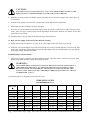
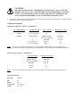
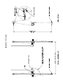
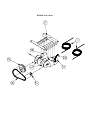
BOATHOUSE
BH9004E
INSTRUCTIONS
REIMANN & GEORGER CORPORATION
MARINE PRODUCTS
P/N 6112172
BUFFALO, NY 14225
06/01/01
SAFETY PRECAUTIONS
Please read and thoroughly understand the following safety precautions and instruction manuals
before using your RGC Boathouse Lift. If you have any questions, contact the dealer who sold you
the lift.
1)
Before allowing anyone to operate the lift, be certain they fully understand the proper operating
procedures.
2)
Be certain to install the lift as specified in instruction manual. Not doing so can cause
equipment damage and or personal injury.
3)
Always wear leather gloves when handling wire rope.
4)
All electrical equipment must be inspected and installed by a certified electrician in accordance
with local electrical codes.
5)
Have your electrician ensure that a Ground Fault Circuit Interrupter (G.F.C.I.) is installed and
working properly.
6)
Tighten all nuts and bolts securely before using the lift.
7)
Keep people and pets away from lift during its operation. Do not allow swimming or playing
around or on the lift.
8)
Do not exceed the maximum weight capacity of the lift that can lead to serious personal injury
and/or equipment failure.
9)
Completely remove all loads from the lift before performing any type of maintenance or
repair on it.
10) Do not work on or in the boat when it is attached to the lift.
11) Periodically inspect the wire rope for wear or damage. Check the wire rope ends to ensure that
they are securely fastened. Immediately replace any worn or damaged wire rope.
12) Inspect the pulleys and bearings to be certain that they spin freely. Lubricate or replace them
immediately.
13) A boat with water in it from a rain storm may exceed the weight capacity of the lift. Be certain to
drain the boat before lifting it all the way up to its resting place. Make sure you replace the plug
before launching your boat.
RGC MARINE PRODUCTS
PHONE: ( 716 ) 895 –1156
INSTALLATION AND SETUP
PRE-INSTALLATION CHECKS
1.
Insure you have received all specified parts as listed in supplied parts list.
2.
Consult licensed professional engineer to inspect and approve boathouse structure for this type of application and
loading capacity.
WARNING:
INSURE BOATHOUSE STRUCTURE HAS BEEN DESIGNED FOR THIS TYPE OF
APPLICATION AND CONSTRUCTED IN ACCORDANCE WITH LOCAL BUILDING AND
ELECTRICAL CODES TO PREVENT PERSONAL INJURY AND / OR EQUIPMENT
DAMAGE.
3.
Do not install or use the lift if it shows any signs of damage.
4.
Do not weld or otherwise modify any part of the lift or power drive. Such alterations may damage the lift and / or
power drive and void the associated warranties.
5.
Two people will be needed to mount the power drive into the boathouse. The following precautions must be observed
when lifting any part of this equipment:
a.
Be sure of your footing.
b.
Bend your knees and lift with your legs.
c.
Hold the equipment section close to your body when lifting.
WARNING:
USE A MINIMUN OF TWO PERSONS TO INSTALL THE POWER DRIVE INTO THE
BOATHOUSE TO PREVENT PERSONAL INJURY AND/OR EQUIPMENT DAMAGE.
LIFT ASSEMBLY
Supporting beams must be installed to the spacing required by the boat to be lifted. The hangers will fit beams 6”
wide by 6” to 9” deep.
1.
Assemble #37X and #38X hangers and clamps to each corner of the boathouse beams about 6” wider than the beam of
the boat.
2.
Using 2 x 6 or 2 x 8 pressure treated wood planks, construct two mounting bases for the power drives. Center them on
the fore and aft beams between the hangers.
3.
Temporarily clamp the power drive to the wood mounting base and position it so that the centerlines of the speed
reducers are askew to the centerlines of the two boathouse beams. Ensure that the power drive is positioned to that the
winch spools are at right angles to the wire rope line pull. Refer to the reeving diagram.
4.
When the power drive is positioned properly, drill two 1/2” holes through the wood mounting base using the power
drive frame as a template. Fasten the frame in place with the supplied 1/2” hardware, reference part # 8, 9 and 10.
5.
Remove pipe plugs on sides of the reducers closest to the ceiling of boathouse and install supplied vent plugs.
CAUTION:
FAILURE TO INSTALL THE VENT PLUG CAN CAUSE PREM ATURE FAILURE OF THE
REDUCER SEALS AFTER EXTENDED USE AND VOID YOUR W ARRANTY.
6.
Mount the reversing switches in a suitable location protected from water and near enough to each other to allow for
easy operation.
7.
Assemble safety latches to ends of hooks. Attach hooks to plain double blocks with shackles.
8.
Attach pulley blocks to all hangers as shown in diagram.
9.
Reeve the wire rope through the blocks and spools as shown. Be careful to wind the rope in tight, even layers on the
spools. If the wire rope is wound properly from the beginning it will not kink or break the wire strands. Secure cable
ends with wire rope clamps.
10. Attach the slings or I-beam cradles to the lifting blocks per their instruction.
11. Refer to Power Supply Connections Section Before Proceeding.
12. Pull the boat into the lift and raise it up slowly. If one corner tightens before the others, lower the boat.
13. Slide some wire rope through the loop in the spool from the loose corner toward the tight one to level the boat. If the
blocks twist on themselves when unhooked, loosen the cable clamps at the block and unwind the wire rope until the
block hangs straight. Retighten the clamps.
POWER SUPPLY CONNECTIONS
1.
Insure power supply is compatible with motor nameplate ratings. The motor must be connected to a properly rated
branch circuit to help minimize voltage drops during operation.
WARNING:
THE POWER DRIVE AND SUPPLY LINE MUST BE INSTALLED AND INSPECTED BY A
CERTIFIED ELECTRICIAN IN ACCORDANCE WITH LOCAL ELECTRICAL CODES.
BECAUSE WATER AND ELECTRICITY ARE POTENTIAL SAFETY HAZARDS, THIS
INSTALLATION MUST INCLUDE A PROPERLY WORKING GROUND FAULT CIRCUIT
INTERRUPTER. (G.F.C.I.)
Use the following wire sizing guide in wiring the power drive.
WIRE SIZING GUIDE
FOR REFERENCE ONLY
Distance Î
Motor amps
Ð
50 feet
100 feet
150 feet
200 feet
250 feet
300 feet
350 feet
400 feet
5 amp
7.5 amp
10 amp
12.5 amp
15 amp
17.5 amp
20 amp
22.5 amp
25 amp
#12 awg
#12 awg
#12 awg
#12 awg
#10 awg
#10 awg
#10 awg
#10 awg
#8 awg
#12 awg
#12 awg
#10 awg
#10 awg
#10 awg
#10 awg
#8 awg
#8 awg
#8 awg
#10 awg
#10 awg
#10 awg
#10 awg
#8 awg
#8 awg
#8 awg
#8 awg
#6 awg
#10 awg
#10 awg
#8 awg
#8 awg
#8 awg
#8 awg
#6 awg
#6 awg
#6 awg
#8 awg
#8 awg
#8 awg
#8 awg
#6 awg
#6 awg
#6 awg
#6 awg
#4 awg
#8 awg
#8 awg
#6 awg
#6 awg
#6 awg
#6 awg
#4 awg
#4 awg
#4 awg
#6 awg
#6 awg
#6 awg
#6 awg
#4 awg
#4 awg
#4 awg
#4 awg
#2 awg
#6 awg
#6 awg
#4 awg
#4 awg
#4 awg
#4 awg
#2 awg
#2 awg
#2 awg
Awg. - American Wire Gauge Amp. - Motor Full Load Current Feet - Distance From MAIN Breaker Box to Ctrl Panel
CAUTION:
THE ABOVE CHART IS ONLY A REFERENCE FOR WIRE SIZING. DO NOT USE THIS
INFORMATION TO ACTUALLY SIZE THE WIRE TO YOUR POWER DRIVE. YOU MUST
CONSULT A LICENSED ELECTRICAL CONTRACTOR WHO WILL DETERMINE THE
ACTUAL WIRE SIZE REQUIRED TO SUIT YOUR PARTICULAR APPLICATION.
2.
Use plastic zip ties and any other supplies needed to tie off the electrical cords. This protects the cords from abrasion,
sharp objects, water contact and other harm.
WIRING PROCEDURES
Salzer Reversing Switch - 110VAC ( 3/4 HP Motors)
INCOMING POWER
BLACK
WHITE
GREEN
Note:
to
SALZER SWITCH
3 (3,7,11 jumpered)
1 (1,5,9 jumpered)
GROUND BAR
2
4
8 (6,8 jumpered)
12 (10,12 jumpered)
to
MOTOR FEED to
na
na
GREEN / BARE
YELLOW or WHITE
ORANGE
BLACK
RED
MOTOR JUNC. BOX
na
na
GROUND
T1 & T3
T2 & T4
T8
T5
To reverse motor direction operation, reverse wiring of Black (T8) & Red (T5) at motor junction box.
For motors greater than 3/4 hp, a higher rated switch must be used. Contact RGC for additional information.
Remote Control - 110 VAC (3/4 HP Motors)
RC MOTOR FEED
GREEN / BARE
YELLOW or WHITE
ORANGE
BLACK
RED
Note:
to
MOTOR JUNC. BOX
GROUND
T1 & T3
T2 & T4
T8
T5
To reverse motor direction operation, reverse wiring of Black (T8) & Red (T5) at motor junction box.
Motor Specifications
RGC PN:
HP:
RPM:
VOLTAGE:
AMPS:
6500684
3/4
1725
115 / 208-230
8.2 / 4.5-4.1
BOATHOUSE – 9000 LB.
PARTS LIST
Each reference number in the following parts lists can be matched with the reference number referred to in both the text and
illustrations.
# 3103042 – BH9004E BOAT LIFT
# 3103040 – BH9004 COP 1 OF 2
REF #
1
2
4
5
6
PART #
3106098
3106099
7303112
7303115
7303116
QTY
4
8
4
4
4
DESCRIPTION
BH #37X HANGER
BH #38X HANGER
BLK HOOK SGL W / LATCH
BLK HOOK DBL W/ LATCH
BLK PLAIN DBL
# 3103041 – BH9004 COP 2 OF 2
REF #
7
8
9
10
PART #
3102204
5806314
3106510
QTY
4
16
1
7306460
5806286
5806400
5806379
5806380
7300151
7300154
7301152
12
4
4
4
12
4
4
4
DESCRIPTION
BH9004 CA 3/16 x 60’ - TINNED
5/8-11 X 10” HHCS
BH9004 BOB
consisting of:
3/16" WIRE ROPE CLAMP
1/2-13 X 2-1/2” HHCS
1/2" WASHER FLAT SAE
1/2-13 NUT HEX
5/8-11 NUT HEX
HOOK G320CN 1-1/2T
LATCH 1-1/2T G320
SHACKLE 7/16 SCREW
# 3103069 - PD BH 2500/4500 PWR ASSY - 2 UNITS SHIPPED
REF #
12
13
14
15
16
17
18
19
20
21
22
PART #
6500684
6703127
3103126
7300602
7300614
3103065
6703111
5403261
5405001
5003189
5406966
QTY
1
1
2
1
1
1
1
1
15 FT.
1
1
DESCRIPTION
MOTOR BALDOR 3/4HP 115/230V
REDUCER 50:1 DBL SHAFT
BH WINCH SPOOL
SHEAVE LARGE
SHEAVE SMALL
BH FRAME
BELT - V
SWITCH REVERSING 15A
CORD 14/5 PVC BLACK
DRUM SWITCH MTG PLATE
GFCI 15A IN LINE W/CORD & PLUG
BH9004 Power Drive