1
HP 4x Speed
CD–ROM Disk Drive
User’s Guide
Workstation Systems Group
Order No. A1658–90669
Edition E0895
Printed in U.S.A.
Hewlett-Packard Co. 1995
First Printing:
August, 1995
UNIX is a registered trademark in the United States and other countries, licensed exclusively through
X/Open Company Limited.
NOTICE
The information contained in this document is subject to change without notice.
HEWLETT–PACKARD MAKES NO WARRANTY OF ANY KIND WITH REGARD TO THIS
MATERIAL INCLUDING BUT NOT LIMITED TO THE IMPLIED WARRANTIES OF
MERCHANTABILITY AND FITNESS FOR A PARTICULAR PURPOSE. Hewlett-Packard shall
not be liable for errors contained herein or for incidental or consequential damages in connection with
the furnishing, performance or use of this material.
Hewlett-Packard assumes no responsibility for the use or reliability of its software on equipment that is
not furnished by Hewlett-Packard.
This document contains proprietary information which is protected by copyright. All rights reserved.
No part of this document may be photocopied, reproduced or translated to another language without the
prior written consent of Hewlett-Packard Company.
RESTRICTED RIGHTS LEGEND. Use, duplication, or disclosure by government is subject to
restrictions as set forth in subdivision (c) (1) (ii) of the Rights in Technical Data and Computer Software
Clause at DFARS 252.227.7013. Hewlett-Packard Co., 3000 Hanover St., Palo Alto, CA 94304.
10 9 8 7 6 5 4 3 2 1
Contents
Preface
7&+'0%' 8++
#('6; #0& ')7.#614; 6#6'/'065 8++
056#..#6+10 16+%' 8+++
'.#6'& #07#.5 8+++
'8+5+10 +5614; +:
41$.'/5 7'56+105 #0& 7))'56+105 +:
1%7/'06#6+10 108'06+105 :
Chapter 1
Preparing for Installation
'0'4#. '5%4+26+10 #,14 '#674'5 1( 6*' 4+8' 4+8' 08+410/'/6#. '37+4'/'065 4+8' *;5+%#. 2'%+(+%#6+105 4'2#4+0) 61 056#.. 6*' 4+8' 11.5 '37+4'& !'4+(;+0) +6 106'065 '6 6*' &&4'55 &&4'55 7/2'45 4'2#4' 6*' ;56'/ +0).'<0&'& < 75 10(+)74#6+10 10564#+065 < 75 '4/+0#6+10 7+&'.+0'5 19'4 (( 6*' "14-56#6+10 #0& #0; '4+2*'4#.5 iii
Contents
Chapter 2
Using your CD–ROM Drive
!/41 1*5& /.'*(41"3*/. ".% &5*$& *,& .'/1-"3*/. '/1 ".% &5*$& *,& .'/1-"3*/. '/1 /.31/,2 ".% &"341&2 /' 3)& 1*5& 2*.( 3)& 1*5& &%*" &2$1*03*/. *2$ 1"7 &2$1*03*/. /"%*.( " *2$ *. " /1*8/.3",,7/4.3&% 1*5& .,/"%*.( " *2$ *. " /1*8/.3",,7/4.3&% 1*5& /"%*.( " *2$ *. " &13*$",,7 /4.3&% 1*5& .,/"%*.( " *2$ *. " &13*$",,7 /4.3&% 1*5& /4.3*.( " *2$ .-/4.3*.( " *2$ &"%*.( 3)& 427 *()3 Chapter 3
Maintenance and Troubleshooting
"1*.( '/1 3)& *2$2 1/4#,&2)//3*.( )&$+ 3)& %%1&22 &33*.(2 '/1 *.(,&.%&% 1*5&2 )&$+ 3)& "1%6"1& .23",,"3*/. &$)&$+ 3)& %%1&22 &33*.(2 &1*'7 3)& 723&- 0&1"3*/. 42*.( 400/13"5& &-/5", .% &0,"$&-&.3 1/$&%41&2 *&,% &0,"$&"#,& .*32 /6&1 '' 3)& 723&- &-/5*.( ".% &0,"$*.( 3)& 1*5& iv
Contents
Appendix A
Safety and Regulatory Statements
*(//(,+/ $&1) 0(,+/ $#$. ) ,**1+(" 0(,+/ ,**(//(,+ + #( + $- .0*$+0 ,% ,**1+(" 0(,+/ *(//(,+/ $&1) 0(,+/ ,*-)( +"$ ",1/0("/ $&1) 0(,+ + ,(/$ $") . 0(,+ ,. "'(+$/ )$"0.,/0 0(" (/"' .&$ .$" 10(,+/ /$. %$02 0 0$*$+0 ,. +)2 ) // /$. !$)/ .+(+&/ +# 10(,+/ Appendix B
SCSI Connector Pinout
v
Contents
Figures
3 -$$# .(2$ 3 -$$# '4/(" ) -$"(%(" 0(,+/ ##.$// $00(+&/ .(2$ ,+0.,)/ +# $ 01.$/ (/" . 4 ) "(+& 0'$ (/" (+ 0'$ (/" . 4 ,.(5,+0 ,1+0 $*,2(+& 0'$ (/" (+ 0'$ (/" . 4 ,.(5,+0 ,1+0 +/$.0(+& (/" $.0(" ) ,1+0 $*,2(+& (/" %.,* 0'$ (/" . 4 $.0(" ) ,1+0 Table
(+&)$+#$# 1/ ,+%(&1. 0(,+ ,+/0. (+0/ -$. !1/ .(2$ -$. 0(+& ,+0.,)/ +# $ 01.$/ ,++$"0,. (+,10/ vi
Preface
The HP 4x Speed CD–ROM Disc Drive User’s Guide describes how to install, configure,
and use the HP 4x Speed CD–ROM Disc Drive with an HP 9000 Series 700 workstation.
We’ve organized this guide as follows:
Chapter 1
Describes the preparation procedures for installing the CD–ROM Disc
Drive into the system.
Chapter 2
Describes the installation procedures for the CD–ROM Disc Drive and
how to verify the CD–ROM Disc Drive installation.
Chapter 3
Describes what to do if you experience problems when attempting to use
the CD–ROM Disc Drive. It also explains how to check the installation of
the new CD–ROM Disc Drive.
Audience
This guide is intended for use by anyone familiar with the HP 9000 Series 700 Owner’s
Guide who wants to install and configure the CD–ROM Drive.
Safety and Regulatory Statements
See Appendix A in the back of this manual for the safety and regulatory statements that
apply to the HP 4x Speed CD–ROM Disc Drive.
vii
Preface
Installation Notice
Products designated in the applicable Hewlett-Packard price list as customer-installable
can be installed by computer-knowledgeable customers who carefully read and follow the
instructions provided. Customers who elect to have the product installed by our field
personnel are charged the applicable field installation charge, as covered under the
standard terms and conditions. For more information, please contact your local sales
representative.
Related Manuals
For more information, refer to the following documents:
viii
•
The Owner’s Guide that came with your system
•
HP-UX Installing Peripherals: HP 9000 Series 700 (B2355–90006)
•
Using Your HP Workstation (A2615–90003)
•
HP Visual User Environment User’s Guide (B1171–90061)
•
System Administration Tasks HP 9000 Series 700 Computers (B2355–90040)
•
Using HP-UX (B2910–90001)
Preface
Revision History
The revision history for each edition of the manual is listed below:
Edition
Revision History
E0895
First Printing.
Problems, Questions, and Suggestions
If you have any questions or problems with our hardware, software, or documentation,
please contact either your HP Response Center or your local HP representative.
ix
Preface
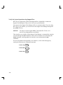
Documentation Conventions
Unless otherwise noted in the text, this guide uses the following symbolic conventions:
literal values
Bold words or characters in formats and command descriptions
represent commands that you must use literally. Pathnames are
also in bold.
user-supplied
values
Italic words or characters in formats and command descriptions
represent values that you must supply. Italics are also used in
text for emphasis.
screen display
Information that the system displays appears in this typeface.
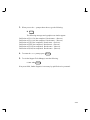
Return
A rectangle with rounded corners and a key label denotes a key on
your keyboard. (In this manual we refer to the Return key. On
your keyboard the key may be labeled either Return or Enter.)
This symbol indicates the end of a chapter or part of this guide.
x
Chapter 1
Preparing for Installation
This document describes the HP 4x Speed CD–ROM drive, and its installation, operation
and maintenance.
This chapter introduces the CD–ROM drive and contains the following information:
•
General description of the CD–ROM drive
•
Major features of the CD–ROM drive
•
Preparing to install the CD–ROM drive
•
Power off the workstation and any peripherals.
1–1
Introduction
General Description
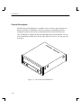
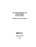
The HP 4x Speed CD–ROM drive is a random access, read–only, mass storage device
that uses removable CD–ROM discs. The drive contains a semiconductor laser for
reading data optically, and includes an embedded controller with a SCSI interface.
The CD–ROM drive supports the ISO 9660 and High Sierra format standards. You can
access information from the drive like any other disk drive, however, you may not write
to the drive.
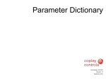
Figure 1–1. HP 4x Speed CD–ROM Drive
1–2
Introduction
Major Features of the CD–ROM Drive
The CD–ROM drive offers the following features:
•
12cm/8cm discs
•
600 kB sustained transfer rate
•
Supports 1X, 2X or 4X rotational modes
•
190 ms random access time
•
150 ms random seek time
•
Built–in SCSI-2 controller
•
Electric Load/Eject tray
•
Emergency Eject
•
Remote SCSI ID jumper block
•
Horizontal or vertical physical orientation
•
Software Volume Control (L/R channel independent)
•
Snap–on bezel
•
Continuous rotary volume control for headphones
1–3
Introduction
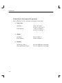
CD–ROM Drive Environmental Requirements
The CD–ROM drive has the following environmental requirements:
•
Temperature
Operating
Non–Operating
•
Altitude
Operating
Non–Operating
•
3000 m (10000 ft.)
12000 m (40,000 ft.)
Humidity
Operating @ 22 deg. C
Non–Operating @ 60 deg. C
1–4
5 deg. C to 50 deg. C
(41 deg. F to 122 deg. F)
–10 deg. C to 60 deg. C
(14 deg. F to 140 deg. F)
8% to 80 %RH (Non–Condensing)
5% to 95 %RH (Non–Condensing)
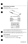
Introduction
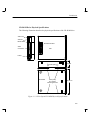
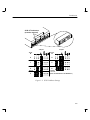
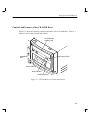
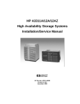
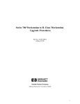
CD–ROM Drive Physical Specifications
The following illustration describes the physical specifications of the CD–ROM drive.
Audio Out
SCSI ID
Mode Select
Terminator Socket
SCSI
Connector
TOP
Power
REAR
LEFT AND RIGHT SIDES
4–M3 (TAP)
4.3 cm
19.6 cm
BOTTOM
4–M3 (TAP)
12 Location
Mounting Screws
14.95 cm
Figure 1–2. HP 4x Speed CD–ROM Physical Specifications
1–5
Introduction
Preparing to Install the CD–ROM Drive
The following information is provided to prepare the CD–ROM for installation.
Tools Required
The following tools are needed to install the CD–ROM drive:
•
#2 Phillips screwdriver
•
Small needle–nose pliers
Verifying Kit Contents
Verify that the kit contains one of each of the following:
•
CD–ROM drive (drive P/N A4325–60001)
•
Set of 4 screws (M4x6)
•
Power adapter cable
•
SCSI I/O cable
•
Static strap
•
HP 4x Speed CD–ROM Disk Drive User’s Guide (A1658–90669)
NOTICE:
If any contents of your kit are missing, contact your sales
representative.
Minimum Requirements
Minimum requirement for the HP–UX operating system is level 9.03 for the HP 4x
Speed CD–ROM drive.
NOTICE:
1–6
You must use software patch PHSS_5764 under HP–UX 9.03, 9.05
and 9.07 to run SupportWave successfully.
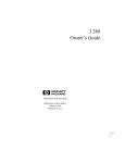
Introduction
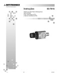
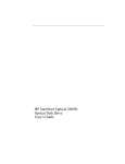
Set the SCSI–2 Address
The CD–ROM drive must have a unique SCSI–2 target address. The CD–ROM drive’s
jumpers are set, at the factory, to the SCSI–2 default address of 2 as shown in Figure 1–3.
You must also ensure that the operating mode jumpers are set for correct drive operation.
We ship the drive with the operating mode jumpers set to operate correctly with your
system. We recommend you keep the default address if possible.
CAUTION: SCSI–2 disk drives are susceptible to mechanical and electrostatic
shock. When handling the disk drives, always wear the static–
grounding wrist strap that came in the CD–ROM drive kit. Always
handle the CD–ROM drive carefully.
Electrostatic charges can damage CD–ROM drives. To prevent
such damage from occurring, observe the following precautions
during unpacking and installation:
•
•
•
•
Stand on a static–free mat.
Wear a static strap to ensure that any accumulated electrostatic charge
discharges from your body to ground.
Connect all equipment together, including the static–free mat, static
strap, routing nodes, and peripheral units.
Keep uninstalled CD–ROM drives in their protective antistatic bags.
Use the following instructions to set the SCSI–2 address jumpers on your drive:
1–7
Introduction
Address Jumpers
To set the drive’s address, use the SCSI–2 address jumpers. Perform the following steps
to set the drive’s address:
1.
Attach the static–grounding wrist strap by following the instructions on the package
that contains the strap. Attach one end of the strap to the system chassis.
2.
Locate the address jumpers on the rear of the CD–ROM drive, as shown in
Figure 1–3.
3.
Set the drive’s SCSI–2 target address to an address that’s not used by another
SCSI–2 device. Use jumpers, as shown in Figure 1–3; use needlenose pliers to set
the jumpers.
NOTICE:
Do not use SCSI–2 address 7 because the system’s SCSI–2
controller uses address 7 by default. We advise that you do not use
SCSI–2 address 6 because the root disk drive uses it.
Ensure that the SCSI–2 terminators are removed.
1–8
Introduction
SCSI–2 Terminators
(must be removed)
Jumpers
Jumpers
Target
ID
Target
ID
0
4
1
5
2
Default
3
6
Default
for /root
(NOT recommended for CD–ROM drive)
Figure 1–3. SCSI–2 Address Settings
1–9
Introduction
Prepare the System
Perform the following steps to prepare the system for the CD–ROM drive installation:
1.
Determine the existing SCSI–2 address settings currently in use on your system.
Before installing the drive, determine which SCSI–2 ID address settings are already
being used on your system by completing the following substeps:
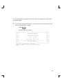
2.
If you are using HP–UX 9.05, enter the following at the prompt:
/etc/ioscan –d scsi
RETURN
After a few moments the ioscan utility lists all of the SCSI I/O devices it could find.
If there is a SCSI CD–ROM drive in the list, that listing appears similar to the following:
H/W Path
Description
Status
====================================
2.0.1.2.0 scsi
ok(nnnnnnnn)
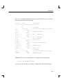
If you are using HP–UX 10.0, enter the following at the prompt:
/usr/sbin/ioscan –d sdisk
1–10
RETURN
Introduction
After a few moments the ioscan utility lists all of the SCSI I/O devices it could find.
The list appears similar to the following:
H/W Path
Class
Description
============================================
bc
8
bc
I/O Adapter
8/0
ext_bus
GSC built–in Fast/Wide SCSI Interface
8/0.0
target
8/0.0.0
disk
QUANTUM LPS1080WD
8/0.5
target
8/0.5.0
disk
DEC
DSP3210SW
8/0.6
target
8/0.6.0
disk
DEC
DSP3210SW
8/12
ba
Core I/O Adapter
8/12/5
ext_bus
Built–in SCSI
8/12/5.2
target
8/12/5.2.0
disk.
TOSHIBA CD–ROM XM–4101TA
8/12/5.4
target
8/12/5.4.0
disk.
SEAGATE ST3600N
8/12/5.6
target
8/12/5.6.0
disk
MICROP 2112
10
bc
I/O Adapter
10/12
ext_bus
GSC add–on Fast/Wide SCSI Interface
10/12.4
target
10/12.4.0
disk
SEAGATE ST31200W
If ioscan does not see your CD–ROM drive it returns the following message:
ioscan: No hardware found
If you receive this message, go to Chapter 3, “Maintenance and Troubleshooting.”
1–11
Introduction
3.
Shut down the system.
If you are running HP–UX under HP VUE, shut down your system by performing
the shutdown procedure described in your Owner’s Guide which came with your
workstation.
If you are running HP–UX without HP VUE, shut down your system by typing the
following command:
# /etc/shutdown –h
RETURN
You must have superuser privileges to use the /etc/shutdown command. If you do
not have superuser privileges, contact your system administrator.
If your workstation is part of a cluster, refer to the Managing Clusters of HP 9000
Computers manual for instructions on shutting down.
1–12
Introduction
Single-Ended SCSI-2 Bus Configuration Constraints
For the single-ended SCSI-2 bus, HP-UX supports only one of each type of removablemedia disk drive (i.e., floppy disk, CD-ROM, or magneto-optical drives) and two of the
same type tape devices (i.e., 4-mm DDS tape drives or 9-track tape drives), per SCSI bus.
You may connect no more than seven SCSI-2 devices to each single-ended SCSI-2 bus.
Table 1–1 shows the configuration constraints for each single-ended SCSI-2 device type.
You may connect no more than seven SCSI-2 device IDs to each single-ended SCSI-2
bus. Some SCSI-2 devices use more than one SCSI-2 drive address. Each address must
be accounted for in the maximum number of SCSI-2 devices allowed.
CAUTION: Do not connect single-ended SCSI-2 devices to a differential
SCSI-2 bus or differential SCSI-2 devices to a single-ended SCSI-2
bus. Connecting a SCSI-2 device to the wrong SCSI-2 bus can
cause system failure.
1–13
Introduction
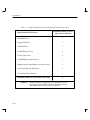
Table 1–1. Single-Ended SCSI-2 Bus Configuration Constraints (per bus)
Single-Ended SCSI-2 Devices
Hard Disk Drives
7
Floppy Disk Drives
1
CD-ROM Drives
1
4-mm DDS Tape Drives
2
9-Track Tape Drives
2
650-MB Magneto-Optical Drives
1
Magneto-Optical Autochangers (see notice below)
1
8-mm Cartridge Tape Subsystem
2
8 Serial Port Terminal Server
1
Maximum Number of SCSI-2 Devices (per bus)
7
NOTICE:
1–14
Maximum Number of Each
Type of Device Allowed
Magneto-Optical Autochangers use more than one SCSI-2
drive address. Each address must be accounted for in the
maximum number of SCSI-2 devices allowed.
Introduction
SCSI-2 Bus Termination Guidelines
There are certain guidelines to follow when terminating a SCSI-2 bus. These guidelines
are:
CAUTION: Unless the SCSI-2 bus is properly terminated, the bus will not
operate. Terminators provide impedance matching on SCSI-2 bus
signal lines.
•
•
The last device connected to the SCSI-2 bus must be terminated with a SCSI-2
terminator. Use a Hewlett-Packard K2291 50-pin low-density bail-lock active
terminator or a Hewlett-Packard C2904A high-density thumbscrew active
terminator to terminate the last SCSI-2 option device.
Any termination on other devices on the bus must be removed. This includes
external termination plugged into a SCSI-2 receptacle on the device, or internal
resistor packs. (Refer to peripheral device or system configuration manuals for
termination information).
1–15
Introduction
Power Off the Workstation and any Peripherals
To power off the workstation and any peripherals, perform the following steps:
1.
Power off the workstation, using the power switch on the front of the workstation.
CAUTION: Do not power off your workstation without first shutting down
HP–UX. Powering off with HP–UX still running could damage the
data on the disks associated with your workstation.
If you are already at the boot–administration level (the level used to check the SCSI–2
IDs), you do not need to shut down before powering off.
If you accidentally rebooted HP–UX while determining the address settings, see “Prepare
the System,” earlier in this chapter, for instructions on shutting down HP–UX.
2.
Disconnect the power cord from the rear of the workstation and the wall outlet.
3.
Power off any external peripherals attached to your workstation, and unplug their
power cables from the wall outlet.
You are now ready to begin the hardware installation of your new CD–ROM drive. The
step–by–step instructions for installing the drive are found in your Owners Guide.
1–16
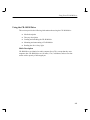
Chapter 2
Using Your CD–ROM Drive
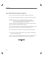
This chapter provides the following information on using your CD–ROM drive:
•
Your CD–ROM drive configuration
•
Controls and features of the CD–ROM drive
•
Using the CD–ROM drive
NOTICES: The CD–ROM drive is a read–only device. You may access files
stored on a CD–ROM disc, but you cannot write to a CD–ROM
disc.
All instructions in this chapter assume your CD–ROM drive SCSI
ID is set to 2 – the default ID set by the factory.
All SCSI devices can use the scsi device driver.
To verify HP–UX system operation, see your System’s Owners Guide
For more information on checking or reconfiguring the kernel for a device driver or file,
see the System Administration Tasks Manual: HP 9000 Series 700 Computers.
2–1
Using Your CD–ROM Drive
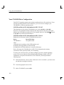
Your CD–ROM Drive Configuration
Your HP–UX operating system comes with preconfigured device files and drivers. If you
use these preconfigured device files and drivers, you won’t need to configure your
CD–ROM drive with the operating system.
SCSI ID and Device File Information for HP–UX 9.05
The defauilt device files for the CD–ROM drive are in the /dev/dsk or /dev/rdsk
directories. The underlined number located in the sixth position in the device file name
indicates the SCSI address used in the file. For example, the device file c201d2s0 located
in /dev/dsk was created for SCSI address 2.
SCSI ID and Device File Information for HP–UX 10.0
Default device file names for the CD–ROM is shown below.
Device
CD–ROM drive
Device File Name
/dev/[r]dsk/c#t#d#
where
c# identifies the bus address of the SCSI interface card
t# identifies the target address of the SCSI disk
d# identifies the SCSI lun address (0, except for disk arrays)
Device file names for CD_ROM drives at HP–UX 10.0 depend on the naming
conventions of the system on which you are installing.
To create your own device files, you must reconfigure your drive with the operating
system. You can use either the System Administration Manager (SAM) or HP–UX
commands to set up the kernel and device files. With each, you must perform the
following steps:
2–2
1.
Check the kernel for a device driver. If the device driver is not there, you must create
one and then reconfigure the kernel.
2.
Create the appropriate device files.
3.
Add a CD–ROM file system (cdfs).
Using Your CD–ROM Drive
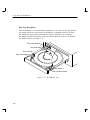
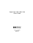
Controls and Features of the CD–ROM Drive
Figure 2–1 shows the operating controls and features of the CD–ROM drive. Table 2–1
describes each of these controls and features.
CD–ROM Disc
Loading Tray
Emergency Eject
Headphone
Jack
Volume Control
Busy Indicator
Load/Eject Button
Figure 2–1. CD–ROM Drive Controls and Features
2–3
Using Your CD–ROM Drive
Table 2–1. CD–ROM Drive Operating Controls and Features
Control/Feature
Purpose
Eject Button
Press the Eject Button to eject the disc tray. When the drive is in
use, you must unmount the disc before ejecting it. Refer to the
subsection “Unmounting a CD–ROM disc” for instructions on
umounting a disc.
Busy Indicator
The Busy Indicator lights during a data access operation and
blinks during a data transfer. The indicator stays out when there is
one of the following:
•
Defective disc
•
Disc insertion error (for example, an upside–down disc)
•
No disc present
Disc Loading Tray
Tray for loading the disc. Eject the disc tray to insert or remove a
disc. The tray does not open if the drive power is off.
Emergency Eject
By inserting the end of a paper clip, you can eject the disc tray if
the workstation does not have power.
2–4
Using Your CD–ROM Drive
Using the CD–ROM Drive
This section provides the following information about using the CD–ROM drive:
•
•
•
•
•
Media description
Disc tray description
Loading and unloading the CD–ROM disc
Mounting and unmounting a CD–ROM disc
Reading the drive’s busy light
Media Description
CD–ROM discs are identical to audio compact discs (CDs), except that they store
computer data. CD–ROM discs are 120 mm (4.7 in.) in diameter, and use one data
surface with a capacity of 600 megabytes.
2–5
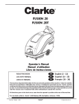
Using Your CD–ROM Drive
Disc Tray Description
This CD–ROM drive is mounted either horizontally or vertically. The disc tray has three
disc holders which are used when the CD ROM drive is mounted vertically. The three
disc holders are spring loaded to hold the disc in place. When the drive is mounted
horizontally, the three disc holders are not used and are held out of the way by the three
disc holder retainers. (see Figure 2–2)
Disc Holder Retainer
DIsc Holder A
DIsc Holder B
Disc Holder Retainer
Disc Holder C
Disc Holder Retainer
Figure 2–2. CD–ROM Disc Tray
2–6
Using Your CD–ROM Drive
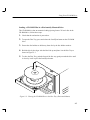
Loading a CD–ROM Disc in a Horizontally Mounted Drive
This CD–ROM drive has an automatic loading/ejecting feature. To load a disc in the
CD–ROM drive, follow these steps:
1.
Check that the workstation is powered on.
2.
To open the Disc Tray, press and release the Load/Eject button on the CD–ROM
drive.
3.
Ensure the disc holders are held away from disc by the disc holder retainers.
4.
Hold the disc by the edges with the label side up and place it in the Disc Tray as
shown in Figure 2–3.
5.
To close the Disc Tray, push the front of the disc tray gently towards the drive until
it closes by itself or press the Load/Eject button.
Figure 2–3. Placing the CD–ROM Disc in the Disc Tray (Horizontal Mount)
2–7
Using Your CD–ROM Drive
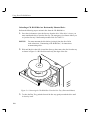
Unloading a CD–ROM Disc in a Horizontally Mounted Drive
Perform the following steps to unload a disc from the CD–ROM drive:
1.
Press the eject button to eject the disc tray from the drive. If the drive is in use, you
must unmount the disc to eject the disc tray. The emergency eject feature allows you
to eject the disc tray if the normal procedure fails. See Table 2–1.
NOTICE:
2.
You must unmount the disc before ejecting it from the drive. Refer
to the subsection, “Unmounting a CD–ROM Disc,” for instructions
on unmounting a disc.
Wait until the drive has fully ejected the disc tray, then remove the disc from the tray
as shown in Figure 2–4. Be careful to touch only the edges of the disc.
Figure 2–4. Removing the CD–ROM Disc From the Disc Tray (Horizontal Mount)
3.
2–8
To close the Disc Tray, push the front of the disc tray gently towards the drive until
it closes by itself.
Using Your CD–ROM Drive
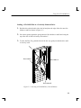
Loading a CD–ROM Disc in a Vertically Mounted Drive
1.
Hold the disc with the label side to the left and place the edge of the disc onto disc
holders A and B as shown in Figure 2–5.
2.
Press down gently against the spring tension of disc holders A and B and swing the
top of the disc in until it is held by disc holder C.
3.
To close the Disc Tray, push the front of the disc tray gently towards the drive until
it closes by itself.
Disc Holder A
Disc Holder C
Disc Holder B
Figure 2–5. Inserting a CD–ROM Disc (Vertical Mount)
2–9
Using Your CD–ROM Drive
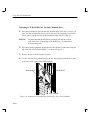
Unloading a CD–ROM Disc in a Vertically Mounted Drive
1.
Press the eject button to eject the disc tray from the drive. If the drive is in use, you
must you must unmount the disc to eject the disc tray. The emergency eject feature
allows you to eject the disc tray if the normal procedure fails. See Table 2–1.
NOTICE:
You must unmount the disc before ejecting it from the drive. Refer
to the subsection, “Unmounting a CD–ROM Disc,” for instructions
on unmounting a disc.
2.
Press down gently against the spring tension of disc holders A and B and swing the
top of the disc away from disc holder C, as shown in Figure 2–6
3.
Remove the disc from disc holders A and B.
4.
To close the Disc Tray, push the front of the disc tray gently towards the drive until
it closes by itself or press the Load/Eject button.
Disc Holder A
Disc Holder C
Disc Holder B
Figure 2–6. Removing a CD–ROM Disc from the Disc Tray (Vertical Mount)
2–10
Using Your CD–ROM Drive
Mounting a CD–ROM Disc
To access your CD–ROM drive, you must mount a CD–ROM disc every time you insert
it into the drive.
CAUTION: Failure to mount a disc may cause a system error condition and
may also require rebooting the system.
Perform the following steps to mount a disc:
1.
Insert the CD–ROM disc into the disc tray, as described in “Inserting and Removing
CD–ROM Discs Into and From the Disc Tray,” earlier in this chapter.
2.
Load the disc tray into the drive, as described in “Loading a CD–ROM Disc Tray,”
earlier in this chapter.
3.
Using the mkdir command, create a mount directory (for example, /cdrom) to
define where to access the CD–ROM file system, as shown:
mkdir /cdrom
4.
Return
Mount the CD–ROM disc every time you insert it into the drive. The mount
command uses the following syntax:
mount sfname directory –options
where
sfname is the name of the block device file associated with the drive
containing the file system to be mounted.
directory is the mount point directory in the existing file system where
the file system is to be mounted.
options are any restrictions specified by the user.
2–11
Using Your CD–ROM Drive
Mount all CD–ROM discs using the mount command with –t cdfs options. The
following example uses the preconfigured block device file /dev/dsk/c201d2s0 for
the CD–ROM drive, set for default SCSI address 2, and /cdrom as the mount directory. The device
Using HP–UX 9.05
/etc/mount /dev/dsk/c201d2s0 /cdrom –t cdfs
Using HP–UX 10.0
/etc/mount /dev/dsk/c#t#d# /cdrom –t cdfs
Return
Return
c# identifies the bus address of the SCSI interface card
t# identifies the target address of the SCSI disk
d# identifies the SCSI lun address (0, except for disk arrays)
Device file names for CD_ROM drives at HP–UX 10.0 depend on the naming conventions of the system on which you are installing.
5.
Now you can access the CD–ROM disc as you would any other mounted file
system. Enter the following command to change your working directory to the
CD–ROM disc:
cd /cdrom
Return
Unmounting a CD–ROM Disc
You must unmount the CD–ROM disc before you eject it from the drive.
CAUTION: You must unmount the CD–ROM disc every time you unload it
from the drive. Failure to unmount a disc can cause a system error
condition and may also require rebooting the system.
NOTICE:
2–12
Before you unmount a CD–ROM disc, make sure that your working directory is set to a directory other than the one under which
the disc was mounted.
Using Your CD–ROM Drive
Use the following procedure to unmount a CD–ROM disc:
1.
Unmount the disc by entering the following:
Using HP–UX 9.05
/etc/umount /dev/dsk/c201d2s0
Using HP–UX 10.0
/etc/umount /dev/dsk/c#t#d#
Return
Return
2.
Press the eject button on the CD–ROM drive.
3.
Remove the disc from the drive.
2–13
Using Your CD–ROM Drive
Reading the Busy Light
The CD–ROM busy light shows the status of the drive during self test and during activity
with the host system.
The CD–ROM drive performs a self test when one of the following happens:
•
You insert a disc into the drive.
•
You turn on the drive with a disc already loaded.
For the self test, the busy light operates in the following sequence:
1.
Light On – The busy light goes on when the disc loads into the drive.
2.
Light Flashing – The light flashes 12 times while a read test is performed on the
disc.
3.
Light Off – The light goes off when the self test is complete.
The busy light goes off when one of the following conditions exist:
•
Defective disc
•
Disc insertion error (for example, an upside–down disc)
•
No disc present
•
A CD–ROM drive power failure exists.
•
The drive is idle on the SCSI bus.
The busy light flashes at 3.2 second intervals when cleaning is required for either the disc
or optics.
The busy light flashes at 1.6 second intervals when playing an audio track.
The busy light stays on during normal activity with the system.
2–14
Chapter 3
Maintenance and Troubleshooting
This chapter provides the following information on maintenance and troubleshooting
your CD–ROM drive:
•
Caring for CD–ROM discs
•
Troubleshooting
•
Removal and Replacement Procedures
3–1
Caring for the CD–ROM Discs
Use the following guidelines to help care for your CD–ROM discs.
•
•
•
3–2
Use CD–ROM discs in a clean environment to prevent dust particles from
scratching disc surfaces.
Store CD–ROM discs in a cool, dry place to prevent moisture and heat damage.
If the CD–ROM disc is dirty, wipe it with a soft cloth. Don’t try to clean the
surface of a CD–ROM disc with cleaning solvents, as some cleaning solvents
may damage the disc.
Troubleshooting
If you have trouble with any of these procedures for using your CD–ROM drive, see
your System Owners Guide
This chapter explains what to do if you experience problems during the configuration
process. It also explains how to run the Support Tool Manager or the Extended Self Test
to verify your system.
If you are experiencing difficulty booting the system, reconfiguring HP–UX, or using the
CD–ROM drive, complete each of the following tasks, in the order they are presented,
until you discover and correct the problem:
•
Check the address settings of any single–ended SCSI–2 devices.
•
Check that you have installed the hardware correctly.
•
Recheck the device list.
•
Run verification tests.
Check the Address Settings for Single–Ended Drives
Check the address settings of each single–ended SCSI–2 device on the bus. Make sure
that no device has the same address setting of another. If you find two devices with the
same address, change one of the devices to a different, unused address setting. To check
the address settings for each single–ended SCSI–2 device, type the following in a
terminal window or HP–UX command line:
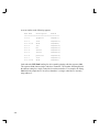
If you are using HP–UX 9.0x, enter the following at the prompt:
/etc/ioscan
RETURN
3–3
A screen similar to the following appears:
H/W Path
Description
Status
====================================
1.0.0
graphics
ok(0x577)
2.0.1
scsi
ok(0x7071)
2.0.1.2.0
disk
ok(0x202)
2.0.2
lan
ok(0x7072)
2.0.3
hil
ok(0x7073)
2.0.4
serial
ok(0x7075)
2.0.5
serial
ok(0x7075)
2.0.6
parallel
ok(0x7074)
2.0.7
scsi
ok(0x707c)
2.0.7.6.0
disk
ok(0x101)
Look under the H/W Path heading for device paths beginning with the sequence 2.0.1.
The sequence 2.0.1 denotes single–ended scsi controller. The number following 2.0.1 is
the address setting for a single–ended device on that controller. For example, the listing
2.0.1.2.0 in the sample device list tells us that there is a single–ended device currently
using address 2.
3–4
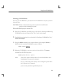
If you are using HP–UX 10.0, enter the following at the prompt:
/usr/sbin/ioscan –d sdisk
RETURN
After a few moments the ioscan utility lists all of the SCSI I/O devices it could find.
The list appears similar to the following:
H/W Path
Class
Description
============================================
bc
8
bc
I/O Adapter
8/0
ext_bus
GSC built–in Fast/Wide SCSI Interface
8/0.0
target
8/0.0.0
disk
QUANTUM LPS1080WD
8/0.5
target
8/0.5.0
disk
DEC
DSP3210SW
8/0.6
target
8/0.6.0
disk
DEC
DSP3210SW
8/12
ba
Core I/O Adapter
8/12/5
ext_bus
Built–in SCSI
8/12/5.2
target
8/12/5.2.0
disk.
TOSHIBA CD–ROM XM–4101TA
8/12/5.4
target
8/12/5.4.0
disk.
SEAGATE ST3600N
8/12/5.6
target
8/12/5.6.0
disk
MICROP 2112
10
bc
I/O Adapter
10/12
ext_bus
GSC add–on Fast/Wide SCSI Interface
10/12.4
target
10/12.4.0
disk
SEAGATE ST31200W
3–5
Check the Hardware Installation
Perform the following steps to check the hardware installation:
CAUTION: The CD–ROM drive is susceptible to mechanical and electrostatic
shock. When handling the drive, always wear the static strap that
came in the CD–ROM drive kit. Always handle the drive carefully.
1.
Check that the SCSI–2 terminator is connected to the single–ended SCSI–2 port on
the rear I/O panel of the system unit (if there are no external SCSI–2 devices), or
that the last external single–ended SCSI–2 device is terminated.
2.
Attach the static–grounding wrist strap by following the instructions on the package
that contains the strap.
3.
Shut down HP–UX.
NOTICE:
If you are already at the boot administration level, you do not need
to shut down; skip this step and go on to Step 4.
If you are running HP–UX under HP VUE, shut down your system by performing
the shutdown procedure described in your Owner’s Guide which came with your
workstation.
If you are running HP–UX without HP VUE, shut down your system by typing the
following command:
# /etc/shutdown –h
RETURN
You must have superuser privileges to use the /etc/shutdown command. If you do
not have superuser privileges, contact your system administrator.
If your workstation is part of a cluster, refer to the Managing Clusters of HP 9000
Computers manual for instructions on shutting down.
4.
3–6
Power off the workstation, using the power switch on the front of the workstation.
CAUTION: Do not power off your workstation without first shutting down
HP–UX. Powering off with HP–UX still running could damage
the data on the disks associated with your workstation.
5.
Remove the drive and check the jumpers, as described in Removal and Replacement
Procedures at the end of this chapter.
6.
Replace the drive.
7.
Check the cable connections of your CD–ROM drive. Make sure that the connectors
are aligned and seated correctly.
8.
Recheck the device list (see the next section).
Recheck the Address Settings
Check the address settings again to see if the drive is now listed (see the “Check the
Address Settings” section, earlier in this chapter).
If the CD–ROM drive and all other SCSI–2 devices available to you before you installed
the CD–ROM drive are now listed, run the system verification test for your software
version, as explained in the next sections.
If the CD–ROM drive is still not listed, or one of the SCSI–2 devices available to you
before you installed the CD–ROM drive is still not listed, contact your service
representative.
3–7
Verify the System Operation using SupportWave
HP–UX uses a diagnostics product called SupportWave. SupportWave contains the
Support Tools Manager so that you can verify your system operation.
You can access the Support Tools Manager while in a terminal window. If you are using
HP–VUE as your interface, you can also access the Support Tools Manager through the
sys_admin directory.
NOTICE:
You must use software patch PHSS_5764 under HP–UX 9.03, 9.05
and 9.07 to run SupportWave successfully.
Three interfaces are available with the Support Tools Manager: a command line interface
(accessed through the cstm command), a menu–driven interface (accessed through the
mstm command), and the graphical user interface (accessed through the xstm
command).
For more information on SupportWave user interfaces, see the online man pages by
entering the following at a command line prompt:
# man cstm
# man mstm
# man xstm
3–8
RETURN
RETURN
RETURN
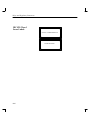
To run SupportWave from either HP VUE or the HP–UX command line shell, perform
the following steps:
1.
To invoke the command line interface, in a terminal window or command line shell,
type the following at the # prompt:
# cstm
RETURN
The following screen appears:
********************************************************************
******
******
******
SUPPORT TOOLS MANAGER
******
******
******
******
Command Line Interface
******
******
******
******
Version A.00.12
******
******
******
******
Part Number B2478–10002
******
******
******
******
(C) Copyright Hewlett Packard Co. 1991, 1992
******
******
All Rights Reserved
******
******
******
********************************************************************
Please wait. System mapping in progress . . .
Please type HELP or ? to list available commands.
CSTM>
3–9
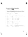
2.
To verify the system operation, type the following at the CSTM> prompt:
CSTM> verify all
RETURN
Messages that are similar to the following appear:
Verification has started on device (CPU).
Verification has started on device (FPU).
Verification has started on device (0/0/0).
Verification has started on device (2/0/1.5.0).
Verification has started on device (2/0/1.6.0).
Verification has started on device (2/0/2).
CSTM>Message from (0/0/0):
This graphics test displays a number of graphics images on the screen of
the graphics device being tested. If an X server is not currently running on that display,
X Windows will be started and run for the duration of the test. The Starbase shared
library (/usr/lib/libsb.sl) should be present to run this test.
CAUTION: This test will fail if any portion of the test window is modified
or overlaid in any way.
NOTE: If a VUE login screen is currently displayed on the monitor, the test
will wait until someone logs in the HP VUE on the graphics monitor to release the lock.
The test stops if the Screen Saver times out, it runs again once the Screen is activated.
WARNING: Do not run this exerciser with any other operation.
(Type ’R’ for Ready, Type ’S’ for Skip) [R] >>
3–10
3.
When you see the >> prompt shown above, type the following:
R
RETURN
The following messages and a graphics test window appear:
Verification of (2/0/1.5.0) has completed. Result status – (Success).
Verification of (2/0/1.6.0) has completed. Result status – (Success).
Verification of (CPU) has completed. Result status – (Success).
Verification of (FPU) has completed. Result status – (Success).
Verification of (2/0/2) has completed. Result status – (Success).
Verification of (0/0/0) has completed. Result status – (Success).
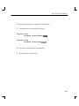
4.
To return the CSTM> prompt, press
5.
To exit the Support Tools Manager, enter the following:
CSTM> exit
RETURN
.
RETURN
If any tests failed, further diagnosis is necessary by qualified service personnel.
3–11
Removal and Replacement Procedures
The Removal and Replacement Procedures for the CD–ROM Drive follow.
CAUTION: Electrostatic charges can damage the integrated circuits on printed
circuit boards. To prevent such damage from occurring, follow
proper ESD precautions
Field Replaceable Units
The following components are authorized for field replacement.
Description
Part Number
CD–ROM Drive
A4325–60001
Before performing the Removal and Replacement Procedures, observe the following
precautions:
1.
Please refer to your system’s Owner’s Guide for the procedures to power off the
system.
2.
Unplug the system unit power cord and the power cords of any peripheral devices
from the power source.
3.
Unplug the system unit power cord from the back of the system unit.
WARNING: Failure to properly shut down and remove power from the system
may create a personal hazard, or may result in hardware damage or
data corruption.
Removing and Replacing the CD–ROM Drive
To open your system, remove and reinstall the CD–ROM drive, refer to your system
Owners Guide. Pre–installation information is found in Chapter 1 of this document.
3–12
Appendix A
Safety and Regulatory Statements
This appendix contains the following safety and regulatory statements:
•
Emissions regulations
•
Emissions regulations compliance
•
Acoustics
•
Electrostatic discharge precautions
•
Laser Safety Statement
•
Warnings and cautions
A–1
Safety and Regulatory Statements
Emissions Regulations
Federal Communications Commission (FCC)
The Federal Communications Commission of the U.S. government regulates the radio
frequency energy emanated by computing devices through published regulations. These
regulations specify the limits of radio frequency emission to protect radio and television
reception. All HP Apollo nodes and peripherals have been tested and comply with these
limits. The FCC regulations also require that computing devices used in the U.S. display
the agency’s label and that the related documentation include the following statement:
NOTICE:
This equipment has been tested and found to comply with the limits
for a Class A digital device, pursuant to part 15 of the FCC rules.
These limits are designed to provide reasonable protection against
harmful interference when the equipment is operated in a commercial environment. This equipment generates, uses, and can radiate
radio frequency energy and, if not installed and used in accordance
with the instruction manual, may cause harmful interference to radio communications. Operation of this equipment in a residential
area is likely to cause harmful interference in which case the user
will be required to correct the interference at his own expense.
Canadian Department of Communications (CDC)
This digital apparatus does not exceed the Class A limits for radio noise emissions from
digital apparatus as set out in the Radio Interference Requirements of the Canadian Department of Communications.
A–2
Safety and Regulatory Statements
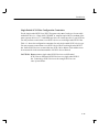
Emissions Regulations Compliance
Any third-party I/O device installed in HP Apollo system(s) must be in accordance with
the requirements set forth in the preceding Emissions Regulations statements. In the
event that a third-party noncompliant I/O device is installed, the customer assumes all
responsibility and liability arising therefrom.
Acoustics
Regulation On Noise Declaration For Machines –3. GSGV
Lpa <70dB
operator position
normal operation
per ISO 7779
Lpa <70dB
am Arbeitsplatz
normaler Betrieb
nach DIN 45635 T.19
A–3
Safety and Regulatory Statements
Electrostatic Discharge (ESD) Precautions
Electrostatic charges can damage the integrated circuits on printed circuit boards. To prevent such damage from occurring, observe the following precautions during board unpacking and installation:
•
•
•
•
•
A–4
Stand on a static-free mat.
Wear a static strap to ensure that any accumulated electrostatic charge is discharged from your body to ground.
Connect all equipment together, including the static-free mat, static strap, routing
nodes, and peripheral units.
Keep uninstalled printed circuit boards in their protective antistatic bags.
Handle printed circuit boards by their edges, once you have removed them from
their protective antistatic bags.
Safety and Regulatory Statements
LASERTURVALLISUUS LOUKAN 1 LASERLAITE KLASS 1 LASER
APPARAT
HP 4x Speed CD–ROM–lukulaite sisältää laitteensisäisen CD–ROM–yksikön, joka on
laserlaite.
Kyseinen CD–ROM–yksikkö on käyttäjän kannalta turvallinen luokan 1 laserlaite. Normaalissa käytössä yksikön suojakotelo estää lasersäteen pääsyn laitteen ulkopuolelle.
CD–ROM–yksikön on tyyppihyväksynyt Suomessa laserturvallisuuden osalta Työministeriön työsuojeluosasto. Laitteen turvallisuusluokka on määritetty valtioneuvoston
päätöksen N:o 472/1985 ja standardin SFS–EN 60825 (1992) mukaisesti.
Tiedot CD–ROM–yksikössä käytettävän laserdiodin säteilyominaisuuksista:
Aallonpituus
Teho
1,1 µW
Luokan 1 laser
790 nm
Laser Safety Statement (For U.S.A. Only)
The CD ROM mass–storage system is certified as a Class–1 laser product under the U.S.
Department of Health and Human services (DHHS) Radiation Performance Standard according to the Radiation Control for Health and Safety Act of 1968.
This means that the mass–storage system does not produce hazardous laser radiation. Because laser light emitted inside the mass–storage system is completely confined within
protective housings and external covers, the laser beam cannot escape from the machine
during any phase of user operation.
A–5
Safety and Regulatory Statements
IEC 825 Class 1
Laser Labels
CLASS 1 LASER PRODUCT
LASER KLASSE 1
A–6
Safety and Regulatory Statements
Warnings and Cautions
WARNING:
Removing device cover may expose sharp edges in equipment chassis. To avoid injury,
use care when installing customer add-on devices.
WARNUNG:
Das Entfernen der Geräteabdeckung legt die scharfen Kanten im Inneren des Gerätes
frei. Um Verietzungen zu vermeiden, seien Sie vorsichtig beim Einbau von
zusätzlichen Bauteilen, die vom Kunden selber eingebaut werden können.
AVERTISSEMENT:
Des bords tranchants du châssis de l’équipement peuvent être exposés quand le cache
de l’unité n’est pas en place. Pour éviter des blessures, faire très attention lors de
l’installation de modules supplémentaires par le client.
WARNING:
Disconnect power plug from wall outlet or source power before moving or removing the
device, or installing add-on components.
WARNUNG:
Entfernen Sie die Stromzuführung von der Steckdose oder der Stromquelle bevor Sie
das Gerät bewegen, abbauen, oder zusätzliche Bauteile installieren.
AVERTISSEMENT:
Débrancher la fiche de la prise de courant ou de la source d’alimentation électrique
avant de déplacer ou de retirer l’unité, ou avant d’installer des modules supplémentaires.
CAUTION:
System power cord must be plugged into an accessible dedicated ac mains receptacle.
VORSICHT:
Das System-Netzanschlußkabel muß an eine zugängliche spezielle Wechselstrom–
Hauptzuführungssteckdose angeschlossen werden.
ATTENTION:
Le fil d’alimentation électrique du système doit être branché dans une prise de courant
c.a. spécialisée accessible.
A–7
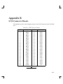
Appendix B
SCSI Connector Pinouts
This appendix provides a table listing the pinouts for the SCSI Connector on the CD–ROM
drive.
Table B–1. SCSI Connector Pinouts
PIN
1
2
3
4
5
6
7
8
9
10
11
12
13
14
15
16
17
18
19
20
21
22
23
24
25
SIGNAL
GND
DB(0)
GND
DB(1)
GND
DB(2)
GND
DB(3)
GND
DB(4)
GND
DB(5)
GND
DB(6)
GND
DB(7)
GND
DB(P)
GND
GND
GND
GND
GND
GND
OPEN
PIN
26
27
28
29
30
31
32
33
34
35
36
37
38
39
40
41
42
43
44
45
46
47
48
49
50
SIGNAL
TERMPWR
GND
GND
GND
GND
GND
–ATN
GND
GND
GND
–BSY
GND
–ACK
GND
–RST
GND
–MSG
GND
–SEL
GND
–C/D
GND
–REQ
GND
–I/O
B–1
Order Number: A1658–90669
Edition E0895
Printed in U.S.A.