1
HP Network Adapter
Software and Configuration Guide
Part Number 441877-00B
March 2007 (Second Edition)
© Copyright 2005-2007 Hewlett-Packard Development Company, L.P.
The information contained herein is subject to change without notice. The only warranties for HP products and services are set forth in the express
warranty statements accompanying such products and services. Nothing herein should be construed as constituting an additional warranty. HP
shall not be liable for technical or editorial errors or omissions contained herein.
Confidential computer software. Valid license from HP required for possession, use or copying. Consistent with FAR 12.211 and 12.212,
Commercial Computer Software, Computer Software Documentation, and Technical Data for Commercial Items are licensed to the U.S.
Government under vendor’s standard commercial license.
Microsoft, Windows, and Windows NT are U.S. registered trademarks of Microsoft Corporation.
Windows Server 2003 is a trademark of Microsoft Corporation. Intel, Pentium, and Itanium are
trademarks or registered trademarks of Intel Corporation or its subsidiaries in the United States and other
countries. UNIX is a registered trademark of The Open Group.
Audience assumptions
This document is for the person who installs, administers, and troubleshoots servers and storage systems.
HP assumes you are qualified in the servicing of computer equipment and trained in recognizing hazards
in products with hazardous energy levels.
Contents
Overview..................................................................................................................................... 5
Supported adapters and operating systems................................................................................................... 5
Adapter driver and software information ...................................................................................................... 7
PCI Hot Plug ............................................................................................................................................. 9
Duplex support........................................................................................................................................ 10
Installation ................................................................................................................................. 13
Download latest drivers, firmware, and documentation ................................................................................ 13
Windows Server 2003 and Windows Server 2003 x64 .............................................................................. 13
Windows 2000 and Windows NT ............................................................................................................ 15
Linux...................................................................................................................................................... 20
SCO OpenServer and UnixWare .............................................................................................................. 21
Solaris ................................................................................................................................................... 23
NetWare ............................................................................................................................................... 28
Firmware upgrade utility .............................................................................................................. 48
Windows utility ....................................................................................................................................... 48
c-Class BladeSystem utility ........................................................................................................................ 54
Linux utility ............................................................................................................................................. 54
DOS utility.............................................................................................................................................. 59
Adapter configurations ................................................................................................................ 62
HP NC-Series Broadcom adapters ............................................................................................................. 62
Keywords for Q57 NDIS2 driver ..................................................................................................... 62
Keywords for B06 NDIS2 driver ...................................................................................................... 63
PXE configuration: HP NC-series Broadcom and Multifunction adapters ................................................ 64
HP NC-Series Multifunction adapters.......................................................................................................... 66
Accelerated iSCSI devices .............................................................................................................. 66
iSCSI boot configuration: Multifunction adapters ............................................................................... 67
PXE configuration: HP NC-series Broadcom and Multifunction adapters ................................................ 67
HP NC-Series Intel adapters...................................................................................................................... 69
Boot Agent ................................................................................................................................... 69
Keywords for N100 NDIS2 driver ................................................................................................... 81
Keywords for N1000 NDIS2 driver ................................................................................................. 87
PXE configuration for HP NC-Series Intel adapters.............................................................................. 89
Windows ............................................................................................................................................... 91
Modifying adapter properties using the NCU.................................................................................... 91
Modifying HP NC-Series Broadcom and Multifunction adapter properties ............................................. 98
Modifying HP NC-Series Intel adapter properties ............................................................................. 103
Modifying NC31xx Fast Ethernet adapter properties........................................................................ 106
Modifying adapter properties in Windows NT ................................................................................ 107
Novell Netware .................................................................................................................................... 110
Advanced Server Program for NetWare ......................................................................................... 110
NetWare Client 32 driver installation for HP adapters...................................................................... 120
Solaris ................................................................................................................................................. 122
Team properties........................................................................................................................ 126
Adapter teaming ................................................................................................................................... 126
Contents
3
Multifunction gigabit server adapter teaming ............................................................................................ 129
Windows 2000 and Windows NT4 teaming............................................................................................ 130
NetWare teaming ................................................................................................................................. 139
VLAN properties ....................................................................................................................... 150
VLAN information.................................................................................................................................. 150
ProLiant Essentials ..................................................................................................................... 151
Networking pack installation .................................................................................................................. 151
Intelligent Networking Pack-Windows Edition............................................................................................ 151
Intelligent Networking Pack-Linux Edition .................................................................................................. 152
Accelerated iSCSI for stand-alone and c-Class BladeSystem Multifunction server adapters .............................. 153
Accelerated iSCSI for embedded HP Multifunction server adapters .............................................................. 153
Diagnostics .............................................................................................................................. 154
PCI shared interrupts.............................................................................................................................. 154
HP NC-Series Intel adapter diagnostics .................................................................................................... 154
HP NC-Series Broadcom adapter diagnostics............................................................................................ 156
HP NC-Series Broadcom Multifunction adapter diagnostics......................................................................... 167
Technical support...................................................................................................................... 172
Before you contact HP............................................................................................................................ 172
HP contact information ........................................................................................................................... 172
Free automated customer support services ................................................................................................ 172
Acronyms and abbreviations...................................................................................................... 174
Index....................................................................................................................................... 176
Contents
4
Overview
In this section
Supported adapters and operating systems ................................................................................................. 5
Adapter driver and software information..................................................................................................... 7
PCI Hot Plug ............................................................................................................................................ 9
Duplex support....................................................................................................................................... 10
Supported adapters and operating systems
Supported adapters
The Network Configuration Utility (NCU) supports the following HP Fast Ethernet and Gigabit Server
Adapters.
Standup adapters:
•
HP NC110T PCI Express Gigabit Server Adapter
•
HP NC150T PCI 4-port Gigabit Combo Switch Adapter
•
HP NC310F PCI-X Gigabit Server Adapter
•
HP NC320T PCI Express Gigabit Server Adapter
•
HP NC340T PCI-X Quad Port Gigabit Server Adapter
•
HP NC360T PCI Express Dual Port Gigabit Server Adapter
•
HP NC364T PCI Express Quad Port Gigabit Server Adapter
•
HP NC370T PCI-X Multifunction Gigabit Server Adapter
•
HP NC370F PCI-X Multifunction Gigabit Server Adapter
•
HP NC373F PCI Express Multifunction Gigabit Server Adapter
•
HP NC373T PCI Express Multifunction Gigabit Server Adapter
•
HP NC380T PCI Express Dual Port Multifunction Gigabit Server Adapter
•
HP NC1020 Cu Gigabit Server Adapter 32 PCI Single Port
•
HP NC3123 Fast Ethernet Server Adapter *
•
HP NC3132 Fast Ethernet Upgrade Module (Dual 10/100) for the NC3134 Server Adapter *
•
HP NC3133 100FX Upgrade Module for the NC3134 Server Adapter *
•
HP NC3134 Fast Ethernet Server Adapter (Dual Base 10/100) *
•
HP NC3135 Fast Ethernet Upgrade Module (Dual 10/100) for the NC3134 Server Adapter *
•
HP NC6132 1000 SX Gigabit Upgrade Module for the NC3134 Server Adapter*
•
HP NC6133 1000 LX Gigabit Upgrade Module for the NC3134 Server Adapter *
•
HP NC6134 Gigabit Server Adapter (PCI 1000 SX)
Overview 5
•
HP NC6136 Gigabit Server Adapter (PCI 1000 SX)
•
HP NC6170 Dual Port PCI-X Gigabit Server Adapter
•
HP NC6770 PCI-X Gigabit Server Adapter
•
HP NC7131 Gigabit Ethernet Server Adapter
•
HP NC7132 Gigabit Ethernet Upgrade Module for the NC3134 Server Adapter *
•
HP NC7170 Dual Port PCI-X Gigabit Server Adapter
•
HP NC7770 PCI-X Gigabit Server Adapter
•
HP NC7771 PCI-X Gigabit Server Adapter
Embedded adapters:
•
HP NC320i PCI Express Gigabit Server Adapter
•
HP NC324i PCI Express Dual Port Gigabit Server Adapter
•
HP NC325i PCI Express Dual Port Gigabit Server Adapter
•
HP NC326i PCI Express Dual Port Gigabit Server Adapter
•
HP NC370i PCI-X Multifunction Gigabit Server Adapter
•
HP NC371i PCI-X Multifunction Gigabit Server Adapter
•
HP Embedded NC373i Multifunction Gigabit Server Adapter
•
HP NC3161 Fast Ethernet Server Adapter *
•
HP NC3163 Fast Ethernet Server Adapter *
•
HP NC7760 PCI-X Gigabit Server Adapter
•
HP NC7761 PCI-X Gigabit Server Adapter
•
HP NC7780 Gigabit Server Adapter
•
HP NC7781 PCI-X Gigabit Server Adapter
•
HP NC7782 Dual Port PCI-X Gigabit Server Adapter
Mezzanine adapters:
•
HP NC320m PCIe Gigabit Server Adapter
•
HP NC325m PCI Express Quad Port 1Gb Server Adapter for c-Class BladeSystem
•
HP NC326m PCI Express Dual Port 1Gb Server Adapter for c-Class BladeSystem
•
HP NC373m PCI Express Dual Port Multifunction Gigabit Server Adapter for c-Class BladeSystem
•
HP NC374m PCI Express Dual Port Multifunction Gigabit Server Adapter
* Not supported in Windows Server 2003 x64
Supported operating systems
These server adapters are supported on the following operating systems.
Microsoft
•
Windows Server 2003 x64 Editions
•
Windows Server 2003
Overview 6
•
Windows® 2000 (NDIS5)
•
Windows NT® 4.0 (NDIS4) (only supported on adapters that shipped before January 1, 2003)
•
DOS NDIS2*
NetWare
•
NetWare 6.5 Server
•
NetWare 6.6 Server
•
NetWare Open Enterprise Server
Linux 32
•
Red Hat Enterprise Linux 5
•
Red Hat Enterprise Linux 4
•
Red Hat Enterprise Linux 3
•
SUSE Linux Enterprise Server 10 Service
•
SUSE Linux Enterprise Server 9 Service
Linux 64
•
Red Hat Enterprise Linux 5 for AMD64 and Intel EM64T
•
Red Hat Enterprise Linux 4 for AMD64 and Intel EM64T
•
Red Hat Enterprise Linux 3 for AMD64 and Intel EM64T
•
SUSE Linux Enterprise Server 10 for AMD64 and Intel EM64T
•
SUSE Linux Enterprise Server 9 for AMD64 and Intel EM64T
UNIX
•
Unixware 7.x
•
OpenUnix 8.x
•
Open Server 5.x/6.x
Solaris
•
Solaris 10
•
Solaris 9
* Unattended Install Only. Also, DOS NDIS2 is not supported for NC3133 adapters.
Adapter driver and software information
To obtain driver and software information for Microsoft® Windows Server 2003 x64, Microsoft®
Windows Server 2003, Microsoft® Windows® 2000, Microsoft® Windows NT® (4.0), Novell
NetWare, SCO OpenServer, UnixWare, Linux, and Solaris:
1.
Go to the HP website (http://www.hp.com).
2.
Click Software & Driver Downloads from the left menu bar.
3.
Type the product name in the For product box and press Enter. For example, type NC370T.
4.
Select an operating system.
Overview 7
5.
Click HP ProLiant Networking Software.
6.
Click download and save the HP SoftPaq (sp#####.exe) file to a directory on your hard drive. The
SoftPaq file is a self-extracting executable with a file name based on the SoftPaq number.
7.
Click the SoftPaq file to extract the files and then open the cmponent.htm file.
Drivers
Drivers are found in the following folders:
•
Microsoft® Windows Server 2003 \WIN2003
•
Microsoft® Windows Server 2003 x64 \WIN2003x64
•
Microsoft® Windows® 2000 \WIN2000
•
Microsoft® Windows NT® 4.0 \NT4
•
Novell NetWare \NETWARE\SERVER
•
Linux \LINUX
•
UnixWare 7.x and OpenServer 6.x \UNIX\UNIXWARE7_OPENSERVER6
•
Solaris 9 and Solaris 10 \SOLARIS
•
Unattended Install \DOS
Supplemental applications in \APPS
•
Boot agent
•
Diagnostic tests including MFDIAG.exe, N100X.exe and Q57.exe
•
Online firmware upgrade utility
•
Multifunction firmware upgrade utility
•
c-Class BladeSystem firmware upgrade utility
•
Linux firmware upgrade utility
Device-specific information
See \docs\files.txt for a descriptive list of all files in the SoftPaq.
Release notes and other documentation in \docs
•
HP Accelerated iSCSI for Multifunction Network Adapters (AiSCSIUG.pdf)
•
HP Network Adapter License Utility for Windows (NALICNSE.pdf)
•
HP Network Adapter Scripting Utility (NICSCRPT.pdf)
•
HP Network Configuration Agent (ncuasr.pdf)
•
HP ProLiant Essentials Intelligent Networking Pack–Linux Edition (PEINPL.pdf)
•
HP ProLiant Essentials Intelligent networking Pack–Windows Edition (PEINPW.pdf)
•
HP Virus Throttle for Windows License Utility (VTLICNSE.pdf)
•
HP NC510x PCIe 10 Gb Software Configuration Guide (NC510x PCIe 10 Gb Software Guide.pdf)
•
Network adapter user guides (\docs\hw)
•
Release notes (Relnotes.txt)
•
SetLACState Utility (SetLAC.pdf)
Overview 8
Linux documentation
•
Linux readme.txt file is located in the \LINUX directory
•
HP iSCSI Boot User Guide for Linux in the \docs directory
PCI Hot Plug
PCI Hot Plug is an industry-standard solution that provides increased system availability and non-stop
serviceability in business-critical computing environments. PCI Hot Plug enables PCI networking adapters
to be replaced or added to a server without taking the system down. HP pioneered this technology and
has worked closely with the PCI Special Interest Group (SIG) and several key industry partners to
accelerate its adoption as an industry standard. PCI Hot Plug technology also has a broad range of
industry support from leading operating system suppliers including Microsoft® and Novell.
HP server adapters support PCI Hot Plug technology. To take advantage of this solution, you must use the
adapter in an HP or third-party system that supports PCI Hot Plug. To implement PCI Hot Plug, use the
configuration instructions that come with your system. If you use an HP system that supports PCI Hot Plug,
refer to the documentation for configuring and installing PCI Hot Plug devices in the HP SmartStart
application, which ships with HP systems.
If you use a third-party system that supports PCI Hot Plug, refer to the documentation that came with your
system or contact technical support for the vendor.
Support for enabling PCI Hot Plug
Different operating systems support PCI Hot Plug in different ways. The following list describes how
different operating systems enable PCI Hot Plug devices.
•
•
•
•
Windows® 2000, Windows Server 2003, and Windows Server 2003 x64
o
Can replace like item for like item
o
Can add a new adapter to an empty slot
o
Can add an option module to an existing NC3134 adapter
Windows NT® 4.0
o
Can replace like item for like item
o
Cannot add a new adapter to an empty slot
NetWare 6.x
o
Can replace like item for like item
o
Can remove an adapter
o
Can add a new adapter to an empty slot
o
Can add an option module to an existing NC3134 adapter (This feature is not supported on an
NC3134 adapter that has a persistent driver installed.)
UnixWare 7.x and OpenServer 6.x
Requires hardware that implements PCI Hot Plug failover and a DDI 8 MDI driver that implements the
CFG_SUSPEND and CFG_RESUME subfunctions to the entry point routine. This lets the system
administrator suspend the driver, power down the slot, hot-swap or hot-replace the adapter, power
up the slot, and resume the driver, all without bringing the machine down. For further information
about PCI Hot Plug support, refer to your UNIX documentation.
•
SCO OpenServer 5.x
Overview 9
No support
•
Linux
No support
Upgrading the adapter with a persistent driver
To upgrade the adapter with a persistent driver:
1.
Manually remove (unload) the driver.
2.
Power down the slot and remove the adapter.
3.
Upgrade the adapter (add the option module).
4.
Reinstall the upgraded adapter.
5.
Power up the slot to let NetWare automatically detect the (upgraded) adapter.
Duplex support
Duplexing is a performance option that allows you to choose how the adapter sends and receives packets
over the network. Duplex options include:
•
Auto. (Auto-negotiation) The adapter negotiates with the full-duplex switch to send and receive
packets at the highest rate. The switch must support auto-negotiation. If the switch does not support
auto-negotiation, the adapter defaults to half-duplex.
NOTE: An exception is the HP NC3133 adapter, which defaults to full-duplex.
•
Full-duplex. (Requires full-duplex switch) The adapter sends and receives packets simultaneously by
using a different wire to perform each function. This feature can improve adapter performance by
eliminating collisions. Set duplex mode to full-duplex ONLY if you have a hub/switch that supports
full-duplex.
•
Half-duplex. The adapter performs one operation at a time (because send and receive lines are
shared); it either sends or receives.
Configuring for full-duplex
If you have an auto-negotiating switch, the adapter automatically matches the duplex setting at the switch.
If you do not have an auto-negotiating switch, you must manually configure the adapter for full-duplex
support.
Configuration is specific to the driver you are loading for your network operating system (NOS). To set up
the duplex mode, refer to the section below that corresponds to your operating system. Note that
performance may suffer if your switch is not full-duplex and you configure the adapter to full-duplex. Leave
the adapter on half-duplex if you are not sure what type of switch to which you are connected.
Windows NT® 4.0
To set the duplex options:
1.
Double-click the HP Network icon in the Control Panel. Or, right-click on Network Neighborhood
and select Properties. Then select the Adapters tab. Double-click on an adapter or team to launch the
CPQNTAC utility.
2.
Select an adapter from the list and click Properties.
Overview 10
3.
Set Speed/Duplex on the adapter to Auto/Auto, 10/Half, 10/Full, 100/Half, 100/Full, or
1000/Full.
4.
Click OK until prompted to restart.
5.
Restart Windows NT® 4.0.
Windows® 2000, Windows Server 2003, and Windows Server 2003 x64
For new installations, Windows® 2000 automatically installs the adapter drivers. Exception: For the
NC150T, NC310F, NC32xx, NC37xx, NC340x, NC1020, NC6136, NC6170, NC71xx and
NC77xx adapters, you must install the appropriate driver components located in the \WIN2000
directory in the HP SoftPaq. Complete the following steps to download the SoftPaq file.
1.
Go to the HP website (http://www.hp.com).
2.
Click Software & Driver Downloads from the left menu bar.
3.
Type the product name in the For product box and press Enter. For example, type NC370T.
4.
Select an operating system.
5.
Click HP ProLiant Networking Software.
6.
Click download and save the HP SoftPaq (sp#####.exe) file to a directory on your hard drive. The
SoftPaq file is a self-extracting executable with a file name based on the SoftPaq number.
7.
Click the SoftPaq file to extract the files and then open the cmponent.htm file.
NOTE: If you need to update existing Windows® 2000 drivers, refer to the instructions in
Windows 2000 installation notes ("Windows 2000 and Windows NT" on page 15).
To set the duplex options:
1.
Launch the Network Configuration Utility.
2.
Select an adapter from the list in the NCU Main window and click Properties. The Adapter
Properties window appears.
3.
On the Settings tab, set the Speed/Duplex Setting for the adapter to Auto/Auto, 10/Half, 10/Full,
100/Half, 100/Full, or 1000/Full.
4.
Click OK twice to accept the configuration changes.
NetWare Server
To set the duplex options, use the following syntax for FORCEDUPLEX and SPEED.
NOTE: The NC340T, NC1020, NC71xx, and NC77xx adapters support full-duplex and halfduplex. The fiber Gigabit adapters support full-duplex mode only and cannot be changed.
•
Syntax: FORCEDUPLEX=n
Where n =
0–auto-negotiation (You must have an auto-negotiating switch/hub (an Nway* switch) to get fullduplex support with the FORCEDUPLEX parameter set to 0 (auto-negotiation).
1–half-duplex
2–full-duplex
NOTE: To set the adapter to half- or full-duplex, you must set the SPEED parameter to either 10
or 100.
Default = auto-negotiate
Overview 11
Examples:
•
o
100 Mbps full-duplex: FORCEDUPLEX=2 SPEED=100
o
10 Mbps full-duplex: FORCEDUPLEX=2 SPEED=10
Syntax: SPEED= n (n = 10 or 100 or 1000)
Specifies the speed the driver uses. If you do not use this parameter, the driver automatically detects
the network speed. If unable to detect the network speed, the driver defaults to 10 Mbps. If you use
this parameter, the driver operates at the specified speed instead of auto-detecting network speed.
NOTE: The NC3133 adapter supports 100 Mbps only. It does not default to 10 Mbps. You
must set the SPEED parameter to either 10 or 100 if you want to set the FORCEDUPLEX
parameter to either half or full. The SPEED parameter is for N100.LAN driver and
N1000.LAN. You cannot change the speed for the Gigabit (fiber) adapters. You can,
however, change the speed for the NC7131 and NC7132 Gigabit (copper) adapters to 10
Mbps or 100 Mbps.
Default = The adapter automatically senses speed.
Other NDIS 2.x-based clients
To set the duplex options in other NDIS 2.x-based clients, edit the PROTOCOL.INI file. Add the
FORCEDUPLEX and SPEED parameters to the N100 section, or the SPEEDUPLEX parameter to the N1000
section. For information on these parameters, refer to Keywords for N100 NDIS2 driver (on page 81) ,
Keywords for N1000 NDIS2 driver (on page 87), or Keywords for Q57 NDIS2 driver (on page 62).
Overview 12
Installation
In this section
Download latest drivers, firmware, and documentation............................................................................... 13
Windows Server 2003 and Windows Server 2003 x64 ............................................................................ 13
Windows 2000 and Windows NT........................................................................................................... 15
Linux..................................................................................................................................................... 20
SCO OpenServer and UnixWare............................................................................................................. 21
Solaris .................................................................................................................................................. 23
NetWare .............................................................................................................................................. 28
Download latest drivers, firmware, and
documentation
HP updates networking software frequently to include new functionality and features. For the latest driver,
firmware, and documentation updates go to the HP website
(http://h18004.www1.hp.com/products/servers/networking/index.html).
Windows Server 2003 and Windows Server 2003
x64
The following provides information about Windows Server 2003 and Windows Server 2003 x64 support
for HP NC-series network adapters.
Windows Server 2003
The following Windows Server 2003 network adapter drivers are used in this release:
•
N100325.sys for NC31xx Fast Ethernet server adapters
•
N1000325.sys for NC310xx, NC340x, NC61xx, and NC71xx server adapters
•
Q57XP32.sys for NC150x, NC32xx, NC10xx, NC67xx, and NC77xx server adapters
•
N1E5132.sys for NC110T, NC360x, NC364x server adapters
•
BXND51X.sys for all Multifunction server adapters
•
NXP2NIC.sys for NC510x 10 Gb server adapters
Components for these drivers are located in the \WIN2003 directory in the HP SoftPaq. Complete the
following steps to download the SoftPaq file.
1.
Go to the HP website (http://www.hp.com).
2.
Click Software & Driver Downloads from the left menu bar.
3.
Type the product name in the For product box and press Enter. For example, type NC370T.
4.
Select an operating system.
Installation 13
5.
Click HP ProLiant Networking Software.
6.
Click download and save the HP SoftPaq (sp#####.exe) file to a directory on your hard drive. The
SoftPaq file is a self-extracting executable with a file name based on the SoftPaq number.
7.
Click the SoftPaq file to extract the files and then open the cmponent.htm file.
Windows Server 2003 x64
IMPORTANT: NC31xx, NC6132, NC6133, and NC7132 adapters are not supported in
Windows Server 2003 x64.
The following Windows Server 2003 x64 network adapter drivers are used in this release:
•
N1G5132E.sys for NC310F, NC340T, NC61xx, and NC71xx server adapters
•
Q57AMD64.sys for NC150T, NC32x, NC1020, NC67xx, and NC77xx server adapters
•
BXVBDA.sys for Multifunction server adapters
•
N1E5132E.sys for NC110T, NC360T, NC364x server adapters
•
NXP2NIC.sys for NC510x 10 Gb server adapters
Components for these drivers are located in the \WIN2003x64 directory in the HP SoftPaq. Complete
the following steps to download the SoftPaq file.
1.
Go to the HP website (http://www.hp.com).
2.
Click Software & Driver Downloads from the left menu bar.
3.
Type the product name in the For product box and press Enter. For example, type NC370T.
4.
Select an operating system.
5.
Click HP ProLiant Networking Software.
6.
Click download and save the HP SoftPaq (sp#####.exe) file to a directory on your hard drive. The
SoftPaq file is a self-extracting executable with a file name based on the SoftPaq number.
7.
Click the SoftPaq file to extract the files and then open the cmponent.htm file.
Installing network drivers (new installations)
When you install the adapter in the server for the first time:
1.
Connect the cable from the adapter to your network.
2.
Provide power to your server.
3.
Start Windows Server 2003 or Windows Server 2003 x64 .
o
For the NC150T, NC310F, NC32xx, NC340x, NC37xx, NC380x, NC1020, NC6136,
NC6170, NC6770, NC71xx, and NC77xx server adapters, you must install the appropriate
driver component located in the \WIN2003 or \WIN2003x64 directory in the HP SoftPaq file.
o
For all other adapters, Windows® automatically detects and installs a driver for the adapter from
its own library of drivers.
Updating network drivers
To update the network driver, follow these instructions:
Locate the driver on the CD, diskette, or directory on your hard drive where you copied it from an
updated source. See Technical Support for a list of online sources for software and driver updates.
Installation 14
1.
Run the appropriate Driver Component Package (listed as CPxxxxxx.exe) in a directory on your hard
drive. The component is a self-extracting executable with a file name based on the component
number.
2.
Click the Install button to proceed with the installation.
3.
After the drivers have been installed, you may delete the Component Package that you copied.
Removing the driver software
To remove the driver software:
1.
Before physically removing an adapter from your system, first remove the adapter driver software.
2.
Start Windows Server 2003 or Windows Server 2003 x64 and log in. You must have Network
Administrator privileges to remove the driver software.
3.
Open the Control Panel and double-click the System icon. In the System Properties dialog box,
select the Hardware tab.
4.
Click Device Manager. The Device Manager window appears.
5.
Click the plus (+) sign to expand the Network adapters. All network adapters appear.
6.
Right-click the adapter to be removed and choose Uninstall.
NOTE: Not all driver files are removed as part of this procedure. The driver and adapter can
be removed via Hot Plug, if supported.
Windows 2000 and Windows NT
The following provides information about Windows 2000 support for HP NC-series network adapters.
The following Windows 2000 network adapter drivers are used in this release:
•
N100NT5.sys for NC31xx Fast Ethernet server adapters
•
N1000NT5.sys for NC310x, NC340x, NC61xx, and NC71xx Gigabit Ethernet server adapters
•
Q57W2K.sys for NC150x, NC32xx, NC10xx, NC67xx, and NC77xx Gigabit Ethernet server
adapters
•
BXVBDX.sys for Multifunction Gigabit server adapters
•
N1E5032.sys for NC360x and NC364T Gigabit Ethernet server adapters
Components for these drivers are located in the \WIN2000 directory in the HP SoftPaq file.
Installing network drivers (new installations)
When you install the adapter in the server for the first time:
1.
Connect the cable from the adapter to your network.
2.
Provide power to your server.
3.
Start Windows Server 2003 or Windows Server 2003 x64 .
o
For the NC150T, NC310F, NC32xx, NC340x, NC37xx, NC380x, NC1020, NC6136,
NC6170, NC6770, NC71xx, and NC77xx server adapters, you must install the appropriate
driver component located in the \WIN2003 or \WIN2003x64 directory in the HP SoftPaq file.
o
For all other adapters, Windows® automatically detects and installs a driver for the adapter from
its own library of drivers.
Updating network drivers from disk
Installation 15
To update the network driver, follow these instructions:
Locate the driver on the CD, diskette, or directory on your hard drive where you copied it from an
updated source. See Technical Support for a list of online sources for software and driver updates.
1.
Run the appropriate Driver Component Package (listed as CPxxxxxx.exe) in a directory on your hard
drive. The component is a self-extracting executable with a file name based on the component
number.
2.
Click the Install button to proceed with the installation.
3.
After the drivers have been installed, you may delete the Component Package that you copied.
Windows NT4 unattended install (push)
The following provides information about Windows NT support for HP NC-series network adapters.
Overview
The primary objective of the Push Installation is to get the client properly connected to the Windows NT®
server before the installation begins using the NDIS2 driver, and to keep the same client connected using
the NDIS4 driver after the Windows NT® server is installed without any end-user action.
The difficulty is that the list of supported adapters on the Windows NT® 4.0 CD-ROM is restricted and
special steps must be performed to update the installation source files and modify the scripts to automate
the process for the adapters not on the list.
Main steps of the process
1.
Create a Network Installation Startup disk from the Windows NT® server and modify it for your
adapter.
2.
Create a shared directory for the Windows NT® server installation files on the Windows NT®
server.
3.
Modify the UNATTEND.TXT installation script to automate the procedure and add the proper
adapter installation and configuration information.
The sample UNATTEND.TXT file, provided in Item 4 of the "Samples and Templates" section,
indicates how to override default registry parameters for the adapter in the [CPQNic1ParamSection]
section. The override parameters should not be used unless the default parameters will not work
properly for a specific installation. The sample parameters are commented out.
4.
Integrate the adapter driver files into the Windows NT® installation source files.
5.
Perform the Unattended Installation bootup with the prepared startup disk from the client system.
Performing an unattended installation on Windows NT 4.0
1.
Prepare a Windows NT® 4.0 server:
a. Create a folder on the server hard disk for the installation files (for example, NT40.INS). Make
this folder shared (for example, with shared name NT40.INS).
b. Create a user (for example, USERID with a password password) and grant read and view rights
for the NT40.INS folder.
2.
Use a CD-ROM drive at the Windows NT® server and copy the i386 folder with Windows NT® 4.0
installation files to the shared folder NT40.INS on this server (for example, using NT Explorer).
3.
Create or modify the installation answer file UNATTEND.TXT as required by your specific system and
desired Windows NT® configurations. UNATTEND.TXT may be read-only and may need to be
made write-able before editing (for example, attrib -r unattend.txt). Refer to the sample
UNATTEND.TXT file with comments.
4.
Create the \CPQANC directory: NT40.INS\i386\DRVLIB.NIC\CPQANC.
Installation 16
5.
Copy driver installation files: Xcopy the HP Configuration and Drivers Disk to the proper location
under Adapter Device Driver folder (NT40.INS\i386\DRVLIB.NIC\CPQANC folder on the
Windows NT® server). This enables the installation program to find the same file structure as on the
Drivers disk. Be sure to use the /s /e switches on xcopy.
6.
On the Windows NT® server, prepare the Microsoft® Client Installation disk using the Windows
NT® Network Client Administrator:
a. Prepare a system diskette (for example, DOS 6.22: format a: /s). Do not use the Windows NT®
system disk.
b. Copy UNATTEND.TXT from \NT40.INS\i386 to the diskette as specified in item 3 above
(preferably to the root (a:\)). The best location to put this file is in the root of your install disk, but
the only requirement is to specify the full path to this file in the AUTOEXEC.BAT for the WINNT
command.
c.
Use the Windows NT® Administrative Tools (Common), start Network Client Administrator and
select Make Network Installation Startup Disk.
d. Set "Existing Path" to use the previously installed software for MS Client or, if it is the first time,
create the shared directory on the server's hard drive, using the Windows NT® 4.0 Server CDROM as a source (for example, by copying from \client on the CD-ROM to c:\client).
e. Choose Network Client v3.0 for MS-DOS and Windows.
f.
Choose any of the Network Adapters from the list (for example, NE2000 compatible).
g. Set Computer name, User name, Domain and Network protocol when prompted.
h. Select OK and wait while files are copied to the disk.
i.
Copy the proper ndis2 dos driver (N100.DOS, N1000.DOS, or Q57.DOS) to this disk in the
\NET directory. N100.DOS, N1000.DOS, Q57.DOS can be found in \DOS\NDIS2\ in the HP
SoftPaq file.
j.
Modify A:\NET\SYSTEM.INI : netcard=N100.DOS (or N1000.DOS or Q57.DOS).
k. Modify A:\NET\PROTOCOL.INI : drivername=N100$ (or N1000$ or Q57$).
l.
Add a line: CACHEFLUSH=1 just after the "drivername = N100$" line.
m. Verify or modify A:\AUTOEXEC.BAT to have the following commands:
NET USE W: \\ServerName\NT40.INS
W:\WINNT /s:W:\ /u:a:\unattend.txt
Note that W is an example for the logical drive mapped to the share on the Windows NT®
server.
n. Remove the invocation of setup.exe from A:\AUTOEXEC.BAT.
7.
Insert the startup disk and boot up your DOS client. After connecting to the network. do one of the
following:
o
Input USERID as a User name when prompted. Input password as a password when prompted.
o
Modify the NET START line in the AUTOEXEC.BAT to NET LOGON USERID PASSWORD /YES.
Samples and templates
•
PROTOCOL.INI
[network.setup]
version=0x3110
netcard=ms$ne2clone,1,MS$NE2CLONE,1
;transport=ms$ndishlp,MS$NDISHLP
Installation 17
;transport=ms$netbeui,MS$NETBEUI
;lana0=ms$ne2clone,1,ms$netbeui
;lana1=ms$ne2clone,1,ms$ndishlp
transport=tcpip,TCPIP
lana0=ms$ne2clone,1,tcpip
[ms$ne2clone]
drivername=N100$
CACHEFLUSH=1
; CACHEFLUSH line is required ONLY IF NDIS2 does not shut down
; properly
;INTERRUPT=3
;IOBASE=0x300
;SlotNumber=1
[protman]
drivername=PROTMAN$
PRIORITY=MS$NDISHLP
;[MS$NDISHLP]
;drivername=ndishlp$
;BINDINGS=ms$ne2clone
;[ms$netbeui]
;drivername=netbeui$
;SESSIONS=10
;NCBS=12
;BINDINGS=ms$ne2clone
;LANABASE=0
[tcpip]
NBSessions=6
DefaultGateway0=
SubNetMask0=255 255 0 0
IPAddress0=137 65 10 12
DisableDHCP=1
DriverName=TCPIP$
BINDINGS=ms$ne2clone
LANABASE=0
•
SYSTEM.INI
[network]
filesharing=no
printsharing=no
autologon=yes
computername=COMPUTERNAME
lanroot=A:\NET
username=Administrator
workgroup=DOMAIN
reconnect=no
directhost=no
dospophotkey=N
lmlogon=0
logondomain=DOMAIN
preferredredir=full
autostart=full
maxconnections=8
Installation 18
[network drivers]
netcard=N100.DOS
;transport=ndishlp.sys,*netbeui
transport=tcpdrv.dos,nemm.dos
devdir=A:\NET
LoadRMDrivers=yes
[Password Lists]
*Shares=a:\net\Share000.PWL
USERID=A:\NET\USERID.PWL
•
AUTOEXEC.BAT
path=a:\net
a:\net\net start
rem a:\net\net logon userid password /yes
net use W: \\ServerName\nt40.ins
W:winnt /s:W:\ /u:a:\unattend.txt
•
UNATTEND.TXT
[Unattended]
OemPreinstall = yes
NoWaitAfterTextMode = 1
NoWaitAfterGUIMode = 1
FileSystem = LeaveAlone
ExtendOEMPartition = 0
ConfirmHardware = no
NtUpgrade = no
Win31Upgrade = no
TargetPath = winnt
OverwriteOemFilesOnUpgrade = no
OemSkipEULA = yes
[GuiUnattended]
OemSkipWelcome = 1
OEMBlankAdminPassword = 1
TimeZone = "(GMT-08:00) Pacific Time (US & Canada)"
[UserData]
FullName = "Userid"
OrgName = "Organization"
ComputerName = COMPUTER
ProductId = "xxx-xxxxxx"
[Display]
ConfigureAtLogon = 0
BitsPerPel = 8
XResolution = 640
YResolution = 480
VRefresh = 60
AutoConfirm = 1
[Network]
InstallAdapters = CPQAdapters
InstallProtocols = ProtocolsSection
Installation 19
InstallServices = ServicesSection
JoinWorkgroup = workgroup
[ProtocolsSection]
TC = TCParamSection
[TCParamSection]
DHCP = yes
[CPQAdapters]
CPQANC.1 = CPQNic1ParamSection, \i386\drvlib.nic\CPQANC
;CPQANC.2 = CPQNic2ParamSection, \i386\drvlib.nic\CPQANC
;CPQANC.3 = CPQNic3ParamSection, \i386\drvlib.nic\CPQANC
;CPQANC.4 = CPQNic4ParamSection, \i386\drvlib.nic\CPQANC
[CPQNic1ParamSection]
;NetAddress = "" ;SpeedDuplex = 0 ; 0 means autonegotiation
;MaxFrameSize = 0 ; 0 is use card default (1514)
[ServicesSection]
References
•
Microsoft® Windows NT® Resource Kit—Microsoft® Press 19NT
•
Microsoft® TechNet CD-ROM, April 1997
•
Microsoft® support web page at http://support.microsoft.com/support Article ID : Q155197,
Q156795
Linux
The following Linux drivers are available for HP adapters:
•
tg3—Supports NC150x, NC320x, NC324x, NC325x, NC326x, NC1020, NC67xx, and
NC77xx server adapters
•
e1000—Supports NC110T, NC310F, NC340x, NC360x, NC364T, NC61xx, and NC71xx server
adapters
•
hp-pel—Supports ProLiant Essentials Licensing package
•
hp-vt—Supports Virus Throttle for NCxxxx adapters
•
iSCSI-boot—Supports the HP iSCSI boot feature that allows booting a server over iSCSI
•
unm—Supports HP NC510x PCIe 10 Gigabit Adapter driver
The drivers are distributed in source RPM format and are available in the HP SoftPaq file in the \Linux
directory. Complete the following steps to download the HP SoftPaq.
1.
Go to the HP website (http://www.hp.com).
2.
Click Software & Driver Downloads from the left menu bar.
3.
Type the product name in the For product box and press Enter. For example, type NC370T.
4.
Select an operating system.
5.
Click HP ProLiant Networking Software.
6.
Click download and save the HP SoftPaq (sp#####.exe) file to a directory on your hard drive. The
SoftPaq file is a self-extracting executable with a file name based on the SoftPaq number.
Installation 20
7.
Click the SoftPaq file to extract the files and then open the cmponent.htm file.
In addition, the Linux (open source) drivers can be found at the HP software and drivers website
(http://h18000.www1.hp.com/support/files/index.html).
HP ROMPaqs for specific servers can be found at the HP support website (http://www.hp.com/support).
The source RPM is suitable for use on any system that has the RPM utility installed and a properly
configured kernel source tree.
SCO OpenServer and UnixWare
SCO OpenServer 5.x, 6.x, and UnixWare 7.x drivers are provided in the following locations:
•
HP SoftPaq file at the HP website (http://www.hp.com).
•
HP EFS 7.64A for UnixWare 7.x and OpenServer 6.x, and HP EFS 5.64A for SCO OpenServer 5.x
at the HP website (http://www.hp.com).
HP Extended Feature Supplement (EFS) is a collection of device drivers that provide maximum
performance for HP servers. The EFS also includes several utilities to monitor and increase the
performance of your HP server.
SCO OpenServer 5.x
This procedure describes the installation of the SCO OpenServer driver. This driver is released as a media
image file containing the driver package. The media image file can be copied to the target machine
directly for installation or from an installation diskette that you can create.
Creating a diskette
1.
Copy the file VOL.000.000 to a Caldera system.
2.
Create a diskette using: dd if =VOL.000.000 of=/dev/rfd0135ds18.
Installing the driver
To install the driver:
1.
Use custom or scoadmin software to install the SCO OpenServer driver from the media image or
from the diskette created above.
2.
Use netconfig to add the new network adapter.
3.
Modify the hardware configuration in Advanced Options to change the Line Speed and Flow
Control if desired. The settings for these parameters are listed below:
o
Line Speed
AutoNegotiate (default)
HalfDuplex10
FullDuplex10
HalfDuplex100
FullDuplex100
FullDuplex1000
o
Flow Control
Off (default)
AutoNegotiate (Symmetric Pause advertised)
Installation 21
RxPause
TxPause
RxPause/TxPause
NOTE: 1000 Mbps (1 Gbps) full-duplex fixed speed is only valid for fiber connections. For
copper, twisted-pair connections, 1 Gbps can only be set through auto-negotiation with a 1
Gbps partner.
NOTE: Auto-negotiation of Flow Control is only valid when the Line Speed is set to
AutoNegotiate.
NOTE: A kernel relink and reboot is required before the new configuration will take effect.
For more detailed information and tuning parameters, at the command prompt enter:
man bcme
Jumbo Frames and other advanced parameters
Jumbo MTU sizes and other advanced, tunable parameters for the controller are located in the file
space.c in the directory /etc/conf/pack.d/bcme. A description for each parameter is contained in
space.c. Modify the desired parameter in space.c, rebuild the kernel, and reboot the system. The MTU
sizes can be individually set for each adapter in the system (Jumbo Frames is not supported on the
NC1020). All other parameters apply globally to all adapters.
UnixWare 7.x and OpenServer 6.x
The following procedure describes the installation of the UnixWare driver. The driver is released as a
PKG file.
Installing the driver locally
1.
Copy the file bcme-<version>.pkg to a UnixWare 7.x system.
2.
Enter the following command: pkgadd -d <path><filename> where <path> is the directory to which
the PKG file was copied.
Creating a diskette
1.
Copy the file bcme-<version>.pkg to a Caldera system.
2.
Create a diskette using the following command: dd if=bcme-<version>.pkg of=/dev/fd0
Installing the driver from a diskette
1.
Use pkgadd -d diskette1 to install the bcme package.
2.
Use netcfg or scoadmin network to add the new network adapter.
3.
When prompted, select the Line Speed and then select Advanced Option for Flow Control, MAC
Address, and Jumbo MTU Size settings, if desired. The settings for these parameters are listed
below:
o
Line Speed
Auto Negotiation (default)
10 Mbps half-duplex
10 Mbps full-duplex
100 Mbps half-duplex
Installation 22
100 Mbps full-duplex
1000 Mbps full-duplex
o
Flow Control
Disabled (default)
Auto Negotiation (Symmetric Pause advertised)
Receive Pause
Transmit Pause
Receive & Transmit Pause
o
MAC Address
No Override (default) - a user-administered MAC address entered with a colon separating each
hexadecimal byte (for example, 12:34:56:78:9a:bc).
o
Jumbo MTU Size
1500–9000 (default is 1500)
For more detailed information, at the command prompt, enter:
man bcme
NOTE: 1000 Mbps (1 Gbps) full-duplex fixed speed is only valid for fiber connections. For
copper, twisted-pair connections, 1 Gbps can only be set through auto-negotiation with a 1
Gbps partner.
NOTE: Auto-negotiation of Flow Control is only valid when the Line Speed is set to
AutoNegotiate.
Solaris
The following describes the Solaris driver for HP 10/100/1000 Mbps Network Server Adapters. The
driver is released in two formats:
•
BRCMbcme.pkg: Datastream format
•
bcmedu.img: Driver Update (DU) binary image which is used to create DU diskette.
Installing the driver
1.
Change directory to where BRCMbcme.pkg resides.
2.
pkgadd -d BRCMbcme.pkg
3.
Execute prtconf to determine instance number of the adapter.
4.
ifconfig bcme [instance_number] plumb
5.
ifconfig bcme [instance_number] ip_address netmask ....
To make these changes permanent:
1.
Use your favorite text editor (for example, VI), and create a file named
hostname.bcme[instance_number] in /etc directory. Add the IP address of the interface to this file,
save and exit.
2.
Add a proper subnet mask to the file /etc/netmasks.
Installation 23
In Solaris 7.0 (Intel platform), the operating system only allocates 36 pages of 4K physically contiguous
memory. The driver needs approximately 130K of physically contiguous memory per adapter. In order to
use more than one adapter, the operating system must allocate more memory. This can be done by setting
the operating system variable, "lomempages" in /etc/system.
For example, if four adapters are installed in a Solaris 7 system, physically contiguous memory is
calculated as follows:
4 adapters * 130K = 520K
130 pages of 4K is required.
Since this memory might be used by another driver in the system, 200 of 4K memory is allocated. Add
the following line in the /etc/system file:
set lomempages=200
Uninstalling the driver
To uninstall the driver:
1.
ifconfig bcme [instance_number] down
2.
ifconfig bcme [instance_number] unplumb
3.
pkgrm BRCMbcme
Driver update (DU) diskette instruction (Intel® Platform Only)
This area contains the Solaris diskette image files, and the instructions to create diskettes from these image
files.
1.
2.
Insert a blank diskette into the diskette drive of your system, and type one of the following commands
to format it:
o
If you are using DOS, type: format A:
o
If you are using the Solaris operating environment, type: fdformat -Ud
Check to see if Volume Management is running:
a. Do one of the following:
If you are using DOS, type:
dd filename A:
If you are using the Solaris operating environment, type:
volcheck
ls -l /vol/dev/aliases/floppy0
b. If you see a message similar to this:
lrwxrwxrwx 1 root 34 Jan 21 17:28
/vol/dev/aliases/floppy0 ->
/vol/dev/rdiskette0/unnamed_floppy
Type:
dd if=bcmedu.img of=/vol/dev/aliases/floppy0
bs=36k eject floppy0
c.
If you see this message:
/vol/dev/aliases/floppy0 not found
Type:
Installation 24
dd if=bcmedu.img of=/dev/rdiskette bs=36k
Installing Solaris DU dskettes
You can use Solaris DU diskettes in the following ways:
•
To use new drivers to install or upgrade the Solaris operating system environment on a system with
new hardware.
•
To add new drivers to support new hardware on an already installed and booted system.
Installing Solaris using DU diskettes
To install Solaris (Intel Platform Edition) using drivers on the DU diskette:
1.
Insert the appropriate configuration Assistant diskette, made from the included bcmedu.img file, into
your system's disk drive. Also, insert the Solaris Installation CD-ROM or, for network installation,
verify with your system administrator that the Solaris network installation image is available on your
network.
2.
Power on your system.
3.
When the Configuration Assistant screen is displayed, select the F4 option (on version 2.6, it is
labeled F4_Driver Update; on Solaris 7, it is labeled F4_Add Driver). The message, "Enumerating
buses...." is displayed.
4.
Remove the Configuration Assistant diskette from the disk drive and insert the first Solaris DU
diskette.
5.
Select F2_Continue. The Select Solaris System Version screen is displayed.
6.
Select the appropriate Solaris OS and select F2_Continue.
The Loading Driver Update Software screen is displayed, along with a progress bar that indicates
the percentage of drivers that have been extracted from the diskette. Drivers are read into memory
and survive long enough for the system to successfully boot to its installation program. When all the
new drivers on the diskette have been processed, the Continue Driver Update Installation screen is
displayed.
7.
If you have additional DU diskettes to install, remove the DU diskette from the disk drive, insert the
next DU diskette.
8.
Select F2_Continue.
Again, the Loading Driver Update Software screen is displayed, along with a progress bar that
shows the percentage of drivers that have been extracted from the diskette. Drivers are read into
memory and survive long enough for the system to successfully boot to its installation program.
When all the new drivers on the diskette have been processed, the Continue Driver Update
Installation screen is displayed.
9.
Repeat step 7 and 8 until all desired DU diskettes are installed.
10.
When all the drivers are processed, remove the DU diskette from the disk drive and reinsert the
Configuration Assistant diskette.
IMPORTANT: Do not remove the Configuration Assistant diskette from the disk drive until you
see the following message display: "If you want to bypass the device configuration and boot
screens when the system reboots, eject the Device Configuration Assistant/Boot diskette now."
11.
Select F2_Continue. The Solaris Device Configuration Assistant screen is displayed.
12.
Select F2_Continue. The message, "Enumerating buses...." is displayed, followed by the Scanning
Devices screen. System devices are scanned. When scanning is complete, the Identified Devices
screen is displayed.
Installation 25
13.
Select F2_Continue. The message "Loading driver...." is displayed, followed by messages about the
drivers that are required to boot your system. After a few seconds, the Boot Solaris screen is
displayed.
14.
At the Boot Solaris screen, select the device controller attached to the device that contains your install
medium.
15.
Select F2_Continue. Drivers display for the device controller you selected. Your system boots to run
the install program. The install program starts and your system begins booting the complete Solaris
operating system environment. Then the following messages are displayed, prompting you to insert
each of the Solaris DU diskettes required to install on your system:
Installing unbundled device driver support
Extracting driver list from tree..
<DU diskette name> driver-name...
Please insert the Driver Update diskette labeled <DU diskette name>
driver-name.
Press <ENTER> when ready.
16.
Remove the Configuration Assistant diskette and reinsert the first DU diskette into the disk drive.
17.
Press the Enter key. Packages, patches, or both that contain the new drivers are installed from the
diskette onto your system. Messages about each installation are displayed. If drivers on other DU
diskettes are required for your system, the following prompt is displayed.
Please insert the Driver Update diskette labeled <DU diskette name>
Press <ENTER> when ready.
Otherwise, this prompt is displayed:
If you have additional Update diskettes to install (such as video),
please insert diskette now.
Additional Update diskettes to install? (y/n) [y]
18.
If drivers on other DU diskettes are required, remove the DU diskette from the diskette drive, insert
the next DU diskette you are prompted to insert. Press the Enter key. Repeat until all the drivers you
need are installed.
19.
Press the Enter key.
When installation is complete, the message "Installation complete" is displayed.
20.
Remove the diskette from the disk drive.
21.
Reboot the system.
When the Solaris operating system is finished booting and running, the new devices whose drivers
you installed are available for use.
Adding a DU diskette to an existing Solaris system
Before adding new or updated drivers, the newly supported hardware devices should be installed and
configured according to the instructions in the corresponding Device Reference Page, if any. Refer to the
Solaris (Intel® Platform Edition) Device Configuration Guide.
When the Solaris (Intel® Platform Edition) software is already installed, the simplest way to add new or
updated drivers is to install the DU diskettes as patches on your system, as follows:
1.
Become the superuser on your system.
2.
Check to see if Volume Management is running on the system you are updating:
ps -ef | grep vold
For more information about managing diskette and drives, refer to the System Administration Guide.
Installation 26
3.
If Volume Management is running, temporarily stop it by typing:
# /etc/init.d/volmgt stop
4.
Insert the DU diskette into the disk drive.
5.
Mount the DU diskette at the /mnt mount point:
# mount -F pcfs /dev/diskette /mnt
At this point, you must mount the DU diskette in the file structure to update your system
successfully.
6.
Execute the install script on the diskette, using the appropriate Solaris release directory (currently
sol_26 for Solaris 2.6, sol_27 for Solaris 7, and so on). For example:
# /mnt/DU/sol_27/i86pc/Tools/install.sh -i
The install.sh script searches for all new or updated drivers on the diskette. When a new or updated
driver is found, the following prompt is displayed:
Unconditionally installing DUs <DU driver names>
Install patch driver-name? [y]
7.
If the driver is the one you want to install, at the prompt, type y for yes or press the Enter key. If the
driver is not the one you want to install, type n for no.
If you select "yes," then the install.sh script installs the driver you selected, as well as the bootmod
and bootbin patches.
8.
When you have finished, and the install.sh script exits, unmount the diskette:
# cd /
# umount /mnt
9.
Remove the DU diskette from the disk drive.
10.
Reboot the system.
# touch /reconfigure
# reboot
11.
Power down your system, add the new hardware, and power up the system.
12.
When the autoboot sequence prompt is displayed, quickly press the Esc key. The autoboot sequence
is interrupted, and the Configuration Assistant screen is displayed.
13.
Select F2_Continue. The message "Enumerating buses ..." is displayed, followed by the Scanning
Devices screen. System devices are scanned. When scanning is complete, the Identified Devices
screen is displayed.
14.
Select F2_Continue. The message "Loading driver com.bef ..." is displayed, followed by the Boot
Solaris screen.
15.
On the Boot Solaris screen, select the device controller attached to the device that contains your
install medium, in this case the main system disk. The /etc/bootrc script is displayed.
16.
At the prompt, type:
b -r
Your system boots. You can now use your new hardware.
Installation 27
NetWare
A network device driver must be installed before the Gigabit Ethernet adapter can be used with your
Novell NetWare system. Before you can successfully install the adapter driver for Novell NetWare, the
adapter card must be physically installed in the server and, typically, NetWare OS software must already
be running on the server. Make sure that your server meets the hardware and operating system software
requirements.
For an adapter installation with an existing NetWare server, NetWare will automatically detect the new
adapter and attempt to load the appropriate driver. Ensure that your CD-ROM is mounted and select the
proper driver.
To enable the Gigabit Ethernet adapter to function correctly, you need to install the latest support pack
files. The latest support pack can be found at the Novell website (http://www.novell.com).
Netware install program
A commonly used method to install a driver on a NetWare server is through NWCONFIG. The following
drivers are supported.
•
Driver names: N1000e.LAN, N1000.LAN, and N100.LAN
•
HP N1000e.LAN driver requirements
•
•
o
Use with an HP NC110T, NC360T, and NC364T Gigabit Server Adapter
o
Always install the latest Novell support pack
o
Always install the latest HP NSSD
o
SET MINIMUM PACKET RECEIVE BUFFERS = 2000 (or larger)
o
SET MAXIMUM PACKET RECEIVE BUFFERS = 10000 (or larger)
o
SET MAXIMUM PHYSICAL RECEIVE PACKET SIZE = 2048 (or larger)
HP N1000.LAN driver requirements
o
Use with any HP NC310F, NC340T, NC61xx, and NC71xx Gigabit Server Adapter
o
Always install the latest Novell support pack
o
Always install the latest HP NSSD
o
SET MINIMUM PACKET RECEIVE BUFFERS = 2000 (or larger)
o
SET MAXIMUM PACKET RECEIVE BUFFERS = 10000 (or larger)
o
SET MAXIMUM PHYSICAL RECEIVE PACKET SIZE = 2048 (or larger)
HP N100.LAN driver requirements
o
Use with any HP NC31xx Fast Ethernet Server Adapter
o
Always install the latest Novell support pack
o
Always install the latest HP NSSD
o
SET MINIMUM PACKET RECEIVE BUFFERS = 2000 (or larger)
o
SET MAXIMUM PACKET RECEIVE BUFFERS = 10000 (or larger)
o
SET MAXIMUM PHYSICAL RECEIVE PACKET SIZE = 2048 (or larger)
Using NWCONFIG or HDETECT to install the adapter
Installation 28
NOTE: Your NetWare server software must be the latest version of the support pack before
installing the HP driver. The latest support pack is available from the Novell support site:
http://support.novell.com/misc/patlst.htm.
Before installing, use the HP SoftPaq to create a floppy disk on a different computer. Refer to
the README.TXT file located in the HP SoftPaq for details on creating a floppy disk.
Use the NetWare Install programs to install the adapter driver. See the Novell Installation Guide for
specific instructions on installing device drivers.
Packet Receive Buffers Setting is Too Low error message
When a server is first installed or has been upgraded, the number of MAXIMUM PACKET RECEIVE
BUFFERS and MINIMUM PACKET RECEIVE BUFFERS are usually too low. The adapter requires a
minimum of 64 Packet Receive Buffers per adapter port during driver initialization.
This initial load of the driver may fail because of the two above mentioned settings. The following error
message is displayed: *** Packet Receive Buffers setting is too low. ***
To correct:
1.
Load MONITOR.
2.
Select SERVER PARAMETERS.
3.
Select COMMUNICATIONS.
4.
Set MAXIMUM PACKET RECEIVE BUFFERS = 10000 (or larger).
5.
Set MINIMUM PACKET RECEIVE BUFFERS = 2000 (or larger).
6.
Set MAXIMUM PHYSICAL RECEIVE PACKET SIZE = 2048 (or larger).
7.
Restart NetWare to complete.
This can also be set by using the NWCONFIG and selecting the Startup.NCF file. See the Netware
Installation Guide for specific instructions.
The maximum and minimum settings of 10000 and 2000 respectively are suggested values only. You
may need to request a larger number for MAXIMUM PACKET RECEIVE BUFFERS depending on the
number of supported adapter ports in the system. This message is also displayed on the console if the
driver cannot allocate the required number of Receive Buffers during driver load.
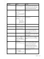
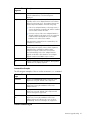
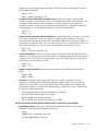
Driver configuration parameters
Parameter
Options
Description
CheckSum =
Default = ON
Enables or disables the transmit and receive
checksum off-loading feature. Checksum is
supported under NetWare 5.x only. If you
want to enable the CheckSum parameter, you
need to load it on the first instance.
Selections are: ON, OFF, Tx,
Rx
Frame = type
Valid types are:
Ethernet_802.2,
Ethernet_802.3, Ethernet_II,
Ethernet_SNAP
Defines the frame type being used by this load
instance. Ethernet_802.2 and Ethernet_II are
the default values.
node =
NNNNNNNNNNNN
Specifies a node address in this field to
override the default Media Access Controller
(MAC) address (also known as the Locally
Administered Address)
name = text
Displays the name assigned to this adapter
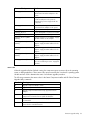
Installation 29
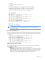
Parameter
Options
Description
PDriver =
Default = OFF
Allows driver to operate in persistent driver
mode. Persistent driver mode is supported
under NetWare 5.x only. Use only if adapter
is placed in a Hot Plug PCI slot and only if
required to swap with an exact board.
Selections are: OFF, ON
RxBuffers =
Default = 200
Recommended Min = 32
Pre-allocates ECB resources on the adapter for
receiving packets
Max = 512
Min = 1 when used with DOS
Client32 and when Keywrod
P3-1 or 2.
TxDescriptors =
Default = 200
Recommended Min = 100
Pre-allocates ECB resources on the adapter for
transmitting packets.
Max = 512
Min = 1 when
used with DOS
Client32 and when
Keywrod P3-1 or
2.
RxFlow =
Default = OFF
Allows enabling/disabling of RxFlow control.
Selections are: ON, OFF
TxFlow =
Default = OFF
Allows enabling/disabling of TxFlow control.
Selections are: ON, OFF
Slot = n
Identifies the slot number for the specific
adapter currently being configured. This
parameter is not necessary if only a single
adapter is installed.
Speed = n
If link negotiation has been disabled, specifies
port speed to be either Auto, 10HD or 10FD,
100HD or 100FD.
Jumbo =
Set maximum physical receive
packet Size = 18000 in the
STARTUP.NCF. Choices are
Jumbo = 1514–9000. This
keyword is only supported on
NetWare 6.x.
Link=
Default=FORCE
Only used to allow the adapter to negotiate a
Selections are: AUTO, FORCE specific or forced line speed with a switch that
is not forced, but instead setup for autonegotiation. It is best to allow for autonegotiation of the card and switch by not
setting this keyword or the speed keyword.
Only use this keyword if the speed keyword is
set to something other than AUTO.
RxTicks=
Default = 360
Min = 0, disabled
Enables/disables Jumbo Frame support. When
enabled, jumbo packets of up to 9000 bytes
are supported. Not supported on NC1020
adapters.
Enables the use of batching receives within a
specific time period.
Max = 5000000, 5 seconds
Units are in micro seconds
Installation 30
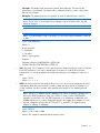
Parameter
Options
Description
TXPacketsPer
Default = 64
Enables the use of batching transmits to a
specific amount of packets.
Min = 0, disabled
Max = 100
NOTE: With Jumbo Frames, the first frame must be Ethernet_ii.
Post installation
After NetWare 6.x has been successfully installed, set the minimum packet receive buffers parameter in
the startup.ncf file to 1500 for each adapter in the system. Set the maximum packet receive buffers to
three times the minimum packet receive buffers. Typically one MB of RAM is required per 1000 receive
buffers. For more information, refer to the "Configuring Driver Parameters" section.
In the autoexec.ncf file, delete the packet receive buffers parameter (RxBuffers=32) in the load
statement for this adapter. Deleting the receive buffers phrase from the load statement resets the receive
buffers parameter to the default value of 200 for this adapter.
NOTE: You must reboot the server for the new configuration.
Example:
The default maximum number of receive buffers for the system is 500; the default minimum is 128. Edit
the startup.ncf file to have the following entries. The actual numbers will be a function of the number of
adapters in the system.
•
set maximum packet receive buffers = 30000
•
set minimum packet receive buffers = 10000
•
set maximum physical receive packet size = 2048
Verifying or modifying adapter properties
When an adapter configuration is saved, the NetWare install program adds load and bind statements to
the autoexec.ncf file. By accessing this file, you can verify the parameters configured for each
adapter, modify them, or enter additional parameters.
NOTE: The Novell monitor program and the CONFIG command are also useful for verifying
driver configuration. For information on how to use these programs, refer to the utilities
reference in your Novell NetWare online documentation.
The parameters that can be defined in the load statements are described in NetWare server driver LOAD
line parameters for HP server adapters below. A valid autoexec.ncf file is shown below. One set of load
and bind commands is added for each frame type the adapter is configured to support.
Valid Autoexec.ncf file
Set Time Zone = PST8PDT
set Daylight Savings Time Offset = 1
set Start Of Daylight Savings Time = (APRIL SUNDAY FIRST 2:00:00 AM)
set End Of Daylight Savings Time = (OCTOBER SUNDAY LAST 2:00:00 AM)
set Default Time Server Type = SINGLE
set Bindery Context = O=LAN
Installation 31
# WARNING!!
file server name NOVELLSERVER51
# WARNING!!
# If you change the name of this server, you must update
# all the licenses that are assigned to this server. Using
# NWAdmin, double-click on a license object and click on
# the Certificate Assignments button. If the old name of
# this server appears, you must delete it and then add the
# new server name. Do this for all license objects.
ServerID 1C8EE2C
LOAD ODINEB.NLM
LOAD TCPIP
LOAD Q57 SLOT=2 FRAME=Ethernet_802.2 NAME=Q57_1_E82
BIND IPX Q57_1_E82 NET=FAFD3D25
LOAD Q57 SLOT=2 FRAME=Ethernet_802.3 NAME=Q57_1_E83
BIND IPX Q57_1_E83 NET=5A2D8D6D
LOAD Q57 SLOT=2 FRAME=Ethernet_SNAP NAME=Q57_1_ESP
BIND IPX Q57_1_ESP NET=477A35BD
LOAD Q57 SLOT=2 FRAME=Ethernet_II NAME=Q57_1_EII
BIND IPX Q57_1_EII NET=C3C8F2E4
BIND IP Q57_1_EII ADDR=172.16.1.1 MASK=ff.ff.0.0
mount all
SEARCH ADD SYS:\JAVA\BIN
SEARCH ADD SYS:\JAVA\NWGFX
IMPORTANT: If you modify any adapter parameters, you must reboot the system before the
changes will take effect. If you make changes and do not reboot, you may experience
configuration problems.
Removing drivers from Autoexec.ncf
To remove the drivers from the Autoexec.ncf, locate the LOAD and BIND command lines associated with
the driver and remark them out by inserting the pound (#) symbol at the beginning of each command line.
Example:
# LOAD Q57 SLOT=2 FRAME=Ethernet_802.2 NAME=Q57_1_E82
# BIND IPX Q57_1_E82 NET=FAFD3D25
# LOAD Q57 SLOT=2 FRAME=Ethernet_802.3 NAME=Q57_1_E83
# BIND IPX Q57_1_E83 NET=5A2D8D6D
# LOAD Q57 SLOT=2 FRAME=Ethernet_SNAP NAME=Q57_1_ESP
# BIND IPX Q57_1_ESP NET=477A35BD
# LOAD Q57 SLOT=2 FRAME=Ethernet_II NAME=Q57_1_EII
# BIND IPX Q57_1_EII NET=C3C8F2E4
# BIND IP Q57_1_EII ADDR=172.16.1.1 MASK=ff.ff.0.0
NetWare server driver LOAD line parameters
This following lists the NetWare server driver LOAD line parameter settings for HP server adapters for
N100, N1000, and N1000e.
•
FORCEDUPLEX. This keyword specifies one of the following duplex modes:
o
Auto-negotiate. The adapter negotiates with the switch and hub how to send and receive packets
at either full- or half-duplex speed. If unsuccessful at negotiating the duplex, HP server adapters
default to half-duplex. You must have an auto-negotiating switch/hub (an Nway switch) to get
full-duplex support with the FORCEDUPLEX parameter set to 0 (auto-negotiation).
Installation 32
o
Full-duplex. The adapter sends and receives packets at the same time. This improves the
performance of your adapter. Set duplex mode to full-duplex ONLY if you have a hub/switch
that supports full-duplex.
o
Half-duplex. The adapter performs one operation at a time. It either transmits or receives.
NOTE: The HP NC31xx, 340T, and NC71xx Server Adapters support full-duplex and halfduplex. The HP NC61xx fiber Gigabit Server Adapters support full-duplex mode only and
cannot be changed.
NOTE: The NC3133 default to full-duplex.
NOTE: To set the adapter to half- or full-duplex, you must set the SPEED parameter to either 10
or 100.
o
Syntax: FORCEDUPLEX=n
Where n =
0—auto-negotiate
1—half-duplex
2—full-duplex
o
Default = auto-negotiate
o
Examples:
100 Mbps full-duplex FORCEDUPLEX=2 SPEED=100
10 Mbps full-duplex FORCEDUPLEX=2 SPEED=10
•
SLOT. (Required) For PCI adapters, SLOT is derived from bus number and device location as defined
by the PCI specification. One way to determine the slot number is to load the driver from the
command line. You will be prompted with valid device number(s) for the adapter(s). Select one of
them.
o
Syntax: SLOT=n
Where n = 1, 2, 3, 4,...
•
SPEED. This keyword specifies the speed the driver uses. If you do not use this parameter, the driver
automatically detects the network speed. If unable to detect, the driver defaults to 10 Mbps. If you
use this parameter, the driver operates at the specified speed instead of auto detecting network
speed.
NOTE: The NC3133 adapter supports 100 Mbps only. It does not default to 10 Mbps. You
must set the SPEED parameter to either 10 or 100 if you want to set the FORCEDUPLEX
parameter to either half or full. The SPEED parameter is for N100.LAN, N1000.LAN, and
N1000e.LAN drivers. You cannot change the speed for the Gigabit (fiber) adapters. You can,
however, change the speed for the NC7170, NC7131, and NC7132 Gigabit (copper)
adapters to 10 Mbps or 100 Mbps.
o
Syntax: SPEED=n
Where n = 10 or 100 or 1000
o
Default = The adapter automatically detects network speed.
Installation 33
•
NODE. This keyword specifies a locally administered address (LAA) unique to each adapter. Use this
option to provide your own unique node address for the adapter. The node address is a 12-digit
hexadecimal number. The second digit must be one of the following digits: 2, 6, A, E.
o
Syntax: NODE=xnxxxxxxxxxx
Where n = 2, 6, A, E
Where x = hexadecimal number
o
•
Default = The adapter's assigned address
FRAME. This keyword indicates one of four valid frame types the system is transmitting and receiving.
o
Syntax: FRAME=n
Where n = Ethernet_802.2, Ethernet_802.3, Ethernet_II, Ethernet_SNAP
o
•
Default = Ethernet_802.2
POLL. This keyword is used to enable polling mode in the driver with interrupt backup. If polling is
enabled, interrupts will be reduced, allowing the processor to spend more time performing other
functions. In polling mode, interrupts will occur only when receive resources have been reduced to
less than half. If polling is not enabled, the driver will perform in traditional interrupt mode.
o
Syntax: POLL=n
o
Where n = 0 (interrupt mode), 1 (polling mode with interrupt backup)
o
Default = 0 (interrupt mode)
NOTE: The POLL parameter is for the N100.LAN, N1000.LAN, and N1000e.LAN drivers.
•
SPURIOUS. This keyword is used to reduce the number of spurious interrupts reported by the OS on
the driver interrupt line. This automatically loads for 10, 100, and 1000 adapters.
o
Syntax: SPURIOUS=n
Where n = 0 or 1
0—Driver operates in normal mode
1—Driver operates to reduce the number of spurious interrupts
o
Default = 1
NOTE: The minimum threshold for acceptable number of spurious interrupts is 200 interrupts
per second, which is the default value of the environmental variable "set display spurious
interrupt alerts threshold."
•
RXCHECKSUM. This keyword is used to enable or disable the offload of Receive Packet Checksum
verification to the adapter. This automatically loads for 10/100 adapters.
o
Syntax: RXCHECKSUM=n
Where n = 0 or 1
0—Does not offload Rx Checksum verification to the adapter
1—Offloads Rx Checksum verification to the adapter
o
Default = 0
NetWare custom statistics
NetWare custom statistics appear when you run monitor NLM and load the LAN driver. One custom
statistic counter is the duplex mode, where 1 = half-duplex and 2 = full-duplex.
Installation 34
The following describes the adapter Status Counters and Software Counters and their acceptable ranges.
N100 custom counters
•
Link Status
This counter contains the link status, as read from the PHY, or general status register of the ASIC. It is
updated once a second. A value of 0 is link up. 1 is link down.
•
Duplex
This counter holds the current duplex as read directly from the PHY, or general status register of the
ASIC. A value of 0 is not supported or unknown, 1 is half-duplex, and 2 is full-duplex. Unsupported
is usually due to an unsupported chip type, or link not being present.
•
Current Speed
This counter holds the current speed as read directly from the PHY, or general status register of the
ASIC. A value of 0 is not supported or not available, 10 for 10 Mbps, 100 for 100 Mbps, and
1000 for 1000 Mbps. Unsupported is usually due to an unsupported chip type, or link not being
present.
•
Hardware Status
A counter of non-zero indicates failure.
•
Tx Good Frames
This counter contains the number of frames that were transmitted properly on the link. It is updated
only after the actual transmission on the link is completed, and not when the frame was read from
memory as is done for the TxCB status. This value varies in accordance to the amount of frames sent,
and can reach billions very quickly.
•
Tx Maximum Collisions
This counter contains the number of frames that were not transmitted because they encountered the
configured maximum number of collisions. This counter increments when the network is heavily
saturated with traffic. If this value is consistently growing, you may want to segment your network
with switches to change the collision domain, so that more time is spent sending data instead of
collisions.
•
Tx Late Collisions
This counter contains the number of frames that were not transmitted because they encountered a
collision outside of the normal collision window. Normally, late collision events should occur only
rarely, if at all. A high number of late collisions is often a sign that there is some problem with the
network topology. Check the topology to be sure that all cables meet IEEE specifications (Category 5
for 100 Mbps TX), and that all distance requirements for cabling are met. Also, check to be sure that
all of the network hubs and switches are configured for the proper duplex mode.
•
Tx DMA Underruns
This counter contains the number of frames that were either not transmitted or re-transmitted due to a
Tx DMA under-run. If the device is configured to retransmit on under-run, this counter may be
updated multiple times for a single frame. Under-runs occur because a lack of PCI bandwidth
resulted in the device's internal transmit FIFO running dry during the transmission of a frame. The
adaptive algorithms within the software keep this number under control. If a high number of underruns are seen, you may want to load the driver with TxThreshold=200 on the command line.
Example:
Load N100 slot=2 Frame=Ethernet_802.2 TxThreshold=200
For additional information about the adaptive algorithm, refer to the "CurrentThreshold" section.
Installation 35
•
Tx Lost Carrier Sense
This counter contains the number of frames that were transmitted by the device despite the fact that it
detected the de-assertion of Carrier Sense during the transmission.
•
Tx Frames Deferred
This counter contains the number of frames that were deferred before transmission due to activity on
the link. This is a normal condition in busy conditions, and the number can grow quite large.
•
Tx OK with Single Collisions
This counter contains the number of transmitted frames that encountered one, and only one, collision
before being successfully sent. This is a normal condition in busy conditions. If single collisions
accumulate quickly, you may want to consider segmenting your network more. To combat collisions,
the software can adjust the interframe gap to allow more room between frames. More room between
frames allows more frames on average. Refer to the "CurrentIFSValue" section for more details.
•
Tx OK with Multiple Collisions
This counter contains the number of transmitted frames that encountered more than one collision. This
only gets incremented once, even though one frame may have had several collisions before being
successfully sent. This is a normal condition in busy conditions. If multi-collisions accumulate quickly,
you may want to consider segmenting your network more. To find the average number of multicollisions a frame had to endure before being successful, use the following formula:
(TxTotalCollisions - TxSingle Collisions - TxMaxCollisions) / TxMultiple Collisions
If the average is close to 16 (the Ethernet max collisions before a frame will no longer be retried),
then you will need to segment your network to avoid losing frames and network efficiency to
collisions.
•
Tx Total Collisions
This counter contains the total number of collisions that were encountered while attempting to
transmit. This count includes late collisions and collisions from frames that encountered
MAXCOL(16). If this counter is growing quickly, you need to segment your network more.
•
Rx Good Frames
This counter contains the number of frames that were received properly from the link. It is updated
only after the actual reception from the link is completed and all the data bytes are stored in
memory.
•
Rx Crc Errors
This counter contains the number of aligned frames discarded because of a CRC error. The
CRC_ERRORS counter is mutually exclusive to the ALIGNMENT_ERRORS and SHORT_FRAMES
counters. CRC errors are usually caused by late collisions where another station has sent data in the
middle of a frame. This number should be very low.
•
Rx Alignment Errors
This counter contains the number of frames that are both mis-aligned (not an even length) and
contain a CRC error. The ALIGNMENT_ERRORS counter is mutually exclusive to the CRC_ERRORS
and SHORT_FRAMES counters.
•
Rx No Resource Errors
This counter contains the number of good frames discarded because there were no resources
available. Frames intended for a host whose Receive Unit is in the "No Resources" state fall into this
category. The number of resource errors can be reduced by increasing the number of receive buffers
Installation 36
that software uses, or increasing the performance of the host machine's processing power (which
would allow for faster processing of the resources).
•
Rx DMA Overrun Errors
This counter contains the number of frames known to be lost because the device's internal receive
FIFO overflowed. This can occur if the device is unable to get the necessary bandwidth on the system
(PCI) bus. If the overflow condition persists for more than one frame, the frames that follow the first
could also be lost. However, because there is no lost frame indicator they may not be counted. A
frame that was counted as an overrun will not be counted in other error counters (SHORT_FRAMES,
CRC_ERRORS, or ALIGNMENT_ERRORS). To combat this, a faster bus machine, or fewer devices on
the bus will be needed.
•
Rx Collisions Detect Errors
This counter contains the number of frames that encountered collisions during frame reception.
•
Rx Short Frame Errors
This counter contains the number of received frames that are shorter than the minimum frame length.
The SHORT_FRAMES counter is mutually exclusive to the ALIGNMENT_ERRORS and CRC_ERRORS
counters and has a higher priority (a short frame will always increment only the SHORT_FRAMES
counter).
•
Flow Control TX Pause
This counter contains Xon and Xoff frames transmitted.
•
Flow Control RX Pause
This counter contains Xon and Xoff frames received.
•
Flow Control Unsupported
This counter contains the MAC Control frames received that are not Flow Control Pause frames.
These frames contain the predefined MAX control type value but contain an unsupported opcode.
•
TCO Rx (or Tx) Frames
This counter is incremented at each received/transmitted TCO packet.
•
Tx Timeouts
This is a debug timer and not currently used. It should be zero.
•
Tx Dynamic Chaining Count
This is a performance evaluation counter and not currently used. It should be zero.
•
Current IFS Value
This is the current Inter Frame Spacing (IFS) value that the driver is using. IFS is an Ethernet
specification term for clock time spaces between frames sent by an individual card in a burst.
Normally a card sends frames back to back with only the minimum frame spacing between each
frame. Under low load conditions, this produces maximum throughput. But under heavy load
conditions, this means less time for other stations to send safely; thus, more collisions and less
throughput.
By adaptively controlling the IFS, more stations can safely send, lowering collisions and helping to
keep throughput high. The larger this number is, the more collisions your network is experiencing.
•
Current Threshold
As under-runs occur, the software can change the amount of time the hardware will wait before
starting to transfer data onto the adapter's hardware buffers. By doing so, it can slow or stop the
Installation 37
amount of under-runs. The higher this number, the more time the adapter is waiting before starting to
transmit data onto the wire. Poor bus performance, large amounts of traffic or a large number of
devices on the same bus can cause this to rise. If this number is always above 170, you may want to
consider loading the driver with the TxThreshold parameter set to a higher value, such as 200.
•
RstartCnt
Re-Start Count, also known as RSC, is a support counter to see how often the restart effort occurs.
Under some high traffic, or high utilization conditions, the receiving unit does not start normally and
needs a restart. RSC has no impact on the end user. It is intended for software development use
only. It is normal for this to be non-zero.
•
REC
Under some busy conditions, the receiving unit stalls and needs to be restarted. This counter tracks
the number of times it needs to be restarted. RSC is a subset of REC. Most REC events restart
normally, but the few that do not are REC events. This counter is intended for software development
use only and may be disregarded by the end user. It is normal for this to be non-zero.
•
Checksum Good
This counter indicates the number of received packets that the hardware has verified, the checksum,
and if the checksum is valid.
•
Checksum Bad
This counter indicates the number of received packets that the hardware has verified, the checksum,
and if the checksum is valid.
•
Stalled Ints SW Resets
This counter indicates the number of times the driver issued a complete reset (to the driver and to the
adapter) as a result of a stalled interrupt situation. A stalled interrupt situation is detected by the
driver if there are no interrupts for a long time, and a SW interrupt issued by the driver fails to
arrive.
•
Carrier Loss PHY Resets
This counter indicates the number of times the driver reset the PHY as a result of carrier sense loss.
N1000 and N1000e custom counters
•
Duplex Mode (1=Half, 2=Full)
This counter indicates the current link duplex configuration. A value of 1 indicates the adapter is
configured to half-duplex mode. A 2 indicates full-duplex mode configuration. This counter exists in
v1.12 or higher of the NetWare server driver.
•
Line Speed (Mbps)
This counter displays the current line speed in Mbps.
•
Configured Duplex Mode (0=Auto, 1=Half, 2=Full)
•
Configured Speed (Mbps; 0=Auto)
•
PCI Mode (0=PCI, 1=PCI-x, 2=PCI-Express)
•
Bus Clock Rate (Mhz) (0=Unavailable)
•
Link Status (0=Up, 1=Down)
This counter describes the current link status of the adapter. A value of 0 indicates the link is up and
a value of 1 indicates that the link is down. This counter exists in v1.12 or higher of the NetWare
server driver.
Installation 38
•
Link Status Change Count
This counter indicates the number of times the link status has been changed.
•
Rx CRC Error Count
This counter indicates the number of receive packets with CRC errors. Packets less than 64 bytes are
not counted in this statistic.
•
Alignment Errors
This counter holds the number of receive packets with alignment errors. In order for a packet to be
counted, it must pass address filtering and must be 64 bytes or greater in length. If receives are not
enabled, then this counter does not increment. This counter is valid only in MII mode during 10/100
Mbps operation.
•
Rx Symbol Error Count
This counter indicates the number of symbol errors between reads. The count increases for every bad
symbol received, whether or not a packet is currently being received and whether or not the link is
up. This counter will increment along with the Rx Sequence Error Count when either the fiber cable is
disconnected or the connector is not seated completely. Also, during driver load, this counter will
increments minimally.
•
Rx Error Count
This counter indicates the number of packets received in which I_RX_ER was asserted by the PHY. In
order for a packet to be counted, it must pass address filtering and must be 64 bytes or greater
(from <Destination Address> through <CRC>, inclusively) in length. If receives are not enabled, then
this counter does not increment. In TBI mode, this counter increments on the reception of /V/ codes.
•
Rx Missed Packets Count
This counter indicates the number of missed packets. Packets are missed when the hardware receive
FIFO has insufficient space to store the incoming packet. This could be the result of having too few
buffers allocated or because there is insufficient bandwidth on the IO bus. These packets are also be
counted in the Total Packets Received counter as well as in Total Octets Received.
•
Tx Single Collision Count
This counter indicates the number of times that a transmitted packet encountered a single collision.
This counter increments only if the device is in half-duplex mode.
•
Tx Excessive Collisions Count
This counter indicates when 16 or more collisions have occurred on a packet. This counter
increments only if the device is in half-duplex mode.
•
Tx Multiple Collision
This counter indicates the number of times that a transmitted packet encountered more than one
collision but less than 16. This counter increments only if the device is in half-duplex mode.
•
Tx Late Collisions Count
This counter indicates collisions that occur after 512 bit (64 byte) times. This counter increments only
if the device is in half-duplex mode.
•
Tx TOTAL Collision
This counter indicates the total number of collisions seen by the transmitter. This counter increments
only if the device is in half-duplex mode.
•
Tx DMA Underruns
Installation 39
This counter contains the number of frames that were either not transmitted or re-transmitted due to a
Tx DMA under-run. If the device is configured to retransmit on under-run, this counter may be
updated multiple times for a single frame. Under-runs occur because a lack of PCI bandwidth
resulted in the device's internal transmit FIFO running dry during the transmission of a frame. The
adaptive algorithms within the software keep this number under control. To see how the adaptive
algorithm is doing, refer to the "Current Threshold" section.
•
Tx Defer Count
This counter indicates transmit defer events. A defer event occurs when the transmitter cannot
immediately send a packet due to the medium being busy, either because another device is
transmitting or the link is not up.
•
Tx with No CRS
This counter counts the number of successful packet transmissions in which the Carrier Sense input
from the PHY was not asserted within one slot time of start of transmission. The PHY should assert
Carrier Sense during every transmission. Failure to do so may indicate that the link has failed, or the
PHY has an incorrect link configuration. This counter is not valid in TBI mode, and is only valid when
the device is operating at full-duplex.
•
Rx Sequence Error Count
This counter indicates receive sequence error events. This counter increments along with the Rx
Symbol Error Count when either the fiber cable is disconnected or the connector is not seated
completely.
•
Rx Length Error Count
This counter indicates receive length error events. A length error occurs if an incoming packet is
undersized (less than 64 bytes) or oversized (greater than 1522).
•
Rx DMA Too Early
This counter counts the total number of times that the device attempted to perform an Early DMA
operation (by speculatively requesting the host bus prior to reception of the entire packet) and ran
out of data to DMA before the device was forced to relinquish ownership of the bus. This condition is
really not an "error" condition, but is nevertheless counted for diagnostic purposes. This statistic is
valid only if Early Receives are enabled.
•
XON Received Count
This counter indicates the number of XON packets received. XON packets can occur when Flow
Control is enabled and both the adapter and its link partner are configured to use it.
•
XON Transmitted Count
This counter indicates the number of XON packets transmitted. XON packets can occur when Flow
Control is enabled and both the adapter and its link partner are configured to use it.
•
XOFF Received Count
This counter indicates the number of XOFF packets received. XOFF packets can occur when Flow
Control is enabled and both the adapter and its link partner are configured to use it.
•
XOFF Transmitted Count
This counter indicates the number of XOFF packets transmitted. XOFF packets can occur when Flow
Control is enabled and both the adapter and its link partner are configured to use it.
•
Flow Control Received Unsupported Count
Installation 40
This counter indicates the number of unsupported flow control frames that are received. This counter
increments when a flow control packet is received which does not match the adapter definition of a
flow control packet. This counter is not expected to increment.
•
64 Byte Packets Received
This counter indicates the number of good packets received that are exactly 64 bytes in length,
including CRC. Packets counted in the Missed Packet Count are not counted here. This counter does
not include received flow control packets.
•
65–127 Byte Packets Received
This counter indicates the number of good packets received that are 65–127 bytes in length,
including CRC. Packets counted in the Missed Packet Count are not counted here. This counter does
not include received flow control packets.
•
128–255 Byte Packets Received
This counter indicates the number of good packets received that are 128–255 bytes in length,
including CRC. Packets counted in the Missed Packet Count are not counted here. This counter does
not include received flow control packets.
•
256–511 Byte Packets Received
This counter indicates the number of good packets received that are 256–511 bytes in length,
including CRC. Packets counted in the Missed Packet Count are not counted here. This counter does
not include received flow control packets.
•
512–1023 Byte Packets Received
This counter indicates the number of good packets received that are 512–1023 bytes in length,
including CRC. Packets counted in the Missed Packet Count are not counted here. This counter does
not include received flow control packets.
•
>1024 Byte Packets Received
This counter indicates the number of good packets received that are 1024–1522 bytes in length,
including CRC. Packets counted in the Missed Packet Count are not counted here. This counter does
not include received flow control packets.
•
Good Packets Received Count (Any Length)
This counter indicates the number of good packets received of any legal length. This counter does
not include received flow control packets.
•
Broadcast Packets Received Count
This counter indicates the number of good broadcast packets received.
•
Multicast Packets Received Count
This counter indicates the number of good multicast packets received. This counter does not include
received flow control packets.
•
Good Packets Transmitted Count (Any Length)
This counter indicates the number of good packets transmitted of any legal length. This counter does
not include received flow control packets.
•
Good Octets Received Count LO
This counter, in conjunction with the Good Octets Received Count HI, makes up a 64-bit counter that
indicates the number of good octets received. This statistic reflects the lower 32 bits of the 64-bit
counter. This counter does not include received flow control packets.
Installation 41
•
Good Octets Received Count HI
This counter, in conjunction with the Good Octets Received Count LO, makes up a 64-bit counter
that indicates the number of good octets received. This counter reflects the upper 32 bits of the 64-bit
counter and is incremented each time the Good Octets Received Count LO has reached it maximum
value and wraps to zero. This counter does not include received flow control packets.
•
Good Octets Transmitted Count LO
This counter, in conjunction with the Good Octets Transmitted Count HI, makes up a 64-bit counter
that indicates the number of good octets transmitted. This counter reflects the lower 32 bits of the 64bit counter. This counter does not include received flow control packets.
•
Good Octets Transmitted Count HI
This counter, in conjunction with the Good Octets Transmitted Count LO, makes up a 64-bit counter
that indicates the number of good octets transmitted. This counter reflects the upper 32 bits of the 64bit counter and is incremented each time the Good Octets Transmitted Count LO has reached it
maximum value and wraps to zero. This counter does not include received flow control packets.
•
Receive No Buffers Count
This counter indicates the number of times that packets were received when there were no available
buffers in host memory to store those packets. The packet is still received if there is space in the
hardware FIFO. This counter does not include received flow control packets. Increasing Rx
Descriptors on the command line during load could result in this counter incrementing less frequently.
•
Receive Undersize Count
This counter indicates the number of received packets that were less than minimum size (64 bytes)
and had a valid CRC.
•
Receive Fragment Count
This counter indicates the number of received packets that were less than minimum size (64 bytes)
but had a bad CRC.
•
Receive Oversize Count
This counter indicates the number of received packets that were greater than maximum size (1522
bytes) and had a valid CRC.
•
Receive Jabber Count
This counter indicates the number of received packets that were greater than maximum size (1522
bytes) but had a bad CRC.
•
Total Octets Received LO
This counter, in conjunction with the Total Octets Received HI, makes up a 64-bit counter that
indicates the total number of octets received. This counter reflects the lower 32 bits of the 64-bit
counter.
•
Total Octets Received HI
This counter, in conjunction with the Total Octets Received LO, makes up a 64-bit counter that
indicates the total number of octets received. This counter reflects the upper 32 bits of the 64-bit
counter and is incremented each time the Total Octets Received LO has reached it maximum value
and wraps to zero.
•
Total Octets Transmitted LO
Installation 42
This counter, in conjunction with the Total Octets Transmitted HI, makes up a 64-bit counter that
indicates the total number of octets transmitted. This counter reflects the lower 32 bits of the 64-bit
counter.
•
Total Octets Transmitted HI
This counter, in conjunction with the Total Octets Transmitted LO, makes up a 64-bit counter that
indicates the total number of octets transmitted. This counter reflects the upper 32 bits of the 64-bit
counter and is incremented each time the Total Octets Transmitted LO has reached it maximum value
and wraps to zero.
•
Total Packets Received
This counter indicates the total number of packets received. All packets are counted here, regardless
of their length, whether they are erred, or whether they are flow control packets.
•
Total Packets Transmitted
This counter indicates the total number of packets transmitted. All packets transmitted will be counted
here, regardless of their length or whether they are flow control packets.
•
64 Byte Packets Transmitted
This counter indicates the number of good packets transmitted that are exactly 64 bytes in length,
including CRC. This counter does not include transmitted flow control packets.
•
65–127 Byte Packets Transmitted
This counter indicates the number of good packets transmitted that are 65–127 bytes in length,
including CRC. This counter does not include transmitted flow control packets.
•
128–255 Byte Packets Transmitted
This counter indicates the number of good packets transmitted that are 128–255 bytes in length,
including CRC. This counter does not include transmitted flow control packets.
•
256–511 Byte Packets Transmitted
This counter indicates the number of good packets transmitted that are 256–511 bytes in length,
including CRC. This counter does not include transmitted flow control packets.
•
512–1023 Byte Packets Transmitted
This counter indicates the number of good packets transmitted that are 512–1023 bytes in length,
including CRC. This counter does not include transmitted flow control packets.
•
>1024 Byte Packets Transmitted
This counter indicates the number of good packets transmitted that are 1024–1522 bytes in length,
including CRC. This counter does not include transmitted flow control packets.
•
Broadcast Packets Transmitted Count
This counter indicates the number of good broadcast packets transmitted.
•
Multicast Packets Transmitted Count
This counter indicates the number of good multicast packets transmitted. This counter does not
include transmitted flow control packets.
•
Rx Checksum Good Pkts
This counter indicates the number of receive packets with good checksums calculated. This counter
increments only when RxTcpChecksum has been enabled and packets with good checksums are
received.
•
Rx Checksum Error Pkts
Installation 43
This counter indicates the number of receive packets with CRC errors. Packets less than 64 bytes are
not counted in this counter.
•
Tx Threshold
This counter indicates the current value of the Early Transmit Threshold. The adapter starts
transmitting the packet when the specified number of quad-words has been DMAed in from memory.
•
Current IFS Value
This counter indicates the current value of Inter Frame Spacing between back-to-back transmits.
•
Jumbo Frames Received
This counter indicates the number of jumbo packets received (packets greater than 1514 in length).
•
Jumbo Frames Transmitted
This counter indicates the number of jumbo packets transmitted (packets that are greater than 1514
in length).
•
PCI-X mode (0=PCI, 1=PCI-X)
This counter indicates whether the adapter is in a PCI.
CPQANS custom counters
•
Number of Tx ECBs Queued in Members
This counter indicates the number of packets (Event Control Blocks) that are queued in team members
for transmission.
•
Number of Tx ECBs Queued in Unavailable ECBs Queue
This counter indicates the number of transmit packets (Event Control Blocks) that are currently in the
CPQANS transmit queue.
•
Total Enqueued Tx Due to No Available ECBs
This counter indicates the number of transmit packets that were queued due to no available ECBs.
•
Number of Probes Sent by All Team Members
This counter indicates the number of probe packets sent by all team members.
•
Number of Probes Received by All Team Members
This counter indicates the number of probe packets received by all team members.
Advanced Network Services help - supported keywords
•
•
•
•
AGG_SELECTION
o
Syntax: AGG_SELECTION=[BANDWIDTH | COUNT]
o
Description: Sets active aggregator selection mode by bandwidth or count
BALANCE_INTERVAL
o
Syntax: balance_interval=nnn
o
Description: Changes Balance interval, nnn counts 1/18 sec
BALANCE_SET_DEFAULT
o
Syntax: balance_set_default
o
Description: Restores Balance interval to factory settings
COMMIT
o
Syntax: commit [team=nnn]
Installation 44
o
•
•
DELAY
o
Syntax: delay=nnn
o
Description: Delays the commit in nnn seconds
FRAME
o
•
•
•
•
•
•
•
•
•
Syntax: frame=[ETHERNET_802.2 | ETHERNET_802.3 | ETHERNET_II | ETHERNET_SNAP]
HELP
o
Syntax: -H
o
Description: Displays Help
o
Example: CPQANS -H
JOIN_INDIVIDUALS
o
Syntax: join_individuals=[yes | no]
o
Description: Joins all individual links to one aggregator
LBN
o
Syntax: Reset LBN=nnn
o
Example: cpqans reset lbn=nnn
o
Description: Resets the logical board number (LBN) of a bound adapter. Supported only after
commit command. Default value = 0
MAX_TX_QUEUE
o
Syntax: max_tx_queue=nnn
o
Description: Sets the Max number of TX ECBs queued for send
MODE
o
•
Description: Sets a certain mode. Use after binding to base drivers with Team=nnn.
Syntax: mode=[NFT | ALB | FEC | GEC | 802.3AD]
NAME
o
Syntax: name=[any unique name]
o
Description: Sets a unique name
PRIMARY
o
Syntax: primary | secondary
o
Description: Identifies the primary adapter. Supported only in BIND command
PROBE_BURST_SIZE
o
Syntax: probe_burst_size=nnn
o
Description: Changes number of probes to send in a retry
PROBE_CHECK_INTERVAL
o
Syntax: probe_check_interval=nnn
o
Description: Changes probes check interval
PROBE_RECHECK_INTERVAL
o
Syntax: probe_recheck_interval=nnn
o
Description: Changes probe retries check interval
Installation 45
•
•
•
•
•
•
•
•
•
•
•
•
•
PROBE_RETRY_COUNT
o
Syntax: probe_retry_count=nnn
o
Description: Changes probes retry count
PROBE_SEND_INTERVAL
o
Syntax: probe_send_interval=nnn
o
Description: Changes probes send interval, nnn counts 1/18 sec
PROBE_SET_DEFAULT
o
Syntax: probe_set_default
o
Description: Restores probes settings to factory settings
PROBES
o
Syntax: probes=[on | off]
o
Description: Enables/disables probes
PROBES
o
Syntax: probes=[BROADCAST|MULTICAST]
o
Description: Changes probes addressing
RECOMMIT
o
Syntax: recommit [team=nnn]
o
Description: Resets a certain mode. Use after hot binding to base drivers with Team=nnn
REMOVETEAM
o
Syntax: removeteam [team=nnn]
o
Description: Removes a team. Use after hot binding to base drivers with Team=nnn
REMOVEVLANID
o
Syntax: RemoveVlanID=nnn
o
Description: Removes the selected VLAN
RESET
o
Syntax: RESET LBN=nnn
o
Description: Supported only after Commit command
SECONDARY
o
Syntax: primary | secondary
o
Description: Identifies the secondary adapter. Supported only in BIND command.
SMPMODE
o
Syntax: SMPMODE=[SMP | NONSMP]
o
Description: Enables/disables SMP aware
STATUS
o
Syntax: status [team=nnn]
o
Description: Prints CPQANS status
TEAM
o
Syntax: team=nnnn
Installation 46
o
•
•
Description: Identifies the team. nnnn=DecimalNumber.
TX_ECBS_TO_USE
o
Syntax: tx_ecbs_to_use=nnn
o
Description: Sets number of TX ECBs to allocate per virtual adapter
VLANID
o
Syntax: VlanID=nnn
o
Description: Sets team to VLAN mode. Creates MLID edge
Installation 47
Firmware upgrade utility
In this section
Windows utility ...................................................................................................................................... 48
c-Class BladeSystem utility ....................................................................................................................... 54
Linux utility ............................................................................................................................................ 54
DOS utility............................................................................................................................................. 59
Windows utility
These notes describe how to use the Gigabit Server Adapter Firmware Upgrade Utility to flash server
adapter firmware.
Flashing consists of using software to replace the current server adapter firmware on a target server with
a new firmware image. Server adapter firmware is typically flashed for the following reasons:
•
To support new features
•
To correct problems in a previous server adapter firmware version
Customers should upgrade their servers to the latest server adapter firmware version:
•
When HP releases a new server adapter firmware version
•
When installing a new server adapter
•
After purchasing a new server
•
When installing a SoftPaq that specifies the need for the latest version of firmware
The Gigabit Server Adapter Firmware Upgrade Utility automatically checks for driver, hardware, and
operating system dependencies, and installs only the correct server adapter firmware upgrades required
by each target server.
Supported operating systems
The upgrade utility supports the following operating systems:
•
Microsoft® Windows® 2000 Server
•
Microsoft® Windows® 2000 Advanced Server
•
Microsoft® Windows® 2000 Data Center
•
Microsoft® Windows® 2000 Terminal Server
•
Microsoft® Windows 2003 Server
•
Microsoft® Windows 2003 (32-bit) Enterprise Server
•
Microsoft® Windows 2003 (32-bit) Data Center
•
Microsoft® Windows 2003 (x64) Enterprise Server
Supported Gigabit Server Adapters
The upgrade utility provides support for the following adapters:
Firmware upgrade utility 48
Standup adapters:
•
HP NC150T PCI 4-port Gigabit Combo Switch Adapter
•
HP NC320T PCI Express Gigabit Server Adapter
•
HP NC364T PCI Express Quad Port Gigabit Server Adapter
•
HP NC370T PCI-X Multifunction Gigabit Server Adapter
•
HP NC370F PCI-X Multifunction Gigabit Server Adapter
•
HP NC373F PCI Express Multifunction Gigabit Server Adapter
•
HP NC373T PCI Express Multifunction Gigabit Server Adapter
•
HP NC380T PCI Express Dual Port Multifunction Gigabit Server Adapter
•
HP NC1020 Cu Gigabit Server Adapter 32 PCI Single Port
•
HP NC6770 PCI-X Gigabit Server Adapter
•
HP NC7770 PCI-X Gigabit Server Adapter
•
HP NC7771 PCI-X Gigabit Server Adapter
Embedded adapters:
•
HP NC320i Integrated PCI Express Gigabit Server Adapter
•
HP NC324i Integrated Dual Port PCI Express Gigabit Server Adapter
•
HP NC325i PCI Express Dual Port Gigabit Server Adapter
•
HP NC326i PCI Express Dual Port Gigabit Server Adapter
•
HP NC370i PCI-X Multifunction Gigabit Server Adapter
•
HP NC371i Integrated PCI-X Multifunction Gigabit Server Adapter
•
HP NC373i PCI Express Multifunction Gigabit Server Adapter
•
HP NC7760 PCI-X Gigabit Server Adapter
•
HP NC7761 PCI Gigabit Server Adapter
•
HP NC7780 Gigabit Server Adapter
•
HP NC7781 PCI-X Gigabit Server Adapter
•
HP NC7782 Dual Port PCI-X Gigabit Server Adapter
Mezzanine Adapters:
•
HP NC320m PCI Express Dual Port 1Gb Server Adapter
•
HP NC325m PCI Express Quad Port 1Gb Server Adapter for c-Class BladeSystem
•
HP NC326m PCI Express Dual Port 1Gb Server Adapter for c-Class BladeSystem
•
HP NC373m PCI Express Dual Port Multifunction Gigabit Server Adapter for c-Class BladeSystem
•
HP NC374m PCI Express Dual Port Multifunction Gigabit Server Adapter
IMPORTANT: For each server adapter in the target server, the driver for the adapter must be
installed and enabled for the server adapter to be upgraded. If the driver is unable to
communicate with the server adapter, the server adapter cannot be updated.
Firmware upgrade utility 49
IMPORTANT: Before updating NC6770 or NC7770 server adapters, move jumper J1 to the
Enable position. After updating each server adapter, move jumper J1 to the Disable position.
NOTE: NC6770, NC7770, and NC7780 server adapters require about 15 minutes each to
update both the PXE and Boot Code.
NOTE: To update the PXE code for embedded and mezzanine adapters, update the system
BIOS.
Drivers
For each server adapter in the target server, the driver for the adapter must be installed and enabled for
the server adapter to be upgraded. If the driver is unable to communicate with the server adapter, the
server adapter cannot be updated.
Installing the firmware utility
The HP Network Adapter Online Firmware Upgrade Utility is located in the \apps\fwupgrade\windows
directory obtained by extracting the HP SoftPaq file. Complete the following steps to download and
extract the SoftPaq file.
1.
Go to the HP website (http://www.hp.com).
2.
Click Software & Driver Downloads from the left menu bar.
3.
Type the product name in the For product box and press Enter. For example, type NC370T.
4.
Select an operating system.
5.
Click HP ProLiant Networking Software.
6.
Click download and save the HP SoftPaq (sp#####.exe) file to a directory on your hard drive. The
SoftPaq file is a self-extracting executable with a file name based on the SoftPaq number.
7.
Click the SoftPaq file to extract the files and then open the cmponent.htm file.
The upgrade utility installation is launched by clicking the Smart Component (CPXXXXXX.exe) file
(interactive mode) or by using the command line prompt. The Smart Component for the upgrade utility is
launched using the command line prompt to allow you to pass arguments to alter installation behavior.
Command line syntax
The general command line syntax for the Smart Component installation includes:
CPXXXXXX [/S[ILENT]] [/F[ORCE]] [/R[EBOOT]] [/H[ELP]] [/?]
CPXXXXXX is the command that launches the Smart Component on the target server. The six X's represent
the serialized number assigned to the component.
Command line arguments
The Smart Component recognizes the following command line arguments. Smart Components are not
case-sensitive.
NOTE: All arguments and information enclosed in brackets are optional.
Firmware upgrade utility 50
Command line
argument
Description
/S[ILENT]
Supresses console messages. If this argument is omitted
from the command line, console messages are
displayed.
/F[ORCE]
Specifies whether an installation will be forced,
regardless of the server adapter firmware version that is
detected on the target server. The argument changes the
Smart Component installation in the following ways:
•
If the server adapter firmware on the target server is
current, the firmware reinstalls itself, and the installed
version number remains the same.
•
If a newer version of the server adapter firmware is
already installed on the target server, the component
installs itself and downgrades the server adapter
firmware to the older version number.
If this argument is omitted from the command line, the
installation is not forced.
/R[EBOOT]
Specifies whether the target server will reboot if the
Smart Component requests a reboot. If this argument is
omitted from the command line and the Smart
Component requests a reboot, the server must be
rebooted manually for the server adapter firmware
upgrade to take effect. The Windows server adapter
upgrade component will NOT request a reboot.
/H[ELP]
Displays command line Help information.
/?
Displays command line Help information. This argument
is identical to the /H[ELP] argument.
Command Line Examples
The following are examples of how to use the CPXXXXXX.exe command.
Command line
input
Result
CPXXXXXX
Deploys the CPXXXXXX.EXE Smart Component on the
target server using the defaults of the component.
CPXXXXXX /F
Deploys the CPXXXXXX.EXE Smart Component on the
target server, forcing the installation of the server
adapter firmware.
CPXXXXXX /S
Deploys the CPXXXXXX.EXE Smart Component on the
target server using the defaults of the component. All
console messages are suppressed.
CPXXXXXX /S /F
/R
Deploys the CPXXXXXX.EXE Smart Component on the
target server, forcing the installation of the server
adapter firmware and allowing the server to reboot
automatically. All console messages are suppressed.
Common installation log file
Firmware upgrade utility 51
The upgrade installation activity (including errors) is written by the Smart Component to a common
installation log file called CPQSETUP.LOG in the \CPQSYSTEM\LOG subdirectory on the target server.
Information regarding subsequent installation activity is appended to the same log file, which provides a
chronological history of all component installation activity on the target server.
Using the NicFwUpg.exe command line interface
It is possible to launch the HP Online Firmware Upgrade Utility by clicking the executable file during
installation or by using the command line interface. The following information describes how to launch the
utility using the command line interface.
Command line syntax
The utility supports the following commands:
Command Line Input
Result
nicfwupg.exe -c
Displays the current firmware version of all
HP NC-Series Broadcom adapters in the
system
nicfwupg.exe -l
Displays the latest version of HP NC-Series
Broadcom adapters in the system as
determined by versions shipped with the
component.
nicfwupg.exe -a
Retuns the saved image version of HP NCSeries Broadcom adapters in the system
nicfwupg.exe -s
Suppresses console output
nicfwupg.exe -f
Forces downgrades or restores as needed
nicfwupg.exe -p
Requests a restore on all adapters
nicfwupg.exe -e [MAC Address]
Requests a restore on one adapter. Supply
the MAC address for the adapter.
nicfwupg.exe -o [MAC Address]
Performs an upgrade of boot code for one
adapter. Supply the MAC address for the
adapter.
nicfwupg.exe -x [MAC Address]
Performs an upgrade of PXE for one
adapter. Supply the MAC address for the
adapter.
nicfwupg.exe -b [MAC Address]
Performs an upgrade of CLP for one
adapter. Supply the MAC address for the
adapter.
nicfwupg.exe -i [filename]
Performs an upgrade and stores the image
file to be used during a restore. Supply the
filename.
Using the nicfwup_mf.exe command line interface
It is possible to launch the HP Online Firmware Upgrade Utility for Multifunction adapters by clicking the
executable file during installation or by using the command line interface. The following information
describes how to launch the utility for Multifunction network adapters using the command line interface.
Command line syntax
The utility supports the following commands:
Firmware upgrade utility 52
Command Line Input
Result
nicfwupg_mf.exe -c
Displays the current firmware version of all
HP NC-Series Broadcom adapters in the
system
nicfwupg_mf.exe -l
Displays the latest version of HP NC-Series
Broadcom adapters in the system as
determined by versions shipped with the
component.
nicfwupg_mf.exe -a
Retuns the saved image version of HP NCSeries Broadcom adapters in the system
nicfwupg_mf.exe -s
Suppresses console output
nicfwupg_mf.exe -f
Forces downgrades or restores as needed
nicfwupg_mf.exe -p
Requests a restore on all adapters
nicfwupg_mf.exe -e [MAC
Address]
Requests a restore on one adapter. Supply
the MAC address for the adapter.
nicfwupg_mf.exe -o [MAC
Address]
Performs an upgrade of boot code for one
adapter. Supply the MAC address for the
adapter.
nicfwupg_mf.exe -x [MAC
Address]
Performs an upgrade of PXE for one
adapter. Supply the MAC address for the
adapter.
nicfwupg_mf.exe -b [MAC
Address]
Performs an upgrade of CLP for one
adapter. Supply the MAC address for the
adapter.
nicfwupg_mf.exe -i [filename]
Performs an upgrade and stores the image
file to be used during a restore. Supply the
filename.
Return codes
When the upgrade utility has finished running, the component reports a return code to the operating
system or calling application. These return codes are processed by the %errorlevel% operating system
variable and are used to determine the status of a firmware upgrade procedure.
The following summarizes the return codes for the Smart Component installer and HP Online Firmware
Upgrade Utility commands.
Error level
Meaning
0
Upgrade component failed to install
1
Upgrade component installed successfully
3
Upgrade component did not detect any supported network
adapters
4
Firmware upgrade was recommended, but the upgrade
component was instructed to not update the firmware
5
All firmware versions are current and an upgrade is not
recommended
6
At least one network adapter has firmware installed that is
newer than the available firmware.
Firmware upgrade utility 53
c-Class BladeSystem utility
The HP Gigabit Server Adapter Firmware Upgrade Utility for c-Class BladeSystem uses two separate
utilities (ccfwupg1.bat and ccfwupg2.bat) to upgrade firmware on the c-Class BladeSystem adapters.
The ccfwupg1.bat command upgrades the Boot Code and Option ROM firmware image on the following
c-Class Multifunction Gigabit Server Adapters:
•
HP NC373i Multifunction Gigabit Server Adapter
•
HP NC373m Multifunction Gigabit Server Adapter
The ccfwupg2.bat command upgrades the Boot Code and Option ROM firmware image on the following
c-Class Gigabit Server Adapters:
•
HP NC326i PCIe Dual Port Gigabit Server Adapter
•
HP NC326m PCIe Dual Port Gigabit Server Adapter
•
HP NC325m PCIe Quad Port Gigabit Server Adapter
Upgrading firmware
To upgrade the boot code and Option ROM image on the adapter, complete the following:
1.
Go to the HP website (http://www.hp.com).
2.
Click Software & Driver Downloads from the left menu bar.
3.
Type the product name in the For product box and press Enter. For example, type NC370T.
4.
Select an operating system.
5.
Click HP ProLiant Networking Software.
6.
Click download and save the HP SoftPaq (sp#####.exe) file to a directory on your hard drive. The
SoftPaq file is a self-extracting executable with a file name based on the SoftPaq number.
7.
Click the SoftPaq file to extract the files and then open the cmponent.htm file.
8.
Copy all files and folders from the \apps\ccfwupg\ccfwupg1 directory or the
\apps\ccfwupg\ccfwupg2 directory to a bootable diskette or USB drive.
9.
Boot to DOS using the diskette for your adapter.
10.
Type ccfwupg1.bat or ccfwupg2.bat and press the Enter key. A confirmation message displays when
the upgrade is complete.
Linux utility
The following information describes how to use the Linux Gigabit Server Adapter Firmware Upgrade
Utility to flash server adapter firmware.
Supported operating systems
The firmware upgrade utility supports the following Linux operating systems:
Linux 32
•
Red Hat Enterprise Linux 4
•
Red Hat Enterprise Linux 5
•
SUSE Linux Enterprise Server 10 x86
Firmware upgrade utility 54
•
SUSE Linux Enterprise Server 9 x86
Linux 64
•
Red Hat Enterprise Linux 4 for AMD64 and Intel EM64T
•
Red Hat Enterprise Linux 5 for AMD64 and Intel EM64T
•
SUSE Linux Enterprise Server 10 for AMD64 and Intel EM64T
•
SUSE Linux Enterprise Server 9 for AMD64 and Intel EM64T
For a complete listing refer to the Linux Readme file located in the HP SoftPaq file.Complete the following
steps to download and extract the SoftPaq file.
1.
Go to the HP website (http://www.hp.com).
2.
Click Software & Driver Downloads from the left menu bar.
3.
Type the product name in the For product box and press Enter. For example, type NC370T.
4.
Select an operating system.
5.
Click HP ProLiant Networking Software.
6.
Click download and save the HP SoftPaq (sp#####.exe) file to a directory on your hard drive. The
SoftPaq file is a self-extracting executable with a file name based on the SoftPaq number.
7.
The hpnicfwupg Linux online firmware upgrade utility is located in the apps\fwupgrade\linux folder.
Supported Gigabit Server Adapters
The upgrade utility provides support for the following adapters:
Standup adapters:
•
HP NC150T PCI 4-port Gigabit Combo Switch Adapter
•
HP NC320T PCI Express Gigabit Server Adapter
•
HP NC370T PCI-X Multifunction Gigabit Server Adapter
•
HP NC370F PCI-X Multifunction Gigabit Server Adapter
•
HP NC373F PCI Express Multifunction Gigabit Server Adapter
•
HP NC373T PCI Express Multifunction Gigabit Server Adapter
•
HP NC380T PCI Express Dual Port Multifunction
•
HP NC1020 Cu Gigabit Server Adapter 32 PCI Single Port
•
HP NC6770 PCI-X Gigabit Server Adapter
•
HP NC7770 PCI-X Gigabit Server Adapter
•
HP NC7771 PCI-X Gigabit Server Adapter
Embedded adapters:
•
HP NC320i PCI Express Gigabit Server Adapter
•
HP NC324i PCI Express Dual Port Gigabit Server Adapter
•
HP NC326i PCI Express Dual Port Gigabit Server Adapter
•
HP NC370i PCI-X Multifunction Gigabit Server Adapter
•
HP NC371i PCI-X Multifunction Gigabit Server Adapter
•
HP NC373i PCI Express Multifunction Gigabit Server Adapter
Firmware upgrade utility 55
•
HP NC7760 PCI-X Gigabit Server Adapter
•
HP NC7761 PCI Gigabit Server Adapter
•
HP NC7780 Gigabit Server Adapter
•
HP NC7781 PCI-X Gigabit Server Adapter
•
HP NC7782 Dual Port PCI-X Gigabit Server Adapter
Mezzanine Adapters:
•
HP NC320m PCI Express Dual Port Gigabit Server Adapter
•
HP NC325m PCI Express Quad Port 1Gb Server Adapter for c-Class BladeSystem
•
HP NC326m PCI Express Dual Port 1Gb Server Adapter for c-Class BladeSystem
•
HP NC373m PCI Express Dual Port Multifunction Gigabit Server Adapter for c-Class BladeSystem
•
HP NC374m PCI Express Dual Port Multifunction Gigabit Server Adapter
IMPORTANT: For each server adapter in the target server, the driver for the adapter must be
installed and enabled for the server adapter to be upgraded. If the driver is unable to
communicate with the server adapter, the server adapter cannot be updated.
IMPORTANT: Before updating NC6770 or NC7770 server adapters, move jumper J1 to the
Enable position. After updating each server adapter, move jumper J1 to the Disable position.
NOTE: NC6770, NC7770, and NC7780 server adapters require about 15 minutes each to
update both the PXE and Boot Code.
NOTE: To update the PXE code for embedded and mezzanine adapters, update the system
BIOS.
Drivers
For each server adapter in the target server, the driver for the adapter must be installed and enabled for
the server adapter to be upgraded. If the driver is unable to communicate with the server adapter, the
server adapter cannot be updated.
To download the latest Linux drivers:
1.
Go to the HP website (http://www.hp.com).
2.
Click Software & Driver Downloads from the left menu bar.
3.
Type the product name in the For product box and press Enter. For example, type NC370T.
4.
Select an operating system.
5.
Click HP ProLiant Networking Software.
6.
Click download and save the HP SoftPaq (sp#####.exe) file to a directory on your hard drive. The
SoftPaq file is a self-extracting executable with a file name based on the SoftPaq number.
7.
Open the Linux folder to select drivers.
Upgrading firmware
This firmware upgrade utility updates Boot code, PXE code, and CLP upgrades for c-Class BladeSystem
(NC325m, NC326m and NC373m) server adapter images. The utility is released in RPM format. The file
Firmware upgrade utility 56
names for the packages are hpnicfwupg-<version>.i386.rpm for Linux 32 and hpnicfwupg<version>.x86_64.rpm for Linux 64. The instructions below describe the x32 version.
1.
Before the RPM package is installed, check for the existence of a previous version by issuing the rpm
-q hpnicfwupg command.
2.
If a previous version is found, remove it using the rpm -e hpnicfwupg command.
3.
Install the RPM package using the hpnicfwupg–<version>.rpm command.
4.
Launch the adapter interface by entering ifup ethx or ifconfig ethx up.
5.
Launch the upgrade utility in interactive mode by entering hpnicfwupg.
6.
Before the upgrade is attempted, a copy of the firmware image is saved. If the firmware upgrade
fails due to an unrecoverable error, you can restore your original firmware interactively by entering
/usr/sbin/hpnicfwupg -p.
If errors have occurred, use the hpnicfwupg utility to restore the server adapter firmware from a backup
copy.
Command line syntax
Use the following command line syntax.
To
Use command
Verify previous version of hpnicfwupg
package exists
# rpm -q hpnicfwupg
Remove an old version of hpnicfwupg
package
# rpm –e hpnicfwupg
Install the RPM package
# rpm -ivh hpnicfwupg-<version>.rpm
Launch the firmware upgrade utility
# user/sbin/hpnicfwupg
Restore original firmware if errors
occur
# /usr/sbin/hpnicfwupg -p
Uninstall the RPM package
# rpm -e hpnicfwupg
Command line arguments
The upgrade utility recognizes the following command line arguments.
Command line
argument
Description
–y
Yes. Executes the utility with no user interaction. Default
action is implied for all prompts. Messages are
displayed to the screen and to the log. If –y is used with
–s, the behavior is the same as if –s had been specified.
–s
Silent. Executes the utility silently with no user
interaction. Default action is implied for all prompts.
Messages are logged but are not displayed on the
screen. If the –y option is used with –s, –y is ignored.
–f
Force. Forces the firmware upgrade even if the
firmware installed on the system is newer than the
firmware in the RPM. This option is only valid with –s or
–y. If neither are specified, the option is ignored.
Firmware upgrade utility 57
Command line
argument
Description
–p
Previous. Interactively restores previous firmware
images that were automatically backed up prior to the
firmware update. This option is useful for recovering
from firmware upgrade failures. This option can be
used with any other option.
–h
Help. Displays the usage message. If this option is used
with any other option, the other options are ignored.
–c
Displays server adapters and current firmware version
without performing an updates. This option cannot be
used with any other option.
Restoring firmware image from backup
Before the server adapter firmware image on the server is updated, the current image is saved in a file
called <MAC_ADDRESS>.bc<Boot Code version>.p<PXE version>.bin. The backup file is
saved in the /var/opt/hp/nicfw_backup directory of the target server.
Use the hpnicfwupg command with the –p option to restore the original firmware image after an
upgrade or after an upgrade failure. This option can only be used interactively. The firmware backup
directory is examined for saved images and a message is displayed showing the current firmware
versions and the versions from the saved image. You will be prompted before the restore is attempted. If
more than one saved image is found for a particular server adapter, you will be prompted for each
image.
The following is a sample screen shot of a typical restore.
[root@rdple root]# /usr/sbin/hpnicfwupg -p
Found HP NC7760 Gigabit Server Adapter MAC: 000BCD5035DE
*** WARNING *** - Installed firmware is the same version as the selected
firmware.
Restore Boot Code 2.35 to 2.35 - y/n/q (n):q
Firmware upgrade cancelled by User.
Firmware upgrade log file
The firmware upgrade installation status (including errors) is written by the Linux server adapter upgrade
package to a firmware upgrade log file called nicfwupg.log in the /var/opt/hp subdirectory on
the target server. Information regarding subsequent installation activity is appended to the same log file,
providing a chronological history of all server adapter firmware upgrade activity on the target server.
Return codes
When the Linux server adapter firmware upgrade package has finished running, it reports the following
return codes to the operating system or calling application.
Error
level
Meaning
0
Hpnicfwupg installed all selected firmware successfully. For
options –c and –i , 0 means the information was displayed
correctly.
Firmware upgrade utility 58
Error
level
Meaning
2
Hpnicfwupg did not attempt firmware upgrade because the
installed firmware was up-to-date, the target hardware was not
present, the command was invalid, the user responded no to all
prompts, or the user selected quit in response to a prompt. For
options –c and –i, a 2 means that the information could not be
displayed.
3
Hpnicfwupg attempted to upgrade firmware but one or more
upgrades failed due to an unrecoverable error. This return code
is used even if some of the server adapters were upgraded
successfully.
DOS utility
These notes describe how to use the Gigabit Server Adapter Firmware Upgrade Utility to flash server
adapter firmware.
Flashing consists of using software to replace the current server adapter firmware on a target server with
a new firmware image. Server adapter firmware is typically flashed for the following reasons:
•
To support new features
•
To correct problems in a previous server adapter firmware version
Customers should upgrade their servers to the latest server adapter firmware version:
•
When HP releases a new server adapter firmware version
•
When installing a new server adapter
•
After purchasing a new server
•
When installing a SoftPaq that specifies the need for the latest version of firmware
The Gigabit Server Adapter Firmware Upgrade Utility automatically checks for driver, hardware, and
operating system dependencies, and installs only the correct server adapter firmware upgrades required
by each target server.
Supported Gigabit Server Adapters
The upgrade utility provides support for the following adapters:
Standup adapters:
•
HP NC150T PCI 4-port Gigabit Combo Switch Adapter
•
HP NC320T PCI Express Gigabit Server Adapter
•
HP NC1020 Cu Gigabit Server Adapter 32 PCI Single Port
•
HP NC6770 PCI-X Gigabit Server Adapter
•
HP NC7770 PCI-X Gigabit Server Adapter
•
HP NC7771 PCI-X Gigabit Server Adapter
Embedded adapters:
•
HP NC7760 PCI-X Gigabit Server Adapter
Firmware upgrade utility 59
•
HP NC7761 PCI Gigabit Server Adapter
•
HP NC7780 Gigabit Server Adapter
•
HP NC7781 PCI-X Gigabit Server Adapter
•
HP NC7782 Dual Port PCI-X Gigabit Server Adapter
IMPORTANT: For each server adapter in the target server, the driver for the adapter must be
installed and enabled for the server adapter to be upgraded. If the driver is unable to
communicate with the server adapter, the server adapter cannot be updated.
IMPORTANT: Before updating NC6770 or NC7770 server adapters, move jumper J1 to the
Enable position. After updating each server adapter, move jumper J1 to the Disable position.
NOTE: NC6770, NC7770, and NC7780 server adapters require about 15 minutes each to
update both the PXE and Boot Code.
NOTE: To update the PXE code for embedded adapters update the system BIOS.
Drivers
For each server adapter in the target server, the driver for the adapter must be installed and enabled for
the server adapter to be upgraded. If the driver is unable to communicate with the server adapter, the
server adapter cannot be updated.
Upgrading firmware
1.
Go to the HP website (http://www.hp.com).
2.
Click Software & Driver Downloads from the left menu bar.
3.
Type the product name in the For product box and press Enter. For example, type NC370T.
4.
Select an operating system.
5.
Click HP ProLiant Networking Software.
6.
Click download and save the HP SoftPaq (sp#####.exe) file to a directory on your hard drive. The
SoftPaq file is a self-extracting executable with a file name based on the SoftPaq number.
7.
Click the SoftPaq file to extract the files and then open the cmponent.htm file.
8.
Click the SoftPaq file (SP31728) located in the \apps\fwupgrade\dos directory.
9.
Execute the downloaded file and follow the on-screen instructions. After the files have been
unpacked, you may delete the SoftPaq file that you downloaded.
10.
Copy these
7781V235
150TV318
6770V219
7760V237
7761V318
7770V219
7771V235
7780V219
1020V318
files to a bootable DOS diskette.
BIN
BIN
BIN
BIN
BIN
BIN
BIN
BIN
BIN
Firmware upgrade utility 60
7782327B
NICFWUPG
PT5704C2
PXE_V322
Q57UDIAG
SP29044
PXE_V778
PXE_V839
320TV355
BIN
BAT
36
BIN
EXE
TXT
BIN
BIN
BIN
11.
Boot the system using the DOS diskette.
12.
Run NICFWUPG.BAT from a command prompt.
Firmware upgrade utility 61
Adapter configurations
In this section
HP NC-Series Broadcom adapters............................................................................................................ 62
HP NC-Series Multifunction adapters ........................................................................................................ 66
HP NC-Series Intel adapters..................................................................................................................... 69
Windows .............................................................................................................................................. 91
Novell Netware ................................................................................................................................... 110
Solaris ................................................................................................................................................ 122
HP NC-Series Broadcom adapters
Keywords for Q57 NDIS2 driver
This document describes the keywords for the Q57 NDIS 2 driver version 7.65 (Q57.DOS).
The following custom keywords are used in PROTOCOL.INI:
•
BUSNUM
•
DEVNUM
•
FUNCNUM or PORTNUM
•
LineSpeed
•
Duplex
•
NodeAddress
•
FixCheckSumOff
Descriptions
•
BUSNUM and DEVNUM—These two keywords are used concurrently and have been included for
manufacturing purposes. Do not use them unless you are familiar with PCI device configuration.
These two keywords are needed if multiple NC1020, NC67xx, and/or NC77xx boards are in a
system and a specific adapter (or adapters) needs to be loaded in specific order. BUSNUM specifies
the PCI bus number, and DEVNUM specifies the device number given to the board when configured
by the PCI BIOS. The values are in decimal.
•
LineSpeed—This decimal parameter, 10 or 100, specifies the speed of the network connection.
According to IEEE specifications, line speed of 1000 cannot be forced and its only achievable by
auto negotiation.
•
Duplex—This string parameter, HALF or FULL, specifies duplex mode on the Ethernet controller. The
LineSpeed parameter must be set when this keyword is used. If neither the Duplex nor the LineSpeed
parameters are specified the Ethernet controller will default to autonegotiate mode.
•
NodeAddress—This string parameter specifies the network address used by the Ethernet controller. If
Multicast Address or Broadcast Address was specified, the default MAC Address will be used.
Adapter configurations 62
•
FixCheckSumOff—This string parameter turns off the driver work-around for the TCP/IP stack to
recognize the 1's complimented version of the checksum.
The following are examples of the use of these keywords in the protocol.ini.
[Q57]
DriverName = "Q57$"
BusNum = 3
DevNum = 14
PortNum = 2
LineSpeed = 100
Duplex = Full
NodeAddress = "001020304050"
To add more adapters (up to four), repeat the entry below, where n can be from 1 to 3.
[Q57_n]
DriverName = "Q57$"
BusNum =
DevNum =
The following examples use additional entries to load more than one adapter in the protocol.ini.
•
[Q57]
DriverName = "Q57$"
BusNum = 3
DevNum = 10
•
[Q57_1]
DriverName = "Q57$"
BusNum = 3
DevNum = 11
•
[Q57_2]
DriverName = "Q57$"
BusNum = 3
DevNum = 12
•
[Q57_3]
DriverName = "Q57$"
BusNum = 3
DevNum = 13
Keywords for B06 NDIS2 driver
This document describes the keywords for the B06 BNDIS 2 driver (bxnd20x.DOS).
The following keywords are supported through the PROTOCOL.INI file. If a keyword is not present in the
PROTOCOL.INI, the default value is chosen.
Adapter configurations 63
•
•
•
•
•
•
•
DRIVERNAME
o
Possible value: BXND20X$
o
This field is case sensitive
LINESPEED
o
Possible values: 10, 100, or 1000
o
Default: AUTONEG
BUSNUM
o
Possible values: the bus slot number the NC37xx/NC380x device is on
o
Default: the bus slot number occupied by one of NC37xx/NC380x devices in the system
DEVNUM
o
Possible value: the device number the NC37xx/NC380x device is on
o
Default: the device number occupied by one of NC37xx/NC380x devices in the system
FUNCNUM
o
Possible values: the function number the NC37x/NC380x device is on
o
Default: the function number occupied by one of NC37x/NC380x devices in the system
DUPLEX
o
Possible values: half or full (LineSpeed is required when this keyword is used)
o
Default: full
NODEADDRESS
o
Possible values: 6 hex bytes looking like "0A0B0C0D0E0F"
o
Default: the MAC address for the selected NC37xx/NC380x device
Known limitations:
For Windows Server 2003 or Window Server 2003 x64 self-installation, a smartdrv driver needs to be
loaded. Otherwise, bad performance or even incorrect I/O write errors might occur.
PXE configuration: HP NC-series Broadcom and Multifunction
adapters
NOTE: PXE is not supported on the NC150T adapter.
The Pre-boot Execution Environment (PXE) of HP adapters has been upgraded to allow PXE functions to
work with the HP ProLiant servers.
The HP NC32xx, NC37xx, NC380x, NC1020, NC6770, and NC77xx Gigabit Server Adapters have
PXE support. PXE is a software protocol that allows your networked computer to boot with the images
provided by remote servers across the network. PXE operates in a client/server environment. A network
consists of one or more boot servers that provide boot images to multiple computers through the network.
The PXE driver complies with the PXE-2.1 specification. The PXE driver is released with both monolithic
and split binary images. This feature provides flexibility to users in different environments in which the
motherboard may or may not have built-in base-code.
Adapter configurations 64
HP PXE implementation is supported in the following environments:
•
Linux Red Hat PXE Server. HP PXE clients are able to remote-boot and utilize network resources (for
example, NFS mount) and to do Linux installation. In the case of a remote boot, the Linux universal
driver binds seamlessly with the HP UNDI (Universal Network Driver Interface) and provides a
network interface in the Linux remote-booted client environment.
•
Microsoft® Windows® 2000, Windows 2003, and Windows 2003x64 Remote Installation
Services (RIS). HP PXE clients are able to install from the network.
•
Intel APITEST. The HP PXE driver passes all API compliance test suites.
•
DOS UNDI. Universal NDIS seamlessly binds with HP UNDI to provide NDIS2 interface to the upperlayer protocol stack. This allows computers to connect to network resources in a DOS environment.
•
3Com® Boot Server.
Client setup
Setting up PXE client for NC32xx, NC37xx, NC380x, NC1020, NC6770, and NC77xx Gigabit Server
Adapters involves enabling/disabling the PXE feature and setting up the BIOS for the boot order.
Boot method (NC32xx, NC37xx, NC380x, NC1020, NC6770, NC7770, and NC7771 only)
By default, PXE detects if the BIOS supports BBS (BIOS Boot Specification). If the BIOS supports BBS, then
PXE uses BBS as the boot method. If the BIOS does not support BBS, then PXE uses Int18h instead.
However, for some machines equipped with an old BIOS, this process may not work. In case of an old
BIOS, users must force PXE to use Int18h, Int19h, or BBS as the boot method.
To specify the boot method, press the following keys when you see the startup banner.
Broadcom Gigabit Ethernet Boot Agent
2.2.6
Copyright (c) 2000 Broadcom
Corporation
All rights reserved
•
For Int18h: Press the Ctrl+F8 keys
•
For Int19h: Press the Ctrl+F9 keys
•
For BBS: Press the Ctrl+F10 keys
Setup BIOS
To boot from the network with PXE, make PXE the first bootable device under BIOS. This procedure
depends on server BIOS implementation. Refer to the user manual for the server for additional
information.
Server setup
Refer to the following instructions for your operating system.
Windows® 2000
The current version of Windows® 2000 does not include a network driver for the NC32xx, NC37xx,
NC380x, NC1020, NC6770, and NC77xx Gigabit Server Adapters. To perform remote installation
with PXE, include a network driver for these adapters as part of the client's installation image on the
server. Refer to Microsoft® Article ID Q246184, "How to Add Third-Party OEM Network Adapters to RIS
Installations."
DOS UNDI/APITEST
Adapter configurations 65
To boot in DOS and connect to a network for the DOS environment, download the Intel® PXE PDK from
the Intel® web site. This PXE PDK comes with a TFTP/ProxyDHCP/Boot server. The PXE PDK can be
downloaded from the Intel website (http://downloadfinder.intel.com/scripts-dfexternal/Support_Intel.aspx).
Red Hat Linux
Red Hat Linux 7.2 (or higher) distribution has PXE server support. It allows users to perform a complete
Linux installation over the network. Distribution also comes with boot images—boot kernel (vmlinux) and
initial ram disk (initrd). These two images can be found in the HP SoftPaq file.
•
/misc/src/trees/boot/vmlinux
•
/misc/src/trees/initrd-network.img
Refer to Red Hat documentation for instructions on installing PXE server on Linux.
Initrd.img, distributed with Red Hat 7.2, does not have a Linux network driver for the NC320T, NC320i,
NC324i, NC325i, NC325m, NC326i, NC326m, NC1020, NC67xx, and NC77xx Gigabit Server
Adapters.
•
/images/pxeboot/vmlinux
•
/images/pxeboot/initrd.img
Intel® has also created patches to the Linux PXE server code to allow clients to perform a remote boot.
You can download these patches from the Intel website (http://downloadfinder.intel.com/scripts-dfexternal/Support_Intel.aspx).
A remote boot does not require a standard Linux network driver for the HP NC320T, NC320i, NC324i,
NC325i, NC325m, NC326i, NC326m, NC1020, NC67xx, and NC77xx Gigabit Server Adapters.
After the PXE client downloads the Linux kernel and initial ram disk, the Linux universal driver, that came
with the Linux distribution, will bind with the UNDI code of the PXE to form a Linux network driver.
HP NC-Series Multifunction adapters
Accelerated iSCSI devices
The iSCSI protocol transports block-level storage requests over TCP connections. Using the iSCSI protocol,
systems can connect to remote storage and use it as a physical disk (although the remote storage
provider, or "target," may actually be providing "virtual" physical disks).
HP Multifunction Gigabit Server Adapters can be enabled as virtual iSCSI host bus adapters (HBAs),
which provide the ability to run iSCSI protocol over offloaded TCP connections. By offloading the TCP
connection processing to a Multifunction Server Adapter the CPU utilization is reduced, which provides
additional processing capacity for applications.
iSCSI is enabled and network settings are configured for the iSCSI device through the Network
Configuration Utility (NCU). Configuration is limited to IP configuration (including DHCP support), userspecified MAC address, and VLAN ID (only one allowed for the iSCSI device).
Prerequisites
To use the Multifunction Server Adapter iSCSI accelerating feature, Microsoft® iSCSI Software Initiator
version 2.0 or later must be installed on your system. This software is required to configure the iSCSI
protocol, including discovery portals, iSCSI targets, authentication, and so on. The command line utility
iscsicli.exe, which is part of Microsoft iSCSI Software Initiator can also be used to configure iSCSI
Adapter configurations 66
protocol. See the Microsoft website (http://www.microsoft.com) to download the Microsoft iSCSI
Software Initiator installation wizard software and to obtain installation and usage information.
The accelerating iSCSI feature comes standard with standup HP Multifunction Server Adapters.
Accelerating iSCSI capabilities are available for embedded HP Multifunction Gigabit Server Adapters
through the purchase and installation of an HP ProLiant Essentials Accelerated iSCSI Pack license
("Accelerated iSCSI for embedded HP Multifunction server adapters" on page 153).
Configuring advanced settings parameters
If iSCSI is enabled on a Multifunction adapter port, you can adjust the SRB (iSCSI Request Block) Timeout
Delta setting and create an iSCSI VLAN for the adapter. Increasing this value may help prevent I/O
timeouts if your network is highly congested and packets are being dropped frequently.
iSCSI adapter information includes the following:
o
Current MAC Address. The current MAC address for the iSCSI device.
o
iSCSI Driver Name. The name of the driver for the iSCSI device
o
iSCSI Driver Version. The version of the driver for the iSCSI device.
o
Default Gateway. The default route for the iSCSI device.
o
Subnet Mask. The subnet mask (dotted decimal) for the iSCSI device.
o
iSCSI VLAN Id. The identification number (if any) for the virtual iSCSI VLAN device.
o
iSCSI Packet Priority. The packet priority for the iSCSI device.
o
SRB Timeout Delta. The increase to the timeout value for I/O operations.
o
Page File Created. Indicates whether or not the Windows page file was created on an iSCSI
drive that is attached to the adapter. The values are Yes and No.
o
DHCP (Dynamic Host Configuration Protocol). Enabled indicates that DHCP is used to acquire IP
configuration; Disabled indicates that the statically configured IP configuration is used.
o
IP Address. The IPv4 address (dotted decimal) for the iSCSI device.
iSCSI boot configuration: Multifunction adapters
HP iSCSI boot is currently supported on Linux operating systems only.
The HP iSCSI boot feature allows you to boot from a remote disk (known as the iSCSI target) on a Storage
Area Network (SAN) without having to directly attach a boot disk.
Booting from a remote disk on a SAN allows you to centralize the boot process and consolidate
equipment resources. Unlike other implementations, iSCSI boot does not require a separate DHCP server
or a PXE server.
For more information about HP iSCSI Boot refer to the HP iSCSI Boot for Linux User Guide.
PXE configuration: HP NC-series Broadcom and Multifunction
adapters
NOTE: PXE is not supported on the NC150T adapter.
The Pre-boot Execution Environment (PXE) of HP adapters has been upgraded to allow PXE functions to
work with the HP ProLiant servers.
Adapter configurations 67
The HP NC32xx, NC37xx, NC380x, NC1020, NC6770, and NC77xx Gigabit Server Adapters have
PXE support. PXE is a software protocol that allows your networked computer to boot with the images
provided by remote servers across the network. PXE operates in a client/server environment. A network
consists of one or more boot servers that provide boot images to multiple computers through the network.
The PXE driver complies with the PXE-2.1 specification. The PXE driver is released with both monolithic
and split binary images. This feature provides flexibility to users in different environments in which the
motherboard may or may not have built-in base-code.
HP PXE implementation is supported in the following environments:
•
Linux Red Hat PXE Server. HP PXE clients are able to remote-boot and utilize network resources (for
example, NFS mount) and to do Linux installation. In the case of a remote boot, the Linux universal
driver binds seamlessly with the HP UNDI (Universal Network Driver Interface) and provides a
network interface in the Linux remote-booted client environment.
•
Microsoft® Windows® 2000, Windows 2003, and Windows 2003x64 Remote Installation
Services (RIS). HP PXE clients are able to install from the network.
•
Intel APITEST. The HP PXE driver passes all API compliance test suites.
•
DOS UNDI. Universal NDIS seamlessly binds with HP UNDI to provide NDIS2 interface to the upperlayer protocol stack. This allows computers to connect to network resources in a DOS environment.
•
3Com® Boot Server.
Client setup
Setting up PXE client for NC32xx, NC37xx, NC380x, NC1020, NC6770, and NC77xx Gigabit Server
Adapters involves enabling/disabling the PXE feature and setting up the BIOS for the boot order.
Boot method (NC32xx, NC37xx, NC380x, NC1020, NC6770, NC7770, and NC7771 only)
By default, PXE detects if the BIOS supports BBS (BIOS Boot Specification). If the BIOS supports BBS, then
PXE uses BBS as the boot method. If the BIOS does not support BBS, then PXE uses Int18h instead.
However, for some machines equipped with an old BIOS, this process may not work. In case of an old
BIOS, users must force PXE to use Int18h, Int19h, or BBS as the boot method.
To specify the boot method, press the following keys when you see the startup banner.
Broadcom Gigabit Ethernet Boot Agent
2.2.6
Copyright (c) 2000 Broadcom
Corporation
All rights reserved
•
For Int18h: Press the Ctrl+F8 keys
•
For Int19h: Press the Ctrl+F9 keys
•
For BBS: Press the Ctrl+F10 keys
Setup BIOS
To boot from the network with PXE, make PXE the first bootable device under BIOS. This procedure
depends on server BIOS implementation. Refer to the user manual for the server for additional
information.
Server setup
Refer to the following instructions for your operating system.
Windows® 2000
Adapter configurations 68
The current version of Windows® 2000 does not include a network driver for the NC32xx, NC37xx,
NC380x, NC1020, NC6770, and NC77xx Gigabit Server Adapters. To perform remote installation
with PXE, include a network driver for these adapters as part of the client's installation image on the
server. Refer to Microsoft® Article ID Q246184, "How to Add Third-Party OEM Network Adapters to RIS
Installations."
DOS UNDI/APITEST
To boot in DOS and connect to a network for the DOS environment, download the Intel® PXE PDK from
the Intel® web site. This PXE PDK comes with a TFTP/ProxyDHCP/Boot server. The PXE PDK can be
downloaded from the Intel website (http://downloadfinder.intel.com/scripts-dfexternal/Support_Intel.aspx).
Red Hat Linux
Red Hat Linux 7.2 (or higher) distribution has PXE server support. It allows users to perform a complete
Linux installation over the network. Distribution also comes with boot images—boot kernel (vmlinux) and
initial ram disk (initrd). These two images can be found in the HP SoftPaq file:
•
/misc/src/trees/boot/vmlinux
•
/misc/src/trees/initrd-network.img
Refer to Red Hat documentation for instructions on installing PXE server on Linux.
Initrd.img, distributed with Red Hat 7.2, does not have a Linux network driver for the NC320T, NC320i,
NC324i, NC325i, NC325m, NC326i, NC326m, NC1020, NC67xx, and NC77xx Gigabit Server
Adapters.
•
/images/pxeboot/vmlinux
•
/images/pxeboot/initrd.img
Intel® has also created patches to the Linux PXE server code to allow clients to perform a remote boot.
You can download these patches from the Intel website (http://downloadfinder.intel.com/scripts-dfexternal/Support_Intel.aspx).
A remote boot does not require a standard Linux network driver for the HP NC320T, NC320i, NC324i,
NC325i, NC325m, NC326i, NC326m, NC1020, NC67xx, and NC77xx Gigabit Server Adapters.
After the PXE client downloads the Linux kernel and initial ram disk, the Linux universal driver, that came
with the Linux distribution, will bind with the UNDI code of the PXE to form a Linux network driver.
HP NC-Series Intel adapters
Boot Agent
The Intel® Boot Agent is a software product that allows your networked client computer to boot using a
program code image supplied by a remote server.
Implementation support for the Boot Agent includes:
•
Multi-protocol boot ROM code designed for remote booting from Gigabit Ethernet Adapters
•
Compliance with the Pre-boot eXecution Environment (PXE) Version 2.1 Specification
•
Remote Program Load (RPL) runtime and loader software included with some versions of the Boot
Agent
Intel® Boot Agent offers:
Adapter configurations 69
•
Compliance with the Wired for Management Baseline (WfM) 2.0 specification
•
Compatibility with legacy boot agent environments that use BOOTP protocol
•
Customization in pre-boot, Windows®, and DOS environments
Operating environment
The Boot Agent operates in a client/server environment. Often, in this environment, one or more servers
provide remote boot services to a large number of client computers through a common network. The
computer system where the Intel® Boot Agent is loaded is considered to be a client with respect to the
remote boot capability even if that system acts as a server after the system has finished booting.
Configuration options
The Intel® Boot Agent software provides configuration options that allow you to customize the behavior of
the Boot Agent software. You can configure the Boot Agent in a pre-boot environment (before the
operating system is loaded).
Configuring the Boot Agent in a pre-boot PXE or RPL environment
You can customize the behavior of the Boot Agent software through a pre-boot (operating system
independent) configuration setup program contained within the adapter's flash ROM. A single user
interface allows you to configure PXE and RPL protocols on HP Gigabit adapters. You can access this preboot configuration setup program each time the client computer cycles through the boot process. The boot
process is triggered whenever any of the following boot events occur:
•
Power on
•
Hard reset (Reset button on system, if available)
•
Soft reset (Ctrl+Alt+Del)
•
Operating system or application-initiated system restart
When the boot process begins, the screen clears and the computer begins its Power On Self-Test (POST)
sequence. Shortly after completion of the POST, the Boot Agent software stored in flash ROM executes.
The Boot Agent then displays an initialization message, similar to the one below, indicating that it is
active:
Initializing Intel(R) Boot Agent Version X.X.XX
PXE 2.0 Build 083 (WfM 2.0)
Press Ctrl+S to enter the Setup Menu.
This display may be hidden by the manufacturer's splash screen. Refer to your manufacturer's
documentation for details.
To customize the behavior of the Boot Agent software in a pre-boot PXE or RPL environment complete the
following steps:
1.
Press the Ctrl+S keys immediately after the initialization message appears. A configuration setup
menu appears allowing you to set configuration values for the Boot Agent. The configuration setup
menu is the same for both kinds of adapters.
If you do not press the Ctrl+S keys, the Boot Agent software will proceed with the boot process
eventually bringing up the operating system. If you miss your opportunity to press the Ctrl+S keys
within the allowed number of seconds, reboot the computer to try again. If you select a Setup Menu
Wait Time setting of zero or a Show Setup Prompt setting of Disabled, you will not be prompted to
press the Ctrl+S keys even though you can still enter the configuration setup menu using this key
combination.
Adapter configurations 70
The configuration setup menu shows a list of configuration settings on the left and their
corresponding values on the right. Key descriptions near the bottom of the menu indicate how to
change values for the configuration settings. For each selected setting, a brief "mini-Help"
description of its function appears just above the key descriptions.
2.
Select the setting you need to change by using the arrow keys.
3.
After you have accessed the setting you want to change, press the Spacebar until the desired value
appears.
4.
If you want to change additional settings, repeat steps 2 and 3.
5.
After you have completed your changes, press the F4 key to update the adapter with the new values.
Any changed configuration values are applied as the boot process resumes.
Boot Agent configuration settings
Configuration
settings
Possible values
Description
Network Boot
Protocol
•
PXE (Preboot
eXecution
Environment)
•
RPL (Remote
Program Load)
Controls whether the RPL or PXE boot protocol will be used. Select
PXE for use with WfM-compatible network management programs,
such as Intel® LANDesk® Management Suite, Windows 2000 RIS,
and Linux®.
Select RPL for legacy-style remote booting, as well as for Novell®
Netware® remote boot solutions.
Depending on the configuration of the Boot Agent, this parameter
may not be changeable.
Boot Order
•
Use BIOS Setup Sets the boot order in which devices are selected during boot up if
the computer does not have its own control method.
Boot Order
•
Try network first, If your client computer's BIOS supports the BIOS Boot Specification
then local drives (BBS), or allows PnP-compliant selection of the boot order in the
BIOS setup program, then this setting will always be Use BIOS Setup
Try local drives
Boot Order and cannot be changed. In this case, refer to the BIOS
first, then
setup manual specific to your client computer to set up boot options.
network
If your client computer does not have a BBS- or PnP-compliant BIOS,
Try network only
you can select any one of the other possible values listed for this
Try local drives setting except for Use BIOS Setup Boot Order.
only
•
•
•
Show Setup
Prompt
•
Enabled
•
Disabled
Controls whether or not the Boot Agent displays the Ctrl+S prompt
after POST.
If you select Enabled, the Ctrl+S prompt appears after POST so that
you can press Ctrl+S within the number of seconds allowed by the
Setup Menu Wait Time setting to display the configuration setup
menu.
If you select Disabled and/or the Setup Menu Wait Time setting is
zero, the Ctrl+S setup prompt will not appear during the boot
process. However, you can display the configuration setup menu by
repeatedly pressing the Ctrl+S keys immediately after POST until the
menu appears. If the configuration setup menu does not appear
after repeatedly pressing the Ctrl+S keys, you were likely not fast
enough. In this case, reboot and try again.
Adapter configurations 71
Configuration
settings
Possible values
Setup Menu Wait •
Time
0 seconds
•
2 seconds
•
3 seconds
•
5 seconds
Description
Controls the number of seconds the Boot Agent waits for you to
press the Ctrl+S keys, so as to suspend the boot process and then
configure the way the Boot Agent operates.
If you select a Setup Menu Wait Time setting of zero and/or a Show
Setup Prompt setting of Disabled, the Ctrl+S setup prompt will not
appear during the boot process. However, you can still display the
configuration setup menu by repeatedly pressing the Ctrl+S keys
immediately after POST until the menu appears. If the configuration
setup menu does not appear after repeatedly pressing the Ctrl+S
keys, you were likely not fast enough. In this case, reboot and try
again.
If during PXE or RPL boot more than one adapter is installed in a computer and you want to boot from the
boot ROM located on a specific adapter, you can do so by removing the adapter from the BIOS Boot
Order or disabling the flash by running IBAUTIL -FlashDisable on the desired adapter.
To display diagnostics information:
Anytime the configuration setup menu is displayed, you may press the D key to display diagnostics
information in the lower half of the screen. This information can be helpful during interaction with HP
Customer Support personnel or your IT team members. After you press the D key, the information
displayed remains until you leave the configuration setup screen (either by pressing the F4 key, pressing
the Esc key, or by rebooting the computer). For more information about how to interpret the information
displayed, refer to the "Diagnostics information for pre-boot PXE or RPL environments" section.
Auxiliary DOS utilities
The IBAUtil allows you to install and configure the Boot Agent using the DOS environment. IBAUtil is a
utility program that provides an alternative means for modifying the adapter configuration settings. Use
IBAUtil to:
•
Change the default settings of your HP NC310F, NC3123, NC6170, or NC7170 adapter.
•
Enable/disable the Wake-on-LAN (WOL) and Intel® Boot Agent capabilities.
•
Allow in-the-field upgrades to the image stored in the flash component of the adapter.
Wake-On-LAN and Intel® Boot Agent in a DOS environment
Use IBAUtil to enable or disable WOL or Boot Agent features. To obtain this utility:
1.
Go to the HP website (http://www.hp.com).
2.
Click Software & Driver Downloads from the left menu bar.
3.
Type the product name in the For product box and press Enter. For example, type NC370T.
4.
Select an operating system.
5.
Click HP ProLiant Networking Software.
6.
Click download and save the HP SoftPaq (sp#####.exe) file to a directory on your hard drive. The
SoftPaq file is a self-extracting executable with a file name based on the SoftPaq number.
7.
Click the SoftPaq file to extract the files and then open the cmponent.htm file.
The IBAUtil file is located in the APPS\BOOTAGNT\N100X directory.
•
Wake-On-LAN. When enabled, the adapter can react to special "wake up" packets and power up
the computer without end user intervention. However, there is a higher power draw when the system
Adapter configurations 72
is in the suspended state when this is enabled. It is strongly recommended that no more than two
adapters should have this feature enabled per computer.
•
Intel Boot Agent. When enabled, the computer can initiate PXE/RPL boot if a valid flash image is
present on the adapter.
Running IBAUtil in DOS
IBAUtil (for DOS) must be run with the computer booted to DOS only. This utility cannot be run in a DOS
window in any Microsoft® Windows® product or in DOS compatibility mode in IBM OS/2.
The syntax for issuing IBAUtil command line parameters in DOS is:
IBAUTIL [-option]...
DOS command line parameters
IBAUtil accepts up to 16 simultaneous parameters and does not perform both operations if orthogonal
parameters (like the commands -FLASHENABLE -FLASHDISABLE used together) are supplied. If opposing
parameters are specified, IBAUtil exits with an error.
The parameters are grouped with their orthogonal pairs, where applicable. -HELP, -EXITCODES and IMAGEVERSION have special overriding characteristics. Unless noted, all other parameters may be used
in conjunction with all other parameters.
If you enter IBAUTIL without any command line options, the utility displays a listing of all of the Intel®
network adapters found in your system.
Valid parameters are listed below. All other parameters generate an error.
Parameter
Description
-HELP or -?
Displays command line help and exits. When -HELP is set, all other
parameters are ignored.
-EXITCODES
Displays exit code help. When -EXITCODES are set, all other
parameters except -HELP are ignored.
-IMAGEVERSION or -IV
Displays the PXE versions stored within the IBAUtil. When IMAGEVERSION is set, all other parameters except -EXITCODES
and -HELP are ignored.
Adapter Selection Options
-ALL
Selects all adapters found in system, works for both EEPROM and
Flash activity.
-NIC=XX
Selects a specific adapter (1–16).
-BLINK
Blinks the LED on the selected adapter for 10 seconds to provide a
method for identifying an adapter.
Flash Programming Options
-AUTO or -QUIET
Runs IBAUtil without asking for user intervention. It does NOT
create a backup image. This parameter must be used with -NIC or ALL if there is more than one adapter in the system. It runs without ALL or -NIC=xx if there is only one adapter in the system.
-UPGRADE or -UP
Downloads the Boot Agent stored within IBAUtil to the adapters in
the system.
-FLASHENABLE or -FE
Enables Boot ROM. Saves
-FLASHDISABLE or -FD
Disables Boot ROM.
Adapter configurations 73
Parameter
Description
-SAVE
Saves existing Intel Boot Agent and EEPROM settings to a file. The
file is named based on the PCI Vendor and Device ID of the
adapter.
-RESTORE
Restores previously saved Intel Boot Agent image. IBAUtil looks for
a file name based on the PCI Vendor and Device ID of the
adapter. If -RESTORE is used with -UPGRADE, an error is
generated.
Power Management Options
-WOLDISABLE or -WOLD
Disables WOL bit on Fast Ethernet and disables APMPME and
APME EEPROM bits on gigabit.
-WOLENABLE or -WOLE
Enables WOL bit on Fast Ethernet and enables APMPME and
APME EEPROM bits on gigabit.
-LWSENABLE OR -LWSE
Enables changing the legacy OS Wakeup Support Option on
10/100 adapters.
-LWSDISABLE OR -LWSD
Disables changing the legacy OS Wakeup Support Option on
10/100 adapters.
PXE/RPL Configuration Options
-SETUPENABLE or -STE
Enables Setup Menu.
-SETUPDISABLE OR -STD
Disables Setup Menu.
-DEFAULTCONFIG or -DEFCFG
Resets configuration and control words in the EEPROM back to
default settings.
-TITLEENABLE OR -TLE
Enables initial title message.
-TITLEDISABLE OR -TLD
Disables initial title message.
-PROTOCOLENABLE OR -PROE
Enables changing the boot protocol option.
-PROTOCOLDISABLE OR -PROD
Disables changing the boot protocol option.
-ORDERENABLE OR -ORDE
Enables changing the boot order option.
-ORDERDISABLE OR -ORDD
Disables changing the boot order option.
-SETWAITTIME=X or -SWT=X
Sets the setup delay time for the adapter to X seconds. Valid delay
times are 0, 2, 3, and 5. Only the first instance of this parameter is
valid. All other instances of the parameter generate an error.
-RPL BOOT
Sets the network boot protocol to RPL if an RPL image is present in
the adapter's flash.
-PXE BOOT
Sets the network boot protocol to PXE if a PXE image is present in
the adapter's flash.
DOS error codes
IBAUtil returns codes to the DOS command line when an error occurs.
•
0–Success
•
1–Operator termination
•
2–Invalid adapter
•
3–Bad command line parameter
•
4–EEPROM checksum failure
Adapter configurations 74
•
5–EEPROM read failure
•
6–EEPROM write failure
•
7–EEPROM dump failure
•
8–(Not used)
•
9–No memory
•
10–No adapters found
Examples of IBAUtil command lines
The following are examples of some typical IBAUtil command lines.
•
Disables WOL on all HP network adapters:
IBAUTIL -ALL -WOLDISABLE
•
Enables WOL on the second HP network adapter found in your system:
IBAUTIL -NIC=2 -WOLENABLE
•
Updates the Boot Agent image on all HP network adapters:
IBAUTIL -ALL -UPGRADE
•
Enables the Boot ROM on the first HP Network Adapter found in your system:
IBAUTIL -NIC=1 -FE
Boot Agent messages
The following error and information messages may be displayed during initialization. Possible causes and
how to avoid an error condition are provided where applicable.
•
Flash device wrong size
This error message can occur when using IBAUtil. The full version of Boot Agent software cannot be
loaded into a flash ROM device smaller than 64 KB. If a 32 KB (or smaller) flash ROM device is
detected in the adapter, the flash update software returns this message. Assuming the device is
socketed, remove the "too small" device and install a blank 64 KB (or larger) flash ROM device.
•
Invalid PMM function number
PMM is not installed or is not working correctly. Try updating the BIOS.
•
PMM allocation error
PMM could not or did not allocate the requested amount of memory for driver usage.
•
Press Ctrl+S to enter the Setup Menu.
Instructs you how to enter the configuration setup menu.
•
PXE-E00: This system does not have enough free conventional memory. The Boot Agent cannot
continue.
System does not have enough free memory to run PXE image. The Boot Agent was unable to find
enough free base memory (below 640K) to install the PXE client software. The system cannot boot
via PXE in its current configuration. The error returns control to the BIOS and the system does not
attempt to remote boot. If this error persists, try updating your system's BIOS to the most-recent
version. Contact your system administrator or HP customer support to resolve the problem.
•
PXE-E01: PCI Vendor and Device IDs do not match!
Image vendor and device ID do not match those located on the card. Be sure the correct flash image
is installed on the adapter.
•
PXE-E04: Error reading PCI configuration space. The Boot Agent cannot continue.
Adapter configurations 75
PCI configuration space could not be read. Machine is probably not PCI compliant. The Boot Agent
was unable to read one or more of the adapter's PCI configuration registers. The adapter may be
misconfigured, or the wrong Boot Agent image may be installed on the adapter. The Boot Agent
returns control to the BIOS and not attempt to remote boot. Try to update the flash image. If this does
not solve the problem, contact your system administrator or HP Customer Support.
•
PXE-E05: The LAN adapter's configuration is corrupted or has not been initialized. The Boot Agent
cannot continue.
The adapter's EEPROM is corrupted. The Boot Agent determined that the adapter EEPROM checksum
is incorrect. The agent will return control to the BIOS and not attempt to remote boot. Try to update
the flash image. If this does not solve the problem, contact your system administrator or HP Customer
Support.
•
PXE-E06: Option ROM requires DDIM support.
The system BIOS does not support DDIM. The BIOS does not support the mapping of the PCI
expansion ROMs into upper memory as required by the PCI specification. The Boot Agent cannot
function in this system. The Boot Agent returns control to the BIOS and does not attempt to remote
boot. You may be able to resolve the problem by updating the BIOS on your system. If updating
your system's BIOS does not solve the problem, contact your system administrator or HP customer
support to resolve the problem.
•
PXE-E07: PCI BIOS calls not supported.
BIOS-level PCI services not available. Machine is probably not PCI compliant.
•
PXE-E09: Unexpected UNDI loader error. Status == xx
The UNDI loader returned an unknown error status. xx is the status returned.
•
PXE-E20: BIOS extended memory copy error.
BIOS could not move the image into extended memory.
•
PXE-E20: BIOS extended memory copy error. AH == xx
Error occurred while trying to copy the image into extended memory. xx is the BIOS failure code.
•
PXE-E51: No DHCP or BOOTP offers received.
The Boot Agent did not receive any DHCP or BOOTP responses to its initial request. Be sure that
your DHCP server (and/or proxyDHCP server, if one is in use) is properly configured and has
sufficient IP addresses available for lease. If you are using BOOTP, be sure that the BOOTP service is
running and is properly configured.
•
PXE-E53: No boot filename received.
The Boot Agent received a DHCP or BOOTP offer, but has not received a valid filename to
download. If you are using PXE, please check your PXE and BINL configuration. If you are using
BOOTP, be sure that the TFTP service is running and that the specific path and filename are correct.
•
PXE-E61: Media test failure.
The adapter does not detect link. Be sure that the cable is good and is attached to a working hub or
switch. The link light visible from the back of the adapter should be lit.
•
PXE-EC1: Base-code ROM ID structure was not found.
No base code can be located. An incorrect flash image is installed or the image has become
corrupted. Try to update the flash image.
•
PXE-EC3: BC ROM ID structure is invalid.
Adapter configurations 76
Base code cannot be installed. An incorrect flash image is installed or the image has become
corrupted. Try to update the flash image.
•
PXE-EC4: UNDI ROM ID structure was not found.
UNDI ROM ID structure signature is incorrect. An incorrect flash image is installed or the image has
become corrupted. Try to update the flash image.
•
PXE-EC5: UNDI ROM ID structure is invalid.
The structure length is incorrect. An incorrect flash image is installed or the image has become
corrupted. Try to update the flash image.
•
PXE-EC6: UNDI driver image is invalid.
The UNDI driver image signature is invalid. An incorrect flash image is installed or the image has
become corrupted. Try to update the flash image.
•
PXE-EC8: !PXE structure was not found in UNDI driver code segment.
The Boot Agent cannot locate the needed !PXE structure resource. An incorrect flash image is
installed or the image has become corrupted. Try to update the flash image.
•
PXE-EC9: PXENV + structure was not found in UNDI driver code segment.
The Boot Agent cannot locate the needed PXENV+ structure. An incorrect flash image is installed or
the image has become corrupted. Try to update the flash image.
•
PXE-M0F: Exiting Intel Boot Agent.
Ending execution of the ROM image.
•
This option has been locked and cannot be changed.
You have attempted to change a configuration setting that has been locked by your system
administrator with IBAUtil. This message can appear from the configuration setup menu when
operating in a stand-alone environment. If you think you should be able to change the configuration
setting, consult your system administrator.
•
PXE-M0E: Retrying network boot; press ESC to cancel.
The Boot Agent did not successfully complete a network boot due to a network error (such as not
receiving a DHCP offer). The Boot Agent continues to attempt to boot from the network until
successful or until canceled by the user. This feature is disabled by default. For information on how to
enable this feature, contact HP Customer Support.
Troubleshooting procedures
The following list of problems and associated solutions covers a representative set of problems that you
might encounter while using the Boot Agent. If you are experiencing a problem that is not listed in this
section, contact HP Customer Support.
After booting, my computer experiences problems
After the Boot Agent product has finished its sole task (remote booting), it no longer has any effect on the
client computer operation. Thus, any issues that arise after the boot process is complete are most likely not
related to the Boot Agent product.
If you are having problems with the local (client) or network operating system, contact the operating
system manufacturer for assistance. If you are having problems with some application program, contact
the application manufacturer for assistance. If you are having problems with any of your computer's
hardware or with the BIOS, contact HP Customer Support for assistance.
Cannot change boot order
Adapter configurations 77
If you are accustomed to redefining your computer's boot order using the motherboard BIOS setup
program, the default settings of the Boot Agent setup program can override that setup. To change the
boot sequence, you must first override the Boot Agent setup program defaults. To start the Boot Agent
configuration setup program, press the Ctrl+S keys during the time the initialization message appears. A
configuration setup menu appears allowing you to set configuration values for the Boot Agent. If you do
not press the Ctrl+S keys, the Boot Agent software proceeds with the boot process, eventually bringing up
the operating system. To change your computer's boot order setting, refer to the "Configuring the Boot
Agent in a pre-boot PXE or RPL environment" section.
My computer does not complete POST
If your computer fails to boot with an adapter installed, but does boot when you remove the adapter, try
moving the adapter to another computer and using IBAUtil to disable the flash chip.
If this does not work, the problem may be occurring before the Boot Agent software even begins
operating. In this case, there may be a BIOS problem with your computer. Contact HP Customer Support
for help in correcting your problem.
Not getting a prompt to go to Boot Agent setup program
This is actually a feature of the Boot Agent product. As part of the Boot Agent's Configuration Setup
Program, two of the options, Show Setup Prompt and Setup Wait Time, allow the boot process to proceed
after POST without interruption by the Ctrl+S prompt (Press the Ctrl+S keys to enter the Setup Menu)
If the Show Setup Prompt has previously been set to Disabled and/or if the Setup Menu Wait Time option
is set to zero seconds, the prompt does not display after POST. However, even though you are not
prompted to press the Ctrl+S keys, you can still enter the configuration setup menu to customize
configuration settings as follows:
Repeatedly press the Ctrl+S keys immediately after POST until the Configuration Setup Menu appears. If
the Configuration Setup Menu does not appear after repeatedly pressing the Ctrl+S keys, you were likely
not fast enough. In this case, reboot and try again.
While in the Configuration Setup Menu, you can restore the prompt message as follows:
•
If Show Setup Prompt has been set to Disabled, change it to Enabled.
•
If Setup Menu Wait Time is set to zero seconds, change it to any of the wait time values that exceed
zero seconds. Refer to the list of possible Set Menu Wait Time values shown in the "Boot Agent
configuration settings" section.
There are configuration/operation problems with the boot process
If your PXE client receives a DHCP address, but then fails to boot, you know the PXE client is working
correctly. Check your network or PXE server configuration to troubleshoot the problem. Contact HP
Customer Support if you need further assistance.
Diagnostics information for pre-boot PXE or RPL environments
Anytime the Configuration Setup Menu is displayed (refer to the "Configuring the Boot Agent in a preboot PXE or RPL environment" section), you may press the D key to display diagnostics information on the
screen. This information can be helpful during interaction with HP Customer Support personnel or your IT
team members. After you press the D key, the information remains displayed until you reboot your
computer.
Actual diagnostics information may vary, depending upon the adapter(s) installed in your computer.
Diagnostics information may include the following items:
•
PWA Number—The Printed Wire Assembly number of the device as stored in the EEPROM
Adapter configurations 78
•
MAC Address—The individual address of the device as stored in the EEPROM
•
I/O—The I/O address for PCI access determined by the software. On cards without an I/O
address, all zeros are displayed
•
Memory—The memory map PCI access address determined by the software
•
Slot—The slot number reported by the BIOS. The number displayed is the BIOS version of the PCI
slot number. Therefore, actual positions of adapters within slots may not be displayed as expected.
Slots are not always enumerated in an obvious manner, and the diagnostics will only report what is
indicated by the BIOS.
Boot agent glossary
This glossary defines terms, abbreviations, and acronyms that apply directly to the Intel® Boot Agent.
Term / Abbreviation
/ Acronym
Definition
ACPI
Advanced Configuration and Power Interface
AOL
Alert on LAN
API
Application Program Interface. The specific method prescribed by an OS or an
application program by which a programmer writing an application program can
make requests of the operating system or the application.
BAID
BIOS Aware IPL Device. The BIOS contains all code required to IPL from the device.
BAR
Base Address Register
BBS
BIOS Boot Specification
BC
BaseCode. The PXE BaseCode, included as a core protocol in EFI, is comprised of a
simple network stack (UDP/IP) and a few common network protocols (DHCP,
Bootserver Discovery, TFTP) that are useful for remote booting machines.
BCV
Boot Connection Vector. A field in the Plug and Play (PnP) header for a device with
an associated option ROM.
BEV
Boot Entry Vector. A field in the Plug and Play (PnP) Header of a device with an
associated option ROM. PXE is implemented as a BEV option ROM.
BINL
Binary Image Negotiation Layer
BIOS
Basic Input/Output System. The program a personal computer's microprocessor uses
to get the computer system started after you turn it on. It also manages data flow
between the computer's OS and attached devices.
BIS
Boot Integrity Services
BOOTP
Bootstrap Protocol. A legacy remote booting protocol developed originally for use
with UNIX. Used as Linux's server side PXE host software. Runs a Daemon once
installed.
DDIM
Device Driver Initialization Model
DHCP
Dynamic Host Configuration Protocol. An industry standard internet protocol defined
by the IETF. DHCP was defined to dynamically provide communications-related
configuration values such as network addresses to network client computers at boot
time. DHCP is specified by IETF RFCs 1534, 2131, and 2132.
EEPROM
Electrically Erasable Programmable Read-Only Memory
ESD
Electro-Static Discharge
Flash
A high-density, truly non-volatile, high-performance, read-write memory solution, also
characterized by low power consumption, extreme ruggedness, and high reliability.
Adapter configurations 79
Term / Abbreviation
/ Acronym
Definition
Flb
Flash Library
IA32
Shorthand for computer platforms based on Intel 32-bit architecture CPUs.
IA64
Shorthand for computer platforms based on Intel 64-bit architecture CPUs.
IAL
Intel Architecture Lab
IBA
Intel Boot Agent
IETF
Internet Engineering Task Force. The IETF is a large open international community of
network designers, operators, vendors, and researchers concerned with the evolution
of the Internet architecture and the smooth operation of the internet. It is open to any
interested individual. For more details, refer to the Internet Engineering Task Force
website.
IPL
Initial Program Load. Also known as the bootstrap or boot process.
LCM
LANDesk Configuration Manager
LOM
LAN On Motherboard. This is a network device that is built onto the motherboard (or
baseboard) of the machine.
MTFTP
Adds multicast support to a TFTP server.
NBP
Network Bootstrap Program. The first program that is downloaded into a machine
that has selected a PXE capable device for remote boot services. A typical NBP
examines the machine it is running on to try to determine if the machine is capable
of running the next layer (OS or application). If the machine is not capable of
running the next layer, control is returned to the EFI boot manager and the next boot
device is selected. If the machine is capable, the next layer is downloaded and
control can then be passed to the downloaded program. Though most NBPs are OS
loaders, NBPs can be written to be stand-alone applications such as diagnostics,
backup/restore, remote management agents, browsers, and so on.
NIC
Network Interface Controller. Also referred to as adapter. Technically, a network
device that is inserted into a bus on the motherboard or into an expansion board.
For the purposes of this document, the term adapter is used in a generic sense,
meaning any device that enables a network connection (including LOMs and
network devices on external buses, such as USB 1394, and so on).
OS
Operating System
PMM
POST Memory Manager. A mechanism used by option ROMs to allocate RAM
memory for use during system startup.
PnP
Plug and Play
POST
Power On Self-Test
proxyDHCP
proxyDHCP is used to ease the transition of PXE clients and servers into an existing
network infrastructure. proxyDHCP provides additional DHCP information that is
needed by PXE clients and boot servers without making changes to existing DHCP
servers.
PXE
Preboot Execution Environment. PXE provides a way for a system to initiate a
network connection to various servers prior to loading an OS. This network
connection supports a number of standard IP protocols such as DHCP and TFTP, and
can be used for purposes such as software installation and system inventory
maintenance.
PXE 16
PXE Specification v2.1 or earlier. Also known as 16-bit PXE.
RFC
Request For Comments. Used to denote that a new standard or modification to
standard is be introduced by IETF or other standards bodies.
Adapter configurations 80
Term / Abbreviation
/ Acronym
Definition
RIS
Remote Installation Services. A Microsoft® service that uses PXE to deliver the
Network Bootstrap Program (NBP) to start the boot process. Ships with Windows®
2000 Advanced Server.
ROM
Read-Only Memory. When used in this guide, ROM refers to a non-volatile memory
storage device on an adapter
RPL
Remote Program Load. A bootable network device protocol, developed and used
mostly by IBM.
TCO
Total Cost of Ownership. Business models often calculate the approximate total cost
of ownership for technology initiative \s through formulas that incorporate both
expenditure on hardware and software and maintenance, replacement, training,
and all aspects of business that are impacted by the core system. Remote
management tools like PXE help lower the overall cost of the ownership.
TFTP
Trivial File Transfer Protocol. An industry standard internet protocol defined by the
IETF to enable the transmission of files across the internet. Trivial File Transfer
Protocol (TFTP, Revision 2) to support NBP download is specified by IETF RFC 1350.
UNDI
Universal Network Driver Interface. UNDI is an architectural interface to adapters.
Traditionally adapters have had custom interfaces and custom drivers (each adapter
had a driver for each OS on each platform architecture). UNDI provides a
hardware-dependent mechanism for the PXE base code to use a adapter for network
access without controlling the adapter hardware directly. H/W UNDI is an
architectural hardware interface to an adapter; S/W UNDI is a software
implementation of the H/W UNDI.
URL
Uniform Resource Locator. The address of a file (resource) accessible on the internet.
USB
Universal Serial Bus. A Plug and Play (PnP) interface between a computer and addon devices.
WfM
Wired for Management
WOL
Wake on LAN
Keywords for N100 NDIS2 driver
The following how to configure the parameters for the NDIS 2 driver version 4.56 (N100 DOS).
General configuration parameters
The following configuration parameters are supported through the PROTOCOL.INI file. The "Possible
Errors" section describes the driver's behavior when error conditions are detected. If an error is fatal, the
driver will not load. In all other cases the driver will load and use the default value.
•
DRIVERNAME
o
Syntax: DRIVERNAME=[N100$ | N1002$ | etc]
o
Example: DRIVERNAME=N100$
o
Default: None. This is a required parameter.
o
Normal Behavior: The driver finds its section in PROTOCOL.INI by matching its instance ID to the
value for this parameter.
o
Possible Errors: The device driver uses a DOS and OS/2 function to display the name of the
driver it is expecting. This function cannot display a "$" character. For this reason, the user may
Adapter configurations 81
see a message referring to this value with the "$." The user must remember to enter the "$"
character as part of the parameter's value.
•
SPEED
o
Syntax: SPEED=[Auto | 10 | 100]
o
Example: SPEED=10
o
Default: Auto-Speed-Detect as a function of PHY detection
o
Normal Behavior: If either 10 or 100 is specified, a message indicates that Auto-Speed-Detect
has been disabled and the driver sets the speed using the value specified. If the parameter is not
provided at all, or if Auto is provided, Auto-Speed-Sensing is enabled.
o
Possible Errors:
If the SPEED parameter is set to an invalid value, the parameter is ignored and the default value
is used, and a message indicates a "Parameter value out of range" error.
If the FORCEDUPLEX parameter is assigned a valid non-zero value, this parameter is required.
If the duplex is forced, Auto-Speed-Sensing is disabled and the speed and full-duplex modes are
set as specified by the user. An N-Way PHY will not be able to detect speed changes in this
configuration until the driver is reloaded.
•
FORCEDUPLEX
o
Syntax: FORCEDUPLEX=[Auto | 1 | 2]
o
Example: FORCEDUPLEX=1
o
Default: Duplex mode configuration detected during PHY initialization.
o
Normal Behavior: The parameter value of 1 will force the duplex mode to half-duplex. A
parameter value of 2 will force the duplex mode to full-duplex.
The SPEED parameter must be specified and must be valid if either half or full-duplex is forced.
Auto-detection by the PHY is disabled and the speed and full-duplex modes are set as specified.
The N-Way PHY will not be able to auto-detect the mode until the driver is reloaded.
o
Possible Errors:
If the FORCEDUPLEX parameter is set to an invalid value, the parameter is ignored and the
default value is used, and a message indicates a "Parameter value out of range" error.
If the FORCEDUPLEX mode does not match the actual mode of the port in use, the driver will
function for certain levels of traffic and then begin to lose frames.
If the port in use is FULL duplex but it is not capable of performing an N-way auto-negotiation,
the user MUST use FORCEDUPLEX set to FULL.
•
PHYADDRESS
o
Syntax: PHYADDRESS=[0..32]
o
Example: PHYADDRESS=1
o
Default: 1, implying logical PHY 1 at address 1.
o
An address of 0 implies logical PHY 0.
PHY 0 can only be at address 0.
PHY 1 can have addresses in the range 1 - 31.
PHY address 32 can be used to indicate the presence of an 82503 interface.
Adapter configurations 82
•
o
Normal Behavior: The value will be used by the PHY detection routine to locate and initialize the
PHY. If a PHY is not found at the address specified, the driver will load but not function properly,
because PHY detection occurs after the initial load has occurred.
o
Possible Errors: If the PHYADDRESS parameter is set to an invalid value, the parameter is ignored
and the default value is used, and a message indicates a "Parameter value out of range" error.
SLOT
o
Syntax: SLOT=[0x0..0x1FFF]
Optional unless you want to specify a particular adapter or module that is not loaded by default.
(By default, the driver loads on the first adapter it finds.)
o
Example: SLOT=0x1C
o
Default: The driver will Auto-Configure
o
Normal Behavior: The driver uses the value of the parameter to decide which adapter to control.
o
Possible Errors:
If only one adapter is installed and the value does not correctly indicate the adapter slot, a
message indicates that the value does not match the actual configuration, and the driver finds the
adapter and uses it.
If more than one adapter is installed and the value does not indicate the adapter slot, a message
displays indicating possible slots to use and the driver loads on the next available slot.
•
NODE
o
Syntax: NODE="12 hexadecimal digits"
The value must be exactly 12 hexadecimal digits, enclosed in double quotes
The value cannot be all zeros. The value cannot have the Multicast bit set (LSB of 2nd digit = 1).
•
•
o
Example: NODE="00AA00123456"
o
Default: Value from EEPROM installed on adapter
o
Normal Behavior: The Current Station Address in the NDIS MAC Service-Specific Characteristics
(MSSC) table is assigned the value of this parameter. The adapter hardware is programmed to
receive frames with the destination address equal to the Current Station Address in the MSSC
table. The Permanent Station Address in the MSSC table will be set to reflect the node address
read from the adapter's EEPROM.
o
Possible Errors: If any of the rules described above is violated, an error message indicates the
rules for forming a proper address, and the driver treats this as a fatal error.
CONGENB
o
Syntax: CONGENB=[0 | 1]
o
Example: CONGENB=1
o
Default: Congestion Control is disabled.
o
Normal Behavior: The absence of this parameter or the value 0 results in no Congestion Control.
The value of 1 enables the Congestion Control feature.
o
Possible Errors: If the CONGENB parameter is set to an invalid value, the parameter is ignored
and the default value is used, and a message indicates a "Parameter value out of range" error.
RXFIFO
o
Syntax: RXFIFO=[0..15 | 0x0..0xF]
o
Example: RXFIFO=8
Adapter configurations 83
•
•
o
Default: 8, corresponding to 32 bytes or 8 dwords in the receive FIFO.
o
Normal Behavior: No message will be displayed. The driver will use the specified value to
configure.
o
Possible Errors: If the RXFIFO parameter is set to an invalid value, the parameter is ignored and
the default value is used, and a message indicates a "Parameter value out of range" error.
TXFIFO
o
Syntax: TXFIFO=[0..15 | 0x0..0xF]
o
Example: TXFIFO=8
o
Default: 8, corresponding to 32 bytes or 8 dwords in the transmit FIFO.
o
Normal Behavior: No message will be displayed. The driver will use the specified value to
configure.
o
Possible Errors: If the TXFIFO parameter is set to an invalid value, the parameter is ignored and
the default value is used, and a message indicates a "Parameter value out of range" error.
TXTHRESHOLD
o
Syntax: TXTHRESHOLD=[0..254 | 0x0..0xFE]
o
Example: TXTHRESHOLD=32
o
Default: 32, corresponding to 32 * 8=256 bytes
o
Normal Behavior: The value will be set in every transmit command. The initial value can only be
changed at load time, although the driver will increase the value if underruns are detected.
Setting a low value (less than 16) in high bus latency systems could cause excessive TX DMA
underruns, reducing throughput until the driver reacts. Setting a value of more than 200
completely eliminates the possibility of TX DMA underruns.
o
Possible Errors:
If the TXTHRESHOLD parameter is set to an invalid value, the parameter is ignored and the
default value is used, and a message indicates a "Parameter value out of range" error.
•
•
IFS
o
Syntax: IFS=[0..255 | 0x0..0xFF]
o
Example: IFS=16
o
Default: 0 (minimum spacing between frames)
o
Normal Behavior: The value will be used to configure the 82557 at initialization time. A value of
0 implies minimum IFS between 2 transmit frames. Increasing the value reduces the probability of
collisions under heavy load due to multiple clients, but will have a negative impact on transmit
throughput in a point-to-point single-client packet burst.
o
Possible Errors: If the IFS parameter is set to an invalid value, the parameter is ignored and the
default value is used, and a message indicates a "Parameter value out of range" error.
RXDMACOUNT
o
Syntax: RXDMACOUNT=[0..127 | 0x0..0x7F]
o
Example: RXDMACOUNT=16
o
Default: 0 implying that the Rx DMA will continue until it is done. No other DMA request can
preempt it.
Adapter configurations 84
o
Normal Behavior: The value will be used to configure the 82557 at initialization time. Setting it
to a low value will force frequent internal arbitration, which will affect overall performance. The
value can be tuned to obtain optimum balance between the TX and Rx DMA machines.
o
Possible Errors:
If the RXDMACOUNT parameter is set to an invalid value, the parameter is ignored and the
default value is used, and a message indicates a "Parameter value out of range" error.
•
TXDMACOUNT
o
Syntax: TXDMACOUNT=[0..127 | 0x0..0x7F]
o
Example: TXDMACOUNT=16
o
Default: 0 implying that the Tx DMA will continue until it is done. No other DMA request can
preempt it.
o
Normal Behavior: The value will be used to configure the 82557 at initialization time. Setting it
to a low value will force frequent internal arbitration, which will affect overall performance. The
value can be tuned to obtain optimum balance between the Tx and Rx DMA machines.
o
Possible Errors:
If the TXDMACOUNT parameter is set to an invalid value, the parameter is ignored and the
default value is used, and a message is indicates a "Parameter value out of range" error.
•
TRANSMITBUFFERS
o
Syntax: TRANSMITBUFFERS=[4 .. 30]
o
Example: TRANSMITBUFFERS=14
o
Default: 4 for DOS driver, 10 for OS/2 driver
o
Normal Behavior: The driver allocates the number of buffers indicated by the parameter value.
o
Possible Errors:
If the value provided is out of range, the parameter is ignored and the default value is used, and
a message indicates a "Parameter value out of range" error.
CAUTION: If the number of buffers allocated causes the driver’s size to exceed MAXIMUM,
the driver adjusts the number of buffers downward, by reducing each of the counts of
transmit/receive buffers by one until the total allocation will fit in the available memory. A
message indicates the actual number of buffers allocated. Under DOS without Window for
Workgroups (WFW), MAXIMUM is defined as 64Kb for all code and data.
Under DOS and WFW, the driver must not claim more space than its load size, but since the
driver cannot detect that it is running under WFW, a message warns the user when the size
allocated exceeds the size of the driver when loaded. Under OS/2, MAXIMUM is defined as
64Kb for all data.
•
RECEIVEBUFFERS
o
Syntax: RECEIVEBUFFERS=[4 .. 30]
o
Example: RECEIVEBUFFERS=14
o
Default: 8 for DOS driver, 10 for OS/2 driver
o
Normal Behavior: The driver allocates the number of buffers indicated by the parameter value.
o
Possible Errors:
If the value provided is out of range, the parameter is ignored, the default value is used, and a
message indicates a "Parameter value out of range" error.
Adapter configurations 85
CAUTION: If the number of buffers allocated causes the driver’s size to exceed MAXIMUM,
the driver adjusts the number of buffers downward, by reducing each of the counts of
transmit/receive buffers by one until the total allocation will fit in the available memory. A
message indicates the actual number of buffers allocated. Under DOS without Window for
Workgroups (WFW), MAXIMUM is defined as 64Kb for all code and data.
Under DOS and WFW, the driver must not claim more space than its load size, but since the
driver cannot detect that it is running under WFW, a message warns the user when the size
allocated exceeds the size of the driver when loaded. Under OS/2, MAXIMUM is defined as
64Kb for all data.
•
•
•
MCWA
o
Syntax: MCWA=[0..255 | 0x0..0xFF]
o
Example: MCWA=8
o
Default: 6
o
Normal Behavior: This function is based on the system timer. When the counter reaches 2
seconds (in both OS/2 and DOS), the driver checks to see if the driver has received no frames
since the last time the counter ran, and the Receive Hang workaround will be executed. When
the workaround condition exists, the service routine that runs the workaround will attempt to run
the workaround every timer tick (18.3/sec in DOS, ~32/sec in OS/2). The EEPROM contains
information that will control the running of the workaround. If in the event that the EEPROM is
configured so that the workaround is not needed, the counter will not be added to the timer
chain, saving system resources.
o
Possible Errors: The value is not checked in any way, only 8 bits of value are used. The counter's
effectiveness could be compromised if another executable disrupts the timer chain.
FRAMEGAP
o
Syntax: FRAMEGAP=[6..64 | 0x06..0x40]
o
Example: FRAMEGAP=12
o
Default: 6
o
Normal Behavior: In normal circumstances, this will not be needed. If packets are being dropped
while running a T4 card, the FRAMEGAP must be increased. A value of 12 or 15 will fix the
problem in most cases. Do not use this parameter unless you are experiencing dropped packets.
o
Possible Errors: If an invalid range or syntax for this parameter occurs, the default value is used.
The driver does not give any outward indication as to the state of this parameter.
CACHEFLUSH
o
Syntax: CACHEFLUSH=[0|1]
o
Example: CACHEFLUSH=1
o
Default: 0
o
Normal Behavior: Use this parameter during a remote installation or "push-install" of Windows
NT®.
o
Possible Errors: Any non-zero value sets this parameter to 1. The driver does not give any
outward indication as to the state of this parameter.
Adapter configurations 86
Keywords for N1000 NDIS2 driver
The following describes how to configure the parameters for the NDIS 2 driver version 3.62
(N1000.DOS).
Configuration
The following configuration parameters are supported through the PROTOCOL.INI file. The "Possible
Errors" section describes the driver's behavior when error conditions are detected. If an error is fatal, the
driver will not load. In all other cases the driver will load and use the default value.
•
•
DRIVERNAME
o
Syntax: DRIVERNAME=[N1000$ | N10002$ | etc]
o
Example: DRIVERNAME=N1000$
o
Default: None. This is a required parameter.
o
Normal Behavior: The driver finds its section in PROTOCOL.INI by matching its instance ID to the
value for this parameter.
o
Possible Errors: The device driver uses a DOS function to display the name of the driver it is
expecting. This function cannot display a "$" character. For this reason, the user may see a
message referring to this value without the "$." The user must remember to enter the "$"
character as part of the parameter's value.
SPEEDDUPLEX
o
Syntax: SPEEDDUPLEX = [0 | 1 | 2 | 3]
o
Example: SPEEDDUPLEX = 1
o
Default: Speed and Duplex mode configuration detected during PHY initialization.
o
Normal Behavior: The parameter value of:
0 will force the speed to 10 Mbps and the duplex mode to half duplex.
1 will force the speed to 10 Mbps and the duplex mode to full duplex.
2 will force the speed to 100 Mbps and the duplex mode to half duplex.
3 will force the speed to 100 Mbps and the duplex mode to full duplex.
o
Auto-detection by the PHY is disabled and the speed and full duplex modes are set as specified.
The PHY will not be able to auto-detect the mode until the driver is reloaded.
o
Possible Errors:
If the SPEEDDUPLEX parameter is set to an invalid value, the parameter is ignored and the
default value is used, and a message indicates a "Parameter value out of range" error.
If the SPEEDDUPLEX mode does not match the actual mode of the port in use, the driver may or
may not function for certain levels of traffic and then begin to lose frames.
The SPEEDDUPLEX parameter is valid for HP NC71xx Server Adapters or Modules only and is
ignored if used with HP NC61xx Server Adapters or Modules. The HP NC71xx Server Adapters
and Modules cannot be forced to 1000 Mbps.
•
SLOT
o
Syntax: SLOT=[0x0..0x1FFF]
Optional unless you want to specify a particular adapter or module that is not loaded by default.
o
Example: SLOT=0x1C
o
Default: The driver will Auto-Configure if possible.
Adapter configurations 87
o
Normal Behavior: The driver uses the value of the parameter to decide which adapter to control.
o
Possible Errors:
If only one adapter is installed and the value does not correctly indicate adapter slot, a message
indicates that the value does not match the actual configuration, and the driver finds the adapter
and uses it.
If more than one adapter is installed and the value does not indicate the adapter slot, a message
indicates that the specified slot is invalid for the driver instance. The parameter is ignored and
the default value is used.
•
NODE
o
Syntax: NODE = "12 hexadecimal digits"
The value must be exactly 12 hexadecimal digits, enclosed in double quotes.
The value cannot be all zeros.
The value cannot have the Multicast bit set (LSB of 2nd digit == 1).
•
o
Example: NODE = "02AA00123456"
o
Default: Value from EEPROM installed on adapter
o
Normal Behavior: This value sets the adapter's Individual Address, overriding the value read
from the adapter EEPROM. The address must consist of 12 hexadecimal digits, enclosed in
double quotes. The value cannot be all zeros and cannot have the Multicast bit set. Use only the
hexadecimal digits 2, 6, A, or E as the second digit of the twelve required in the NODE
ADDRESS parameter. Use any hexadecimal digits in all other positions.
o
Possible Errors: If any of the rules described above is violated, an error message indicates the
rules for forming a proper address, and the driver treats this as a fatal error.
CACHEFLUSH
o
Syntax: CACHEFLUSH= [0|1]
o
Example: CACHEFLUSH=1
o
Default: 0
o
Normal Behavior: Use this parameter during a remote installation or "push-install" of Windows
NT®.
o
Possible Errors: Any non-zero value sets this parameter to 1. The driver does not give any
outwards indication as to the state of this parameter.
Example PROTOCOL.INI file
PROTOCOL.INI section for the HP Gigabit Server Adapters and Modules:
•
•
•
DRIVERNAME parameter
o
Use this parameter to set 1st adapter = N1000$, 2nd adapter = N10002$, and so on
o
DRIVERNAME = N1000$
NODE parameter
o
Use this to change the MAC address used by the adapter
o
NODE="02AA00123456"
SLOT parameter
o
Use this to configure a particular instance of the driver designated by DRIVERNAME, to use the
adapter in a particular PCI slot. Slots should be specified in hex notation.
Adapter configurations 88
o
•
SLOT=0x7
CACHEFLUSH parameter
o
Set this to 1 to hook the system Disk Buffer Flush interrupt. This causes the driver to properly turn
off the adapter when the system is shut down by Windows NT® during remote installation (pushinstall).
o
CACHEFLUSH=1
o
Known Limitations: This driver does not support any application that uses protected mode, for
example, EMM386. In addition, testing has demonstrated that the GHOST software application
fails when used with this driver under Netx (VLMs are OK).
PXE configuration for HP NC-Series Intel adapters
The Pre-boot Execution Environment (PXE) of HP adapters has been upgraded to allow PXE functions to
work with the HP ProLiant servers.
The Boot Agent software provides the ability to customize its behavior through its configuration options.
Changing the Boot Agent configuration is required only the first time you add a new network adapter to a
client computer within your network. You can configure the Boot Agent within any of the following
environments:
•
A pre-boot environment (before an operating system is loaded)
•
A Windows® environment
•
A DOS environment
Configuring the Boot Agent in a pre-boot environment
You can customize the behavior of the Boot Agent software through a pre-boot (operating systemindependent) configuration program contained within the adapter's flash ROM. You can access this preboot configuration setup program each time the client computer cycles through the boot process.
When you power up or perform a hard or soft system reset, the following message is displayed during the
initialization process of the Boot Agent firmware. It indicates that the boot agent is active.
Initializing Intel(R) Boot Agent Version 3.0.05
PXE 2.0 Build 078 (WFM 2.0), RPL V2.73
The following message is then displayed during the boot process to Boot Agent Services:
Intel(R) Boot Agent 3.0.05
Copyright(c) 1997-2000, Intel Corporation
Client MAC Address: 00 50 8B xx xx xx
GUID:00000000-0000-0000-000000000000
Client IP: 123.xxx.xxx.xxx MASK: 123.xxx.xxx.xxx
DHCP IP: 123.xxx.xxx.xxx
Gateway IP: 123.xxx.xxx.xxx
Changing the Boot Agent configuration settings
To access the Boot Agent Setup Menu, immediately after the initialization messages, and before any
subsequent message is displayed, quickly press Ctrl+S. This menu provides the ability to customize the
"Boot Agent Configuration Settings."
The Boot Agent setup menu displays a list of configuration settings on the left, and their corresponding
values on the right. Key functions are described near the bottom of the menu. The menu indicates how to
change the values of settings.
To access a brief Help description of a setting, select it.
Adapter configurations 89
To customize the Boot Agent configuration settings:
1.
Highlight the setting you want to change using the arrow keys. Then press Enter.
2.
Press the spacebar until the desired value appears.
3.
If you want to change additional settings, repeat steps 1 and 2.
4.
After you have completed your changes, press F4 to update the adapter with the new values.
Boot Agent configuration settings
The following table describes the Boot Agent configuration settings.
Configuration
settings
Possible values
Description
Network Boot
Protocol
•
PXE (Preboot
eXecution
Environment)
•
RPL (Remote
Program Load)
Controls whether the RPL or PXE boot protocol will be used. Select
PXE for use with WfM-compatible network management programs,
such as Intel® LANDesk® Management Suite, Windows 2000 RIS,
and Linux®.
Select RPL for legacy-style remote booting, as well as for Novell®
Netware® remote boot solutions.
Depending on the configuration of the Boot Agent, this parameter
may not be changeable.
Boot Order
•
Use BIOS Setup Sets the boot order in which devices are selected during boot up if
the computer does not have its own control method.
Boot Order
•
Try network first, If your client computer's BIOS supports the BIOS Boot Specification
then local drives (BBS), or allows PnP-compliant selection of the boot order in the
BIOS setup program, then this setting will always be Use BIOS Setup
Try local drives
Boot Order and cannot be changed. In this case, refer to the BIOS
first, then
setup manual specific to your client computer to set up boot options.
network
If your client computer does not have a BBS- or PnP-compliant BIOS,
Try network only
you can select any one of the other possible values listed for this
Try local drives setting except for Use BIOS Setup Boot Order.
only
•
•
•
Show Setup
Prompt
•
Enabled
•
Disabled
Controls whether or not the Boot Agent displays the Ctrl+S prompt
after POST.
If you select Enabled, the Ctrl+S prompt appears after POST so that
you can press Ctrl+S within the number of seconds allowed by the
Setup Menu Wait Time setting to display the configuration setup
menu.
If you select Disabled and/or the Setup Menu Wait Time setting is
zero, the Ctrl+S setup prompt will not appear during the boot
process. However, you can display the configuration setup menu by
repeatedly pressing the Ctrl+S keys immediately after POST until the
menu appears. If the configuration setup menu does not appear
after repeatedly pressing the Ctrl+S keys, you were likely not fast
enough. In this case, reboot and try again.
Adapter configurations 90
Configuration
settings
Possible values
Setup Menu Wait •
Time
0 seconds
•
2 seconds
•
3 seconds
•
5 seconds
Description
Controls the number of seconds the Boot Agent waits for you to
press the Ctrl+S keys, so as to suspend the boot process and then
configure the way the Boot Agent operates.
If you select a Setup Menu Wait Time setting of zero and/or a Show
Setup Prompt setting of Disabled, the Ctrl+S setup prompt will not
appear during the boot process. However, you can still display the
configuration setup menu by repeatedly pressing the Ctrl+S keys
immediately after POST until the menu appears. If the configuration
setup menu does not appear after repeatedly pressing the Ctrl+S
keys, you were likely not fast enough. In this case, reboot and try
again.
Windows
Modifying adapter properties using the NCU
This following describes the adapter properties available in the HP Network Configuration Utility (NCU).
IMPORTANT: NC31xx, NC6132, NC6133, and NC7132 adapters are not supported in
Windows Server 2003 x64.
HP 10/100 server adapters
•
Speed/Duplex Setting. Changes the current speed and duplex settings. Be sure this setting is
compatible with the link partner (examples: switch, hub).
o
Default = Auto/Auto
o
Range = Auto/Auto; 10/Half; 10/Full; 100/Half; 100/Full
NOTE: The NC3133 is a 100BASE-FX fiber optic upgrade module that supports 100 Mbps
only.
•
•
•
Locally Administered Address. Specifies the user-defined MAC Address of the adapter, which
overrides the burned-in MAC Address. This box is disabled if the selected adapter has been teamed.
o
Default = NULL
o
Range = Valid unicast MAC Address
802.1p QoS Packet Tagging. Enables or disables IEEE 802.1p tagging to send network traffic with
different priority levels.
o
Default = Disabled
o
Range = Disabled; Enabled
Adaptive Performance Tuning: NIC Bandwidth/CPU Utilization (NC31xx adapters only). Specifies the
number of frames the adapter receives before triggering an interrupt. Under normal operation, the
adapter generates an interrupt each time a frame is received. Reducing the number of interrupts
improves CPU use. Setting a low value for this parameter causes a high rate of receive interrupts
(that is, a setting of the lowest value will result in an interrupt for every frame received). A low value
increases adapter bandwidth, but may reduce CPU efficiency, slowing your computer. Setting a high
value for this parameter reduces the interrupt rate (that is, increases the number of frames the
Adapter configurations 91
adapter receives before generating an interrupt). A high value improves CPU efficiency, but may
reduce adapter bandwidth.
•
•
•
•
•
o
Default = 1536
o
Range = 0–4096 (increments of 32)
Number of Coalesce Buffers (NC31xx adapters only). Specifies the number of memory buffers
available to the driver in case the driver runs out of available map registers. This buffer area is also
used when a packet consists of many fragments. If no coalesce buffers or map registers are
available, the driver is forced to queue the packet for later transmission. The preferred method of
transmitting data is to use map registers, because it is the most efficient method.
o
Default = 8
o
Range = 1–32
Number of Receive Descriptors: Minimum/Maximum. Specifies the number of descriptors used by the
driver when copying data to the protocol memory. In high network load situations, increasing
receive descriptors can increase performance. The tradeoff is that this also increases the amount of
system memory used by the driver. If too few receive descriptors are used, performance suffers. If too
many receive descriptors are used, the driver unnecessarily consumes memory resources.
o
Default = 48
o
Range = 8–1024 (in increments of 8)
Transmit Control Blocks. Specifies how many Transmit Control Blocks (TCBs) the driver allocates for
adapter use. This directly corresponds to the number of outstanding packets the driver can have in its
send queue. If too few TCBs are used, performance suffers. If too many TCBs are used, the driver
unnecessarily consumes memory resources.
o
Default = 32
o
Range = 1–64
Adaptive Transmit Threshold. Determines how many bytes are in the FIFO before transmission
begins.
o
Default = 200
o
Range = 0–200
Flow Control. The Flow Control property allows the user to enable or disable the receipt or
transmission of PAUSE frames. PAUSE frames enable the adapter and the switch to control the
transmit rate. The side that is receiving the PAUSE frame will momentarily stop transmitting. The
recommended selection is Off and it is the default setting. To disable Flow Control, select Off from
the Value list on the Advanced tab.
o
Off. (Default) PAUSE frame receipt and transmission is disabled
o
Generate. PAUSE frame transmission is enabled
o
Respond. PAUSE frame receipt is enabled
o
Both on. PAUSE frame receipt and transmission is enabled
HP NC110x, NC310F, NC340x, NC360x, NC364x, NC61xx, and NC71xx server adapters
•
Speed/Duplex Setting. Changes the current speed and duplex settings. Be sure this setting is
compatible with the link partner (examples: switch, hub).
o
Default
1000BASE-SX or -LX Adapters: Auto/Auto
10/100/1000 Adapters: Auto/Auto
Adapter configurations 92
o
Range
1000BASE-SX or -LX Adapters: Auto/Auto
10/100/1000 Adapters: Auto/Auto; 10/Half; 10/Full; 100/Half; 100/Full; 1000/Full
NOTE: This property is disabled for the NC310F and NC61xx adapters.
•
•
•
Locally Administered Address. Specifies the user-defined MAC Address of the adapter, which
overrides the burned-in MAC Address. This box is disabled if the selected adapter has been teamed.
o
Default = NULL
o
Range = Valid unicast MAC Address
802.1p QoS Packet Tagging. Enables or disables IEEE 802.1p tagging to send network traffic with
different priority levels.
o
Default = Disabled
o
Range = Disabled; Enabled
Maximum Frame Size. Specifies the maximum number of bytes in a single packet. Larger frames can
increase throughput and decrease CPU use by putting more data in each packet, thereby sending
out fewer packets. This is equivalent to Jumbo Frames and must comply with switch limitations.
o
Default = 1514 Bytes
o
Range
NC310F and NC61xx: 1514 Bytes; 4088 Bytes; 9014 Bytes; 16128 Bytes
NC110x, NC340x, NC360x, NC364x, and NC71xx: 1514 Bytes; 4088 Bytes; 9014 Bytes
•
Number of Coalesce Buffers. Specifies the number of memory buffers available to the driver in case
the driver runs out of available map registers. This buffer area is also used when a packet consists of
many fragments. If no coalesce buffers or map registers are available, the driver is forced to queue
the packet for later transmission. The preferred method of transmitting data is to use map registers,
since it is the most efficient method.
o
Default
Windows® 2000: 256 (NC110x and NC364x not supported)
Windows Server 2003 and Windows Server 2003 x64: 128
o
•
Range = 16–768 (increments of 8)
Number of Receive Descriptors: Minimum/Maximum. Specifies the number of descriptors used by the
driver when copying data to the protocol memory. In high network load situations, increasing
receive descriptors can increase performance. The tradeoff is that this also increases the amount of
system memory used by the driver. If too few receive descriptors are used, performance suffers. If too
many receive descriptors are used, the driver unnecessarily consumes memory resources.
o
Default
Windows® 2000: 256 (NC110x and NC364x not supported)
Windows Server 2003 Windows Server 2003 x64
NC110x, NC310F, NC340x, NC360x, NC364x, NC6170, and NC7170: 256
All other adapters: 160
o
Range
Windows® 2000
Adapter configurations 93
NC6132, NC6133, and NC6134: 80–768 (increments of 8)
NC6136, NC7131, and NC7132: 80–256 (increments of 8)
NC310F, NC340x, NC6170, and NC7170: 80–4096 (increments of 32)
Windows Server 2003 Windows Server 2003 x64
NC6132, NC6133, and NC6134: 80–768 (increments of 8)
NC6136, NC7131, and NC7132: 80–256 (increments of 8)
NC310F, NC340x, NC6170, and NC7170: 80–4096 (increments of 32)
NC110x, NC360x, and NC364x: 80-2048 (increments of 8)
•
Number of Transmit Descriptors: Minimum/Maximum. Specifies the number of descriptors to allocate
per Transmit Control Block (TCB). This value directly affects the number of map registers allocated for
the adapter (the higher the number, the more map registers are allocated).
o
Default = 256
o
Range
Windows® 2000
NC6132, NC6133, and NC6134: 80–768 (increments of 8)
NC6136, NC7131, and NC7132: 80–256 (increments of 8)
NC310F, NC340x, NC6170, and NC7170: 80–4096 (increments of 32)
Windows Server 2003
NC6132, NC6133, and NC6134: 80–768 (increments of 8)
NC6136, NC7131, and NC7132: 80–256 (increments of 8)
NC310F, NC340x, NC6170, and NC7170: 80–4096 (increments of 32)
NC110x, NC360x, and NC364x: 80-2048 (increments of 8)
•
•
•
•
Rx TCP Checksum Offload. Offloads the task of computing the checksum for incoming TCP or UDP
packets, thereby improving performance.
o
Default = Enabled
o
Range = Disabled; Enabled
Tx TCP Checksum Offload. Offloads the task of computing the checksum for outgoing TCP or UDP
packets, thereby improving performance.
o
Default = Enabled
o
Range = Disabled; Enabled
Tx IP Checksum Offload. Offloads the task of computing the checksum for outgoing IP packets,
thereby improving performance.
o
Default = Enabled
o
Range = Disabled; Enabled
Rx IP Checksum Offload. (NC110x, NC310F, NC340x, NC360x, NC364x, NC6170, and
NC7170 only). Offloads the task of computing the checksum for incoming IP packets, thereby
improving performance.
o
Default = Enabled
o
Range = Disabled; Enabled
Adapter configurations 94
•
•
•
•
•
•
•
Enable PME. (NC110T, NC310F, NC340x, NC360x, NC364T, NC6170, and NC7170 only)
Allows the use of power management and wake-up functions.
o
Default = No Action
o
Range = Disable; Enable; No Action; H/W Default
Wake On. (NC110T, NC310F, NC340T, NC360x, NC364T, NC6170, and NC7170 only)
Available only when Enable PME is enabled. Allows you to choose what types of packets will cause
the adapter to wake.
o
Default = Disable (NC110, NC360x, NC364x Default=OS Controlled)
o
Range = Disable; Magic Packet; Direct Packet Magic and Direct Packets; OS Controlled
Large Send Offload. Enables offloading of large TCP packets (NC110T, NC310F, NC340x,
NC360x, NC364T, NC6170, and NC7170 only). Windows 2003 and Windows 2003 x64 only.
o
Default = Enabled
o
Range = Disabled; Enabled
Gigabit Master Slave Mode. (NC110x, NC360x, NC364x only) Determines IEEE 802.3ab MasterSlave resolution during gigabit auto negotiation.
o
Default = Auto Detect
o
Range = Auto Detect, Force Master Mode, Force Slave Mode
Smart Power Down. (NC110T, NC360x, and NC364T only) Minimizes power consumption by
enabling the adapter to enter a deep sleep mode under certain conditions.
o
Default = H/W Default
o
Range = Disable, H/W Default, Enable
Wake on Link. (NC110T, NC360x, and NC364T only) Allows wake-up from Advanced
Configuration and Power Interface (ACPI) when link is reconnected. Windows 2003 and Windows
2003x64
o
Default = Disable
o
Range = Disable, Force
Flow Control. (Windows Server 2003 only) Determines the type of flow control that is needed.
(NC110x, NC360x, NC364x only):
o
Default = Both On
o
Range = Off, Respond, Generate, Both On
HP NC150T, NC32x, NC37xx, NC380T, NC1020, NC67xx, and NC77xx Server Adapters
•
Number of Transmit Descriptors: Minimum/Maximum. Specifies the number of descriptors to allocate
per Transmit Control Block (TCB). This value directly affects the number of map registers allocated for
the adapter (the higher the number, the more map registers are allocated).
o
Default = 200
o
Range = 100–600
NOTE: This property is not supported on HP Multifunction Server Adapters.
•
Number of Receive Descriptors: Minimum/Maximum. Specifies the number of descriptors used by the
driver when copying data to the protocol memory. In high network load situations, increasing
receive descriptors can increase performance. The tradeoff is that this also increases the amount of
Adapter configurations 95
system memory used by the driver. If too few receive descriptors are used, performance suffers. If too
many receive descriptors are used, the driver unnecessarily consumes memory resources.
o
Default = 200
o
Range = 100–512
NOTE: This property is not supported on HP Multifunction Server Adapters.
•
Speed/Duplex Setting. Changes the current speed and duplex settings. Be sure this setting is
compatible with the link partner (examples: switch, hub).
o
NC150T and NC67xx
Range = Auto/Auto
Default = Auto/Auto
o
NC32x, NC37xx, NC380T, NC1020, and NC77xx
Range = Auto/Auto; 10/Half; 10/Full; 100/Half; 100/Full; 1000/Full
Default = Auto/Auto
•
•
•
Locally Administered Address. Specifies the user-defined MAC Address of the adapter, which
overrides the burned-in MAC Address. This box is disabled if the selected adapter has been teamed.
o
Default = NULL
o
Range = Valid unicast MAC Address
802.1p QoS Packet Tagging. Enables or disables IEEE 802.1p tagging to send network traffic with
different priority levels.
o
Default = Disabled
o
Range = Disabled; Enabled
Maximum Frame Size. Specifies the maximum number of bytes in a single packet. Larger frames can
increase throughput and decrease CPU use by putting more data in each packet, thereby sending
out fewer packets. This is equivalent to Jumbo Frames and must comply with switch limitations.
When TCP/IP Offload Engine (TOE) is enabled, this property cannot be set to greater than 1514
bytes. If this property is set to greater than 1514 bytes, TOE cannot be enabled.
o
Default = 1514 Bytes
o
Range = 1514 Bytes; 4088 Bytes; 9014 Bytes
NOTE: This property is not supported by NC150T, NC32x, NC1020, and NC7761
adapters.
•
Wake Up Capabilities. Determines the type of packets that will cause the adapter to wake up the
system.
o
Default = Both
o
Range = None; Magic Packet; Wake Up Frame; Both
NOTE: This property is not supported on HP Multifunction Server Adapters.
•
WOL Speed. (Not supported on NC150T, NC37x, NC380T, NC67xx, and NC7782 adapters)
Specifies the speed at which the adapter connects to the network during Wake-on-LAN mode.
Adapter configurations 96
•
•
•
•
•
•
o
Default = Auto
o
Range = Auto, 10Mb, 100Mb
Flow Control. Specifies the type of flow control that is needed.
o
Default = Auto
o
Range = Disable; Rx Pause; Tx Pause; Rx/Tx Pause; Auto
Rx TCP Checksum Offload. Offloads the task of computing the checksum for incoming TCP or UDP
packets, thereby improving performance.
o
Default = Enabled
o
Range = Disabled; Enabled
Tx TCP Checksum Offload. Offloads the task of computing the checksum for outgoing TCP or UDP
packets, thereby improving performance.
o
Default = Enabled
o
Range = Disabled; Enabled
Tx IP Checksum Offload. Offloads the task of computing the checksum for outgoing IP packets,
thereby improving performance.
o
Default = Enabled
o
Range = Disabled; Enabled
Rx IP Checksum Offload. Offloads the task of computing the checksum for incoming IP packets,
thereby improving performance.
o
Default = Enabled
o
Range = Disabled; Enabled
Ethernet@WireSpeed (NC37xx, NC380x and NC77xx only). Enables linking at 100 Mbps when
using a cable that does not support Gigabit speed.
o
Default = Enabled
o
Range = Disabled; Enabled
NOTE: This property is not supported by NC7761 adapters.
•
•
Large Send Offload. Normally, the TCP segmentation is performed by the protocol stack. By
enabling the Large Send Offload parameter, the TCP segmentation can be performed by the Gigabit
Ethernet Adapter. To enable the Large Send Offload parameter, select Enable from the Value list on
the Advanced tab.
o
Default = Enabled
o
Range = Disabled; Enabled
IPMI. Enables Intelligent Platform Management Interface, which provides a means for monitoring,
control, and automatic recovery of servers. IPMI can only enabled on one port at a time. IPMI cannot
be enabled on a port that has Large Send Offload enabled. (This property is only supported on the
NC320i, NC7781 and NC7782 adapters.)
Multifunction Gigabit Server Adapters only
•
iSCSI properties
Adapter configurations 97
•
•
o
SRB Timeout Delta. Increases or decreases the timeout value for I/O operations through the iSCSI
HBA. Increasing this value may help prevent premature I/O timeouts if your network is highly
congested and packets are being dropped frequently. The default setting is 15 seconds. This
property only displays if iSCSI is enabled on the adapter.
o
iSCSI VLAN. Allows you to create a VLAN for an iSCSI-enabled device.
TCP/IP Offload Engine (TOE). Offloads TCP connections to the Multifunction Server Adapter.
(Microsoft Scalable Networking Pack (SNP) for Windows 2003 SP1 or later and Windows 2003
x64 SP1 or later environments only.) See the Microsoft (http://www.microsoft.com) website to
download the latest version of the Microsoft Windows Server 2003 Scalable Networking Pack (SNP)
and the required Microsoft hotfixes in article numbers 921136, 919948, and 923187 of the
Microsoft Knowledge Base (KB).
o
Default = Enabled
o
Range = Disabled; Enabled
Receive-Side Scaling (RSS). Allows the network load from a network adapter to be balanced across
multiple CPUs. (Microsoft Scalable Networking Pack (SNP) for Windows 2003 SP1 or later and
Windows 2003 x64 SP1 or later)
o
Default = Enabled
o
Range = Disabled; Enabled
•
Optimized Interrupt Moderation. When this configuration is set to optimize, the driver automatically
and continuously determines the best Target DPC (deferred procedure call) Rate to use based on the
current network conditions. When this configuration is set to manual, the user can select a Target
DPC Rate and the driver adjusts the adapter's interrupt setting to achieve that DPC rate. Changing
this setting may improve performance for some configurations.
•
Target DPC Rate. Determines the desired DPC rate. The driver adjusts the adapter's interrupt
moderation setting dynamically based on network conditions to achieve the desired DPC rate. This
configuration is valid only when "Optimized Interrupt Moderation" is set to manual.
Modifying HP NC-Series Broadcom and Multifunction adapter
properties
Although the default values should be appropriate in most cases, you may change any of the available
options to meet the requirements of your specific system. Use the following procedure to verify or change
the properties after the adapter driver is installed.
To change the adapter properties, display the Driver Properties Advanced tab as follows:
1.
On the desktop, click Start then select Control Panel > System to display the System Properties
window.
2.
Select the Hardware tab and click Device Manager. The Device Manager window appears.
3.
Scroll down the list of hardware devices to Network Adapters and click the plus (+). This displays the
list of adapters currently configured.
4.
Right-click the adapter to configure and select Properties. The Properties window appears.
5.
Select the Advanced tab. The list of properties and current values for the adapter appears.
6.
Select the property to modify and adjust the Value as needed.
7.
Save the settings.
a. When the adapter property configuration is complete, click OK to accept the settings.
Adapter configurations 98
b. If prompted to restart your computer, click Yes. Rebooting the system for new adapter properties
to take effect is not required; however, rebooting is recommended to re-initialize all registers.
Windows Server 2003 and Windows Server 2003 x64 adapter properties
•
802.1p QoS Packet Tagging. The 802.1p QoS parameter is a standard that enables Quality of
Service. This property is disabled by default. To change this property, select Enable or Disable.
•
Checksum Offload. Normally the Checksum Offload function is computed by the protocol stack. By
selecting one of the Checksum Offload properties, the checksum can be computed by the Gigabit
Ethernet Adapter.
To enable one of the Checksum Offload properties select the property from the Value list on the
Advanced tab.
•
•
•
•
o
None. Disables checksum offloading
o
Rx TCP/IP Checksum. Enables receive TCP, IP, and UDP checksum offloading
o
Tx TCP/IP Checksum. Enables transmit TCP, IP, and UDP checksum offloading
o
Tx/Rx TCP/IP Checksum. (Default) Enables transmit and receive TCP, IP, and UDP checksum
offloading
Ethernet@WireSpeed. This property is only available through the HP Network Configuration Utility.
The Ethernet@WireSpeed property enables a 1000Base-T Ethernet adapter to establish a link at a
lower speed when only two pairs of wires are available in the cable plant. By default, this property
is enabled. To disable the Ethernet @ WireSpeed property, select Disable from the Value list.
o
Disable. Disables Ethernet@WireSpeed
o
Enable. (Default) Enables Ethernet@WireSpeed
Flow Control. The Flow Control property allows the user to enable or disable the receipt or
transmission of PAUSE frames. PAUSE frames enable the adapter and the switch to control the
transmit rate. The side that is receiving the PAUSE frame will momentarily stop transmitting. The
recommended selection is Auto and it is the default setting. To disable Flow Control, select Disable
from the Value list on the Advanced tab.
o
Auto. (Default) Auto detect flow control
o
Disable. PAUSE frame receipt and transmission is disabled
o
Tx PAUSE. PAUSE frame transmission is enabled
o
Rx PAUSE. PAUSE frame receipt is enabled
o
Rx/Tx PAUSE. PAUSE frame receipt and transmission is enabled
Large Send Offload. Normally, the TCP segmentation is performed by the protocol stack. By
enabling the Large Send Offload property, the TCP segmentation can be performed by the Gigabit
Ethernet Adapter. To enable the Large Send Offload property, select Enable from the Value dropdown menu on the Advanced tab.
o
Disable. Disables large send offloading
o
Enable. Enables large send offloading
Locally Administered Address. Specifies the user-defined MAC Address of the adapter, which
overrides the burned-in MAC Address. This box is disabled if the selected adapter has been teamed.
o
Default = Not Present
o
Range = Value; Not Present
Adapter configurations 99
•
Speed & Duplex. The Speed & Duplex property allows the user to set the connection speed to the
network and mode. The Duplex Mode allows the adapter to transmit and receive network data
simultaneously. The adapter is set to Auto (optimum connection) by default. Set the speed and mode
as described below:
o
1 Gb Full Auto. Sets the speed to 1 Gbps and mode to Full-Duplex
o
10 Mb Full. Sets the speed to 10 Mbps and mode to Full-Duplex
o
10 Mb Half. Sets the speed to 10 Mbps and mode to Half-Duplex
o
100 Mb Full. Sets the speed to 100 Mbps and mode to Full-Duplex
o
100 Mb Half. Sets the speed to 100 Mbps and mode to Half-Duplex
o
Auto. (Default) Sets the speed and mode for optimum network connection (recommended)
NOTE: Auto is the recommended selection. It allows the adapter to dynamically detect the line
speed and duplex mode of the network. Whenever the network capability changes, the
adapter will automatically detect and adjust to the new line speed and duplex mode.
The Half-Duplex selection forces the adapter to connect to the network in Half-Duplex mode.
The adapter may not function if the network is not configured to operate at the same mode.
The Full-Duplex selection forces the adapter to connect to the network in Full-Duplex mode. The
adapter may not function if the network is not configured to operate at the same mode.
•
•
•
•
Wake Up Capabilities. This property is only available through the HP Network Configuration Utility.
The Wake Up Capabilities property allows the user to set the adapter to wake up from a low power
mode when it receives a network wake up frame. Two wake up frames are possible: Magic Packet
and Wake Up Frame. By default, the adapter is set to Both. To choose the type of frame that will
cause the adapter to wake up, select the appropriate option from the Value list on the Advanced tab.
o
Both. (Default) Selects both Magic Packet and Wake up Frame as wake up frames
o
Magic Packet. Selects Magic Packet as the wake up frame
o
None. Selects no wake up frames
o
Wake Up Frame. Selects Wake up Frame as the wake up frame
WOL Speed. This property is only available through the HP Network Configuration Utility. The WOL
Speed property allows the user to select the speed at which the adapter connects to the network
while in Wake-on-LAN mode. By default, the adapter is set to Auto.
o
10 Mb. Sets the speed to 10 Mb
o
100 Mb. Sets the speed to 100 Mb
o
Auto. (Default) Sets the speed for optimum network connection
Number of Transmit Descriptors: Minimum/Maximum. Specifies the number of descriptors to allocate
per Transmit Control Block (TCB). This value directly affects the number of map registers allocated for
the adapter (the higher the number, the more map registers are allocated).This property is only
available through the HP Network Configuration Utility.
o
Default = 200
o
Range = 100–600
Number of Receive Descriptors: Minimum/Maximum. Specifies the number of descriptors used by the
driver when copying data to the protocol memory. In high network load situations, increasing
receive descriptors can increase performance. The tradeoff is that this also increases the amount of
system memory used by the driver. If too few receive descriptors are used, performance suffers. If too
Adapter configurations 100
many receive descriptors are used, the driver unnecessarily consumes memory resources. This
property is only available through the HP Network Configuration Utility.
o
Default = 200
o
Range = 100–512
Multifunction Gigabit Server adapter properties
•
SRB Timeout Delta. Increases or decreases the timeout value for I/O operations through the iSCSI
HBA. Increasing this value may help prevent premature I/O timeouts if your network is highly
congested and packets are being dropped frequently. The default setting is 15 seconds. This
property only displays if iSCSI is enabled on the adapter. iSCSI capabilities are only available
through HP Multifunction Gigabit Server Adapters and Multifunction Server Adapters for HP
BladeSystem running Windows 2000, Windows Server 2003, and Windows Server 2003 x64.
•
Receive-Side Scaling (RSS). Allows the network load from a network adapter to be balanced across
multiple CPUs. (Microsoft Scalable Networking Pack (SNP) for Windows 2003 SP1 or later and
Windows 2003 x64 SP1 or later)
•
TCP Offload Engine (TOE). Offloads TCP connections to the Multifunction Server Adapter. (Microsoft
Scalable Networking Pack (SNP) for Windows 2003 SP1 or later and Windows 2003 x64 SP1 or
later environments only.) See the Microsoft (http://www.microsoft.com) website to download the
latest version of the Microsoft Windows Server 2003 Scalable Networking Pack (SNP) and the
required Microsoft hotfixes in article numbers 921136, 919948, and 923187 of the Microsoft
Knowledge Base (KB).
Windows 2000 adapter properties
•
802.1p QoS. The 802.1p QoS parameter is a standard that enables Quality of Service. This
parameter is disabled by default. To change this parameter, select Enable or Disable.
•
Checksum Offload. Normally the Checksum Offload function is computed by the protocol stack. By
selecting one of the Checksum Offload parameters, the checksum can be computed by the Gigabit
Ethernet Adapter.
To enable one of the Checksum Offload parameters, select the parameter.
•
o
None. Disables checksum offloading
o
Rx TCP/IP Checksum. Enables receive TCP, IP, and UDP checksum offloading
o
Tx TCP/IP Checksum. Enables transmit TCP, IP, and UDP checksum offloading
o
Tx/Rx TCP/IP Checksum. (Default) Enables transmit and receive TCP, IP, and UDP checksum
offloading
Ethernet@WireSpeed. The Ethernet@WireSpeed parameter enables a 1000Base-T Ethernet adapter
to establish a link at a lower speed when only two pairs of wires are available in the cable plant. By
default, this parameter is enabled. To disable the Ethernet@WireSpeed parameter, select Disable
from the Value list on the Advanced tab.
o
Disable. Disables Ethernet@WireSpeed
o
Enable. (Default) Enables Ethernet@WireSpeed
NOTE: This property is not supported by NC1020 and NC7761 adapters.
•
Flow Control. The Flow Control property allows the user to enable or disable the receipt or
transmission of PAUSE frames. PAUSE frames enable the adapter and the switch to control the
transmit rate. The side that is receiving the PAUSE frame will momentarily stop transmitting. The
Adapter configurations 101
recommended selection is Auto and it is the default setting. To disable Flow Control, select Disable
from the Value list on the Advanced tab.
•
o
Auto. (Default) Auto detect flow control
o
Disable. PAUSE frame receipt and transmission is disabled
o
Tx PAUSE. PAUSE frame transmission is enabled
o
Rx PAUSE. PAUSE frame receipt is enabled
o
Rx/Tx PAUSE. PAUSE frame receipt and transmission is enabled
Speed & Duplex. The Speed & Duplex parameter allows the user to set the connection speed to the
network and mode. The Duplex Mode allows the adapter to transmit and receive network data
simultaneously. The adapter is set to Auto (optimum connection) by default. Set the speed and mode
as described below:
o
10 Mb Full. Sets the speed to 10 Mbps and mode to Full-Duplex
o
10 Mb Half. Sets the speed to 10 Mbps and mode to Half-Duplex
o
100 Mb Full. Sets the speed to 100 Mbps and mode to Full-Duplex
o
100 Mb Half. Sets the speed to 100 Mbps and mode to Half-Duplex
o
Auto. (Default) Sets the speed and mode for optimum network connection (recommended)
NOTE: 1 Gbps speed is enabled by selecting Auto.
NOTE: Auto is the recommended selection. It allows the adapter to dynamically detect the line
speed and duplex mode of the network. Whenever the network capability changes, the
adapter will automatically detect and adjust to the new line speed and duplex mode.
The Half-Duplex selection forces the adapter to connect to the network in Half-Duplex mode.
The adapter may not function if the network is not configured to operate at the same mode.
The Full-Duplex selection forces the adapter to connect to the network in Full-Duplex mode. The
adapter may not function if the network is not configured to operate at the same mode.
•
Wake Up Capabilities. The Wake Up Capabilities parameter allows the user to set the adapter to
wake up from a low power mode when it receives a network wake up frame. Two wake up frames
are possible: Magic Packet and Wake Up Frame. By default, the adapter is set to Both. To choose
the type of frame that will cause the adapter to wake up, select the appropriate option from the
Value drop-down list on the Advanced tab.
o
Both. (Default) Selects both Magic Packet and Wake up Frame as wake up frames
o
Magic Packet. Selects Magic Packet as the wake up frame
o
None. Selects no wake up frames
o
Wake Up Frame. Selects Wake up Frame as the wake up frame
NOTE: This property is not supported by NC150T adapters.
•
WOL Speed. The WOL Speed parameter allows the user to select the speed at which the adapter
connects to the network while in Wake-on-LAN mode. By default, the adapter is set to Auto.
o
10 Mb. Sets the speed to 10 Mb
o
100 Mb. Sets the speed to 100 Mb
Adapter configurations 102
o
Auto. (Default) Sets the speed for optimum network connection
NOTE: This property is not supported on the NC150T and NC7782 adapters.
Multifunction Gigabit Server adapter iSCSI properties
•
SRB Timeout Delta. Increases or decreases the timeout value for I/O operations through the iSCSI
HBA. Increasing this value may help prevent premature I/O timeouts if your network is highly
congested and packets are being dropped frequently. The default setting is 15 seconds. This
property only displays if iSCSI is enabled.
Modifying HP NC-Series Intel adapter properties
Although the default values should be appropriate in most cases, you may change any of the available
options to meet the requirements of your specific system. Use the following procedure to verify or change
the properties after the adapter driver is installed.
To change the adapter properties, display the Driver Properties Advanced tab as follows:
1.
On the desktop, click Start then select Control Panel > System to display the System Properties
window.
2.
Select the Hardware tab and click Device Manager. The Device Manager window appears.
3.
Scroll down the list of hardware devices to Network Adapters and click the plus (+). This displays the
list of adapters currently configured.
4.
Right-click the adapter to configure and select Properties. The Properties window appears.
5.
Select the Advanced tab. The list of properties and current values for the adapter appears.
6.
Select the property to modify and adjust the Value as needed.
7.
Save the settings.
a. When the adapter property configuration is complete, click OK to accept the settings.
b. If prompted to restart your computer, click Yes. Rebooting the system for new adapter properties
to take effect is not required; however, rebooting is recommended to re-initialize all registers.
Adapter properties
•
•
•
802.1p QoS Packet Tagging. Enables or disables IEEE 802.1p tagging to send network traffic with
different priority levels.
o
Default = Disabled
o
Range = Disabled; Enabled
Number of Coalesce Buffers. Specifies the number of memory buffers available to the driver in case
the driver runs out of available map registers. This buffer area is also used when a packet consists of
many fragments. If no coalesce buffers or map registers are available, the driver is forced to queue
the packet for later transmission. The preferred method of transmitting data is to use map registers,
since it is the most efficient method.
o
Default = 128 (for NC110x, NC360x, NC364x = 256)
o
Range = 16–768 (increments of 8)
Flow Control. The Flow Control property allows the user to enable or disable the receipt or
transmission of PAUSE frames. PAUSE frames enable the adapter and the switch to control the
transmit rate. The side that is receiving the PAUSE frame will momentarily stop transmitting. The
Adapter configurations 103
recommended selection is Auto and it is the default setting. To disable Flow Control, select Disable
from the Value list on the Advanced tab.
o
Auto. (Default) Auto detect flow control
o
Disable. PAUSE frame receipt and transmission is disabled
o
Tx PAUSE. PAUSE frame transmission is enabled
o
Rx PAUSE. PAUSE frame receipt is enabled
Rx/Tx PAUSE. PAUSE frame receipt and transmission is enabled
NOTE: User control of Flow Control parameter is not available for NC71xx adapters.
•
•
•
Link Speed & Duplex. Allows the user to set the connection speed to the network and mode. FullDuplex Mode allows the adapter to transmit and receive network data simultaneously. This property
is not available for NC310F and NC61xx adapters through the Microsoft® User Interface.
o
Default = Auto Detect
o
Range = NC340x and NC71xx Adapters: Auto Detect; 10Mbps/Half-Duplex; 10Mbps/FullDuplex; 100Mbps/Half-Duplex; 100Mbps/Full-Duplex; 1000 Mbps/Full-Duplex
Locally Administered Address. Specifies the user-defined MAC Address of the adapter, which
overrides the burned-in MAC Address. This box is disabled if the selected adapter has been teamed.
o
Default = Not Present
o
Range = Value; Not Present
Number of Receive Descriptors. Specifies the number of buffers used by the driver when copying
data to the protocol memory. In high network load situations, increasing receive descriptors can
increase performance. The tradeoff is that this also increases the amount of system memory used by
the driver. If too few receive buffers are used, performance suffers. If too many receive buffers are
used, the driver unnecessarily consumes memory resources.
o
Default
NC110x, NC310F, NC340x, NC360x, NC364x, NC6170, and NC7170 = 256
All others = 160
o
Range
NC6132, NC6133, and NC6134 = 80–768 (increments of 8)
NC6136, NC7131, and NC7132 = 80–256 (increments of 8)
NC310F, NC340x, NC6170, and NC7170 = 80–4096 (increments of 8)
NC110x, NC360x, and NC364x = 80-2048 (increments of 8)
•
Number of Transmit Descriptors. Specifies the number of resources allocated to transmit packets.
o
Default = 256
o
Range
NC6132, NC6133, and NC6134 = 80–768 (increments of 8)
NC6136, NC7131, and NC7132 = 80–256 (increments of 8)
NC310F, NC340x, NC6170, and NC7170 = 80–4096 (increments of 8)
NC110x, NC360x, and NC364x = 80-2048 (increments of 8)
Adapter configurations 104
•
•
•
•
•
•
•
•
•
Offload Receive TCP Checksum. Offloads the task of computing the checksum for incoming TCP or
UDP packets, thereby improving performance.
o
Default = On
o
Range = Off; On
Offload Transmit TCP Checksum. Offloads the task of computing the checksum for outgoing TCP or
UDP packets, thereby improving performance.
o
Default = On
o
Range = Off; On
Offload Transmit IP Checksum. This property does not apply to the NC6132, NC6133 or NC6134
adapters. Offloads the task of computing the checksum for outgoing IP packets, thereby improving
performance.
o
Default = On
o
Range = Off; On
Offload Receive IP Checksum. (NC110x, NC310F, NC340x, NC360x, NC364x, NC6170, and
NC7170 only). Offloads the task of computing the checksum for incoming IP packets, thereby
improving performance.
o
Default = On (NC110, NC360x, NC364x = Off)
o
Range = Off; On
Enable PME (NC110x, NC310F, NC340x, NC360x, NC364x, NC6170, and NC7170 only).
Allows the use of power management and wake-up functions.
o
Default = No Action (NC110x, NC360x, NC364x = OS Controlled)
o
Range = Disabled; Enabled; Hardware Default; No Action (NC110x, NC360x, NC364x = OS
Controlled, Disabled, Enabled)
Wake On Settings (NC110x, NC310F, NC340x, NC360x, NC364x, NC6170, and NC7170
only). Available only when Enable PME is enabled. Allows you to choose what types of packets will
cause the adapter to wake.
o
Default = Disabled (NC110x, NC360x, NC364x = OS Controlled)
o
Range = Disabled; Wake on Directed Packet; Wake on Magic & Directed; Wake on Magic
Packet; OS Controlled
Large Send Offload (Windows® Server 2003 only; NC110x, NC310F, NC340T, NC360x,
NC364x, NC6170, and NC7170 only). Enables offloading of large TCP packets.
o
Default = On
o
Range = Off; On
Smart Power Down. (NC110T, NC360x, and NC364T only) Minimizes power consumption by
enabling the adapter to enter a deep sleep mode under certain conditions.
o
Default = Hardware Default
o
Range = Disable, Enable, Hardware Default
Wake on Link. (NC110T, NC360x, and NC364T only) Allows wake-up from Advanced
Configuration and Power Interface (ACPI) when link is reconnected.
o
Default = Disable
o
Range = Disable, Force
Adapter configurations 105
Modifying NC31xx Fast Ethernet adapter properties
Although the default values should be appropriate in most cases, you may change any of the available
options to meet the requirements of your specific system. Use the following procedure to verify or change
the properties after the adapter driver is installed.
To change the adapter properties, display the Driver Properties Advanced tab as follows:
1.
On the desktop, click Start then select Control Panel > System to display the System Properties
window.
2.
Select the Hardware tab and click Device Manager. The Device Manager window appears.
3.
Scroll down the list of hardware devices to Network Adapters and click the plus (+). This displays the
list of adapters currently configured.
4.
Right-click the adapter to configure and select Properties. The Properties window appears.
5.
Select the Advanced tab. The list of properties and current values for the adapter appears.
6.
Select the property to modify and adjust the Value as needed.
7.
Save the settings.
a. When the adapter property configuration is complete, click OK to accept the settings.
b. If prompted to restart your computer, click Yes. Rebooting the system for new adapter properties
to take effect is not required; however, rebooting is recommended to re-initialize all registers.
Adapter Properties
•
•
•
802.1p QoS Packet Tagging. Enables or disables IEEE 802.1p tagging to send network traffic with
different priority levels.
o
Default = Off
o
Range = Off; On
Coalesce Buffers. Specifies the number of memory buffers available to the driver in case the driver
runs out of available map registers. This buffer area is also used when a packet consists of many
fragments. If no coalesce buffers or map registers are available, the driver is forced to queue the
packet for later transmission. The preferred method of transmitting data is to use map registers, since
it is the most efficient method.
o
Default = 8
o
Range = 1–32
Flow Control Settings. The Flow Control property allows the user to enable or disable the receipt or
transmission of PAUSE frames. PAUSE frames enable the adapter and the switch to control the
transmit rate. The side that is receiving the PAUSE frame will momentarily stop transmitting. The
recommended selection is Off and it is the default setting. To disable Flow Control, select Off from
the Value list on the Advanced tab.
o
Default = Off
o
Range = Off, Generate, Respond, Respond and Generate
Off. PAUSE frame receipt and transmission is disabled
Generate. PAUSE frame transmission is enabled
Respond. PAUSE frame receipt is enabled
Respond and Generate. PAUSE frame receipt and transmission is enabled
Adapter configurations 106
•
Link Speed & Duplex. Allows the user to set the connection speed to the network and mode. FullDuplex Mode allows the adapter to transmit and receive network data simultaneously.
o
Default = Auto Detect
o
Range
100 Mbps/Full-Duplex: Sets the speed at 100 Mbps and mode to Full-Duplex
100 Mbps/Half-Duplex: Sets the speed at 100 Mbps and mode to Half-Duplex
10 Mbps/Full-Duplex: Sets the speed at 10 Mbps and mode to Full-Duplex
10 Mbps/Half-Duplex: Sets the speed at 10 Mbps and mode to Half-Duplex
Auto Detect: Sets the speed and mode for optimum network connection
•
•
•
Locally Administered Address. Specifies the user-defined MAC Address of the adapter; overrides the
burned-in MAC Address. This is a read-only field if the adapter is teamed.
o
Default = Not Present
o
Range = Value; Not Present
Receive Buffers. Specifies the number of buffers used by the driver when copying data to the protocol
memory. In high network load situations, increasing receive buffers can increase performance. The
tradeoff is that this also increases the amount of system memory used by the driver. If too few receive
buffers are used, performance suffers. If too many receive buffers are used, the driver unnecessarily
consumes memory resources.
o
Default = 48
o
Range = 8–1024 (increments of 1)
Transmit Control Blocks. Specifies the number of resources that are allocated to transmit packets.
o
Default = 16
o
Range = 1–64
Modifying adapter properties in Windows NT
This document describes the Windows NT® 4.0 adapter properties available for fiber and copper server
adapters.
Properties for 10/100 Copper Server Adapters
•
Speed/Duplex Setting. Changes the current speed and duplex settings. Be sure this setting is
compatible with the link partner (examples: switch, hub).
o
Default = Auto/Auto
o
Range = 10/Half; 10/Full; 100/Half; 100/Full; Auto/Auto
NOTE: The NC3133 is a 100BASE-FX fiber optic upgrade module that supports 100 Mbps
only.
•
Locally Administered Address. Specifies the user-defined MAC Address of the adapter, which
overrides the burned-in MAC Address. This box is disabled if the selected adapter has been teamed.
o
Default = NULL
o
Range = Valid unicast MAC Address
Adapter configurations 107
•
•
•
•
•
•
Adaptive Interframe Spacing. Compensates for excessive Ethernet packet collisions on the network.
The default setting works best for most computers and networks by dynamically adapting to the
network traffic conditions. However, in some rare cases, you may obtain better performance by
manually setting the spacing value. Setting a value forces a static gap between packets. Increasing
the value increases the delay between frames being transmitted.
o
Default = 1
o
Range = 1–255
Number of Coalesce Buffers. Specifies the number of memory buffers available to the driver in case
the driver runs out of available map registers. This buffer area is also used when a packet consists of
many fragments. If no coalesce buffers or map registers are available, the driver is forced to queue
the packet for later transmission. The preferred method of transmitting data is to use map registers,
since it is the most efficient method.
o
Default = 8
o
Range = 1–32
Number of Receive Descriptors: Minimum/Maximum. Specifies the number of descriptors used by the
driver when copying data to the protocol memory. In high network load situations, increasing
receive descriptors can increase performance. The tradeoff is that this also increases the amount of
system memory used by the driver. If too few receive descriptors are used, performance suffers. If too
many receive descriptors are used, the driver unnecessarily consumes memory resources.
o
Default = 32
o
Range = 8–1024 (in increments of 8)
Number of Transmit Descriptors: Minimum/Maximum. Specifies the number of descriptors to allocate
per Transmit Control Block (TCB). This value directly affects the number of map registers allocated for
the adapter (the higher the number, the more map registers are allocated).
o
Default = 12
o
Range = 1–16
Transmit Control Blocks. Specifies how many Transmit Control Blocks (TCBs) the driver allocates for
adapter use. This directly corresponds to the number of outstanding packets the driver can have in its
send queue. If too few TCBs are used, performance suffers. If too many TCBs are used, the driver
unnecessarily consumes memory resources.
o
Default = 16
o
Range = 1–80
Transmit Threshold. Specifies the number of bytes before the PCI adapter empties its internal transmit
FIFO onto the wire. The value is multiplied by 8 to produce the number of bytes. For example, if
Transmit Threshold = 200, the number of bytes is 1600. This is greater than the maximum packet
size for Ethernet. Consequently, the adapter will not attempt early transmits. Although this is the
safest setting, the best performance is achieved when the Threshold parameter is as low as possible
without producing underruns.
o
Default = 200
o
Range = 0–200
Properties for NC61xx and NC71xx Server Adapters
Exception: HP NC6170 and NC7170 Server Adapters are not supported under Windows NT® 4.
Adapter configurations 108
•
Speed/Duplex Setting. Changes the current speed and duplex settings. Be sure this setting is
compatible with the link partner (examples: switch, hub).
o
Default
1000BASE-SX or -LX Adapters: 1000/Full
10/100/100 Adapters: Auto/Auto
o
Range
1000BASE-SX or -LX Adapters: 1000/Full
10/100/100 Adapters: Auto/Auto; 10/Half; 10/Full; 100/Half; 100/Full; 100/Full
•
Maximum Frame Size. Specifies the maximum number of bytes in a single packet. Larger frames can
increase throughput and decrease CPU use by putting more data in each packet, thereby sending
out fewer packets. This is equivalent to Jumbo Frames and must comply with switch limitations.
o
Default = 1514 Bytes
o
Range = 1514 Bytes; 4088 Bytes; 9014 Bytes; 16128 Bytes
NOTE: All Gigabit team members must support maximum frame size for this parameter to be
enabled. If any one team member is not supported, then it is disabled for the team. Size of the
frame is determined by the lowest value for the team members. The 16128 setting applies for
Fiber Gigabit Ethernet server adapters only.
•
•
Number of Coalesce Buffers. Specifies the number of memory buffers available to the driver in case
the driver runs out of available map registers. This buffer area is also used when a packet consists of
many fragments. If no coalesce buffers or map registers are available, the driver is forced to queue
the packet for later transmission. The preferred method of transmitting data is to use map registers,
since it is the most efficient method.
o
Default = 128
o
Range = 16–768 (increments of 8)
Number of Receive Descriptors: Minimum/Maximum. Specifies the number of descriptors used by the
driver when copying data to the protocol memory. In high network load situations, increasing
receive descriptors can increase performance. The tradeoff is that this also increases the amount of
system memory used by the driver. If too few receive descriptors are used, performance suffers. If too
many receive descriptors are used, the driver unnecessarily consumes memory resources.
o
Default = 160
o
Range
NC6132, NC6133, and NC6134: 64–768 (increments of 8)
NC6136, NC7131, and NC7132: 64–256 (increments of 8)
•
Number of Transmit Descriptors: Minimum/Maximum. Specifies the number of descriptors to allocate
per Transmit Control Block (TCB). This value directly affects the number of map registers allocated for
the adapter (the higher the number, the more map registers are allocated).
o
Default = 256
o
Range
NC6132, NC6133, and NC6134: 64–768 (increments of 8)
NC6136, NC7131, and NC7132: 64–256 (increments of 8)
Adapter configurations 109
Properties for NC67xx and NC77xx Server Adapters
•
•
Speed/Duplex Setting. Changes the current speed and duplex settings. Be sure this setting is
compatible with the link partner (examples: switch, hub).
o
Default = Auto/Auto
o
Range = Auto/Auto; 10/Half; 10/Full; 100/Half; 100/Full; 1000/Full
Maximum Frame Size. Specifies the maximum number of bytes in a single packet. Larger frames can
increase throughput and decrease CPU use by putting more data in each packet, thereby sending
out fewer packets. This is equivalent to Jumbo Frames and must comply with switch limitations.
o
Default = 1514 Bytes
o
Range = 1514 Bytes; 4088 Bytes; 9014 Bytes
NOTE: All Gigabit team members must support maximum frame size for this parameter to be
enabled. If any one team member is not supported, then it is disabled for the team. Size of the
frame is determined by the lowest value for the team members. The 16128 setting applies for
Fiber Gigabit Ethernet server adapters only.
•
Flow Control. Specifies the type of flow control that is needed.
o
Default = Disable
o
Range = Disable; Rx Pause; Tx Pause; Rx/Tx Pause; Auto
Novell Netware
Advanced Server Program for NetWare
The following describes how to install and configure the Advanced Server Program (ASP).
Installing ASP
IMPORTANT: Teaming NC150, NC32x, NC37x, NC1020, NC6770, or NC77xx adapters
with NC110x, NC310, NC31xx, NC340x, NC360x, NC364x, NC61xx, or NC71xx
adapters is not supported for NetWare.
Load QASP.LAN just like a standard LAN driver with all necessary frame types for the team. QASP.LAN
requires a special VSLOT parameter to specify the virtual slot. The virtual slot can be viewed as a team
number.
NOTE: Before loading the network drivers, the recommended sequence is to load QASP.LAN.
This allows QASP.LAN to determine the initial link state of the bound adapters without delay.
Example:
LOAD QASP.LAN FRAME=ETHERNET_II NAME=QASP_1_EII VSLOT=1
If you are using the NetWare NIC agent (for example, Insight Manager) and teaming, you
must load BMAPI.NLM.
Loading network drivers
To load the network drivers:
Adapter configurations 110
1.
Load the network drivers for the network adapters that will be part of the team. The frame types
loaded should be the same for all adapters in the team and the same as those loaded for
QASP.LAN. Do not bind protocols directly to these adapters.
2.
Load ODINEB.NLM (a Novell supplied NLM) before all network drivers.
Example:
LOAD ODINEB.NLM
LOAD Q57.LAN FRAME=ETHERNET_II NAME=Q57_1_EII SLOT=1
LOAD Q57.LAN FRAME=ETHERNET_II NAME=Q57_2_EII SLOT=2
3.
Load QASP.LAN. a new screen is displayed with all virtual adapter settings and statistics. Press the
Alt+Esc keys to switch back to the console and continue with step 3.
4.
Bind QASP.LAN to the network adapters in the team by using a custom QASP BIND command at the
console.
Example:
BIND QASP1 Q57_1_EII
BIND QASP1 Q57_2_EII
If there are multiple frame types loaded on the virtual and the physical adapters, it is only necessary
to bind one frame type on the virtual adapter to the same frame type on the physical adapter. The
other frame types will be automatically bound.
5.
Bind protocols to QASP.LAN.
Example:
BIND IP QASP_1_EII ADDR=x.x.x.x
MASK=x.x.x.x
NOTE: Configuration of QASP.LAN should be performed manually by editing the
AUTOEXEC.NCF file. NWCONFIG.NLM (or INSTALL.NLM) cannot completely configure
QASP.LAN.
Uninstalling ASP
To uninstall the adapter and the QASP drivers:
1.
For the adapter driver, at the Command Line Interface (CLI) enter the following command:
UNLOAD Q57
The response is:
Q57 "Driver Name" unload
Module Q57.LAN unloaded
2.
For the QASP driver, at the Command Line Interface (CLI) enter the following command:
UNLOAD QASP
The response is:
Module QASP.LAN unloaded
NOTE: QASP cannot be unloaded if one or more adapters are bound to QASP.
SLB and TRUNK MODE selection
Use "MODE=SLB" for Smart Load-Balance mode or "MODE=TRUNK" for Generic Trunking mode. The
default is SLB.
Example:
LOAD QASP.LAN FRAME=ETHERNET_II NAME=QASP_1_EII VSLOT=1 MODE=TRUNK
Adapter configurations 111
NOTE: In SLB mode, IPX traffic is load-balanced on the send side but not on the receive side.
Loading frame types
After one or more network adapters are bound to a virtual adapter, additional frame types can only be
loaded in the virtual adapter if the corresponding frame types are also loaded in the bound adapters. For
example, ETHERNET_802.2 can be loaded in QASP VSLOT 1 only if ETHERNET_802.2 is loaded for the
Q57 driver in SLOT 1 and 2.
Similarly, a virtual adapter can only be bound to a physical adapter if the physical adapter has all the
frame types loaded in the virtual adapter.
Example:
LOAD
LOAD
LOAD
LOAD
ODINEB.NLM
QASP.LAN FRAME=ETHERNET_802.2 NAME=QASP_E82 VSLOT=1
Q57.LAN FRAME=ETHERNET_802.2 NAME=Q57_1_E82 SLOT=1
Q57.LAN FRAME=ETHERNET_802.2 NAME=Q57_2_E82 SLOT=2
Hot STANDBY
In Smart Load-Balance (SLB) mode, one or more adapters can be designated as hot standbys. Use the
keyword STANDBY in the QASP BIND command to indicate binding an adapter as a hot standby.
Standby is only valid for Smart Load-Balance mode.
Example:
BIND QASP1 Q57_1_EII
BIND QASP1 Q57_2_EII STANDBY
In the above example, Q57_1_EII and Q57_2_EII are bound as primary and hot standby adapters
respectively.
Configuring VLANs
NOTE: VLANs are not supported on non-HP adapters.
To add VLANs to a team:
1.
Load QASP.LAN with the all necessary frame types and specify the VLAN ID for each frame type.
You can specify a maximum of 64 VLAN IDs and each VLAN ID can be loaded up to four times with
four different frame types.
Example:
(VLAN ID 2 for Ethernet II)
LOAD QASP.LAN FRAME=ETHERNET_II NAME=QASP_1_V2_EII VSLOT=1 VLAN=2
2.
Load the network drivers for the adapters in the team with all the frame types specified in step 1.
One or more VLAN IDs specified in step 1 do not have to be specified when loading the network
drivers. Each frame type loaded in step 1 only needs to be loaded once for each network driver
even if in step 1 it is loaded multiple times with different VLAN IDs.
Example:
LOAD ODINEB.NLM
LOAD Q57.LAN FRAME=ETHERNET_II NAME=Q57_1_EII SLOT=1 VLAN=1
LOAD Q57.LAN FRAME=ETHERNET_II NAME=Q57_2_EII SLOT=2 VLAN=1
3.
Bind QASP.LAN to the adapters in the team for each protocol.
Example:
BIND QASP1 Q57_1_EII
Adapter configurations 112
BIND QASP1 Q57_2_EII
If there are multiple VLANs (each with one or more frame types) loaded on the virtual adapter, it is
only necessary to bind one frame type on one VLAN on the virtual adapter to the same frame type
on the physical adapter. The other VLANs will be automatically bound.
4.
Bind protocols to QASP.LAN.
Example:
BIND IP QASP_1_V2_EII ADDR=x.x.x.x
MASK=x.x.x.x
This example creates a team with two adapters using VLAN ID 2. Outbound packets will be tagged
with VLAN ID 2 and only similarly tagged packets will be received by the adapters in the team.
Additional VLANs with different VLAN IDs can be created in the same team. The maximum number
of VLANs per virtual slot is 64. The valid range of VLAN IDs is from 1 to 4094. VLAN=0 indicates
the VLAN is untagged and is the default. Use decimal numbers to specify the VLAN ID.
The following are examples of multiple VLAN configurations:
LOAD QASP FRAME=ETHERNET_II NAME=QASP_1_V100_EII VSLOT=1 VLAN=100
LOAD QASP FRAME=ETHERNET_II NAME=QASP_1_V200_EII VSLOT=1 VLAN=200
LOAD QASP FRAME=ETHERNET_II NAME=QASP_1_V300_EII VSLOT=1 VLAN=300
LOAD ODINEB.NLM
LOAD Q57 FRAME=ETHERNET_II NAME=Q57_1_EII SLOT=1 VLAN=1
LOAD Q57 FRAME=ETHERNET_II NAME=Q57_2_EII SLOT=4 VLAN=1
BIND QASP1 Q57_1_EII
BIND QASP1 Q57_2_EII
BIND IP QASP_1_V100_EII ADDR=172.16.210.1 MASK=255.255.0.0
BIND IP QASP_1_V200_EII ADDR=172.17.210.1 MASK=255.255.0.0
BIND IP QASP_1_V300_EII ADDR=172.18.210.1 MASK=255.255.0.0
NOTE: When BIND QASP1 Q57_1_EII is executed, the adapter Q57_1_EII is bound to all
three VLANs. If you are unable to log in to the server after configuring ASP, add the following
command lines before loading ASP:
UNLOAD SLPTCP
LOAD SLPTCP
Jumbo Frames
Jumbo Frames are supported in all balance modes. The maximum frame size will be automatically set to
the smallest maximum frame size of all adapters in the team. Use appropriate keywords to enable jumbo
frames when loading the adapter drivers.
NOTE: This property is not supported on the NC150T and NC1020.
Example:
LOAD
LOAD
LOAD
BIND
BIND
QASP.LAN FRAME=ETHERNET_II NAME=QASP_1_EII VSLOT=1
Q57.LAN FRAME=ETHERNET_II NAME=Q57_1_EII SLOT=1 JUMBO=9000
Q57.LAN FRAME=ETHERNET_II NAME=Q57_2_EII SLOT=2 JUMBO=9000
QASP1 Q57_1_EII
QASP1 Q57_2_EII
Additional command line keywords
Additional command line keywords include:
•
CHECKSUM=ON. This keyword enables QASP.LAN to offload TCP/UDP and IP checksums to the
bound adapters if supported by the OS. This improves performance if some or all adapters in the
Adapter configurations 113
team support hardware checksums. Be sure to load the adapter drivers with hardware checksums
enabled. Default is ON.
Example: A team of two adapters with hardware checksums enabled.
LOAD QASP.LAN FRAME=ETHERNET_II NAME=Q57_1_EII CHECKSUM=ON VSLOT=1
LOAD ODINEB.NLM
LOAD Q57.LAN FRAME=ETHERNET_II NAME=Q57_1_EII CHECKSUM=ON SLOT=1
LOAD Q57.LAN FRAME=ETHERNET_II NAME=Q57_2_EII CHECKSUM=ON SLOT=2
BIND QASP1 Q57_1_EII
BIND QASP1 Q57_2_EII
•
NOSCREEN. This keyword disables the menu-driven screen when QASP.LAN is loaded for the first
time. By default, this screen/menu interface will be loaded when QASP.LAN is loaded and cannot
be turned off without unloading QASP.LAN.
Example:
LOAD QASP.LAN FRAME=ETHERNET_II NAME=QASP_1_EII VSLOT=1 NOSCREEN
•
GVRP. This keyword enables GVRP (GARP VLAN Registration Protocol) for the VLAN that is loaded.
An untagged 802.2 frame type must be loaded in the virtual adapter and all bound physical
adapters for GVRP to take effect. This is necessary because GVRP uses untagged 802.2 frames to
advertise VLAN memberships. Use VLAN=0 FRAME=ETHERNET_802.2 in the LOAD command to
specify untagged 802.2 frame type.
Example:
LOAD QASP.LAN FRAME=ETHERNET_II NAME=QASP_1_V2_EII VSLOT=1 VLAN=2 GVRP
LOAD QASP.LAN FRAME=ETHERNET_802.2 NAME=QASP_1_E82 VSLOT=1 VLAN=0
Editing the AUTOEXEC.NCF file
When an adapter configuration is saved, the NetWare install program adds load and bind statements to
the AUTOEXEC.NCF file. By accessing this file, you can verify the parameters configured for each
adapter, add or delete parameters, or modify parameters.
A valid AUTOEXEC.NCF file is shown below with various VLAN and teaming examples.
•
Example 1: Team of 2 network adapters with frame type Ethernet_II and one VLAN, number 2.
Load QASP.LAN with the frame types and VLAN ID(s) specified.
LOAD ODINEB.NLM
LOAD QASP.LAN FRAME=ETHERNET_II NAME=QASP_1_V2_EII VSLOT=1 VLAN=2
Load the network drivers for the adapters in the team with the same frames types.
LOAD Q57.LAN FRAME=ETHERNET_II NAME=Q57_1_EII SLOT=1 VLAN=1
LOAD Q57.LAN FRAME=ETHERNET_II NAME=Q57_2_EII SLOT=2 VLAN=1
Bind QASP.LAN to the adapters in the team for each protocol.
BIND QASP1 Q57_1_EII
BIND QASP1 Q57_2_EII
Bind protocols to QASP.LAN.
BIND IP QASP_1_V2_EII ADDR=192.168.2.200 MASK=255.255.255.0
•
Example 2: Team of two network adapters with frame type Ethernet_II and three VLANs, number 2,
3, and 4.
Adapter configurations 114
Load QASP.LAN with the frame types and VLAN ID(s) specified.
LOAD ODINEB.NLM
LOAD QASP.LAN FRAME=ETHERNET_II NAME=QASP_1_V2_EII VSLOT=1 VLAN=2
LOAD QASP.LAN FRAME=ETHERNET_II NAME=QASP_1_V3_EII VSLOT=1 VLAN=3
LOAD QASP.LAN FRAME=ETHERNET_II NAME=QASP_1_V4_EII VSLOT=1 VLAN=4
Load the network drivers for the network adapters in the team with the same frame types and VLANs
specified.
LOAD Q57.LAN FRAME=ETHERNET_II NAME=Q57_1_EII SLOT=1 VLAN=1
LOAD Q57.LAN FRAME=ETHERNET_II NAME=Q57_2_EII SLOT=2 VLAN=1
Bind QASP.LAN to the network adapters in the team for each protocol. QASP BIND is only used for
the first VLAN all other VLANs are automatically # bound to the virtual adapter (VSLOT=1).
BIND QASP1 Q57_1_V_EII
BIND QASP1 Q57_2_V_EII
Bind protocols to QASP.LAN.
BIND IP QASP_1_V2_EII ADDR=192.168.2.200 MASK=255.255.255.0
BIND IP QASP_1_V3_EII ADDR=192.168.3.200 MASK=255.255.255.0
BIND IP QASP_1_V4_EII ADDR=192.168.4.200 MASK=255.255.255.0
mount all
NOTE: If you modify any adapter parameters, you must reboot the system for the changes to
take effect. If you make changes and do not reboot, you may experience configuration
problems.
•
Example 3: Multiple SLB Teams
LOAD QASP.LAN VSLOT=1 FRAME=Ethernet_II
NAME=QASP_1_EII
LOAD Q57.LAN SLOT=2 FRAME=Ethernet_II speed=100fd NAME=Q57_3_EII
LOAD Q57.LAN SLOT=3 FRAME=Ethernet_II speed=100fd NAME=Q57_4_EII
BIND QASP1 Q57_3_EII
BIND QASP1 Q57_4_EII
BIND IP QASP_1_EII ADDR=192.222.20.1 MASK=255.255.255.0
LOAD QASP.LAN VSLOT=2 FRAME=Ethernet_II
NAME=QASP_2_EII
LOAD Q57.LAN SLOT=10016 FRAME=ETHERNET_ii 100hd NAME=Q57_1_Eii
LOAD Q57.LAN SLOT=10017 FRAME=Ethernet_ii 100hd NAME=Q57_2_Eii
BIND QASP2 Q57_1_EII
BIND QASP2 Q57_2_EII
BIND IP QASP_2_EII ADDR=192.222.21.1 MASK=255.255.255.O
NOTE: When binding Q57_1_EII to QASP_1_EII, Q57_1_82 is also bound to
QASP7_1_E82.
NOTE: The VLSOT range is from 1 to 4 (only four teams can be configured). When binding,
add the VSLOT number to the QASP driver.
•
Example 4: Multiple SLB Teams with Multiple Frame Types
Adapter configurations 115
LOAD QASP.LAN VSLOT=1 FRAME=Ethernet_II NAME=QASP_1_EII
LOAD QASP.LAN VSLOT=1 FRAME=Ethernet_802.2 NAME=QASP_1_E82
LOAD Q57.LAN SLOT=1 speed=100fd FRAME=Ethernet_II
LOAD Q57.LAN SLOT=2 speed=100fd FRAME=Ethernet_II
NAME=Q57_1_EII
NAME=Q57_2_EII
LOAD Q57.LAN SLOT=1 speed=100fd FRAME=Ethernet_802.2
LOAD Q57.LAN SLOT=2 speed=100fd FRAME=Ethernet_802.2
NAME=Q57_1_E82
NAME=Q57_2_E82
bind qasp1 q57_1_EII
bind qasp1 q57_2_EII
BIND IP QASP_1_EII ADDR=192.222.20.1 MASK=255.255.255.0
BIND IPX QASP_1_E82 NET=100
LOAD QASP.LAN VSLOT=2 FRAME=Ethernet_II NAME=QASP_2_EII
LOAD QASP.LAN VSLOT=2 FRAME=Ethernet_802.2 NAME=QASP_2_E82
LOAD Q57.LAN SLOT=3 FRAME=Ethernet_II
LOAD Q57.LAN SLOT=4 FRAME=Ethernet_II
NAME=Q57_3_EII
NAME=Q57_4_EII
LOAD Q57.LAN SLOT=3 FRAME=Ethernet_802.2
LOAD Q57.LAN SLOT=4 FRAME=Ethernet_802.2
NAME=Q57_3_E82
NAME=Q57_4_E82
bind qasp2 q57_3_EII
bind qasp2 q57_4_EII
BIND IP QASP_2_EII ADDR=192.222.21.1 MASK=255.255.255.0
BIND IPX QASP_2_E82 NET=100
•
Example 5: Multiple SLB Teams with Maximum VSLOTS
LOAD QASP.LAN VSLOT=1 FRAME=Ethernet_II NAME=QASP_1_EII
LOAD Q57.LAN SLOT=1 speed=100fd FRAME=Ethernet_II NAME=Q57_1_EII
LOAD Q57.LAN SLOT=2 speed=100fd FRAME=Ethernet_II NAME=Q57_2_EII
bind qasp1 q57_1_eii
bind qasp1 q57_2_eii
BIND IP QASP_1_EII ADDR=192.222.20.1 MASK=255.255.255.0
LOAD QASP.LAN VSLOT=2 FRAME=Ethernet_II NAME=QASP_2_EII
LOAD Q57.LAN SLOT=3 speed=100fd FRAME=Ethernet_II NAME=Q57_3_EII
LOAD Q57.LAN SLOT=4 speed=100fd FRAME=Ethernet_II NAME=Q57_4_EII
bind qasp2 q57_3_eii
bind qasp2 q57_4_eii
BIND IP QASP_2_EII ADDR=192.222.21.1 MASK=255.255.255.0
LOAD QASP.LAN VSLOT=3 FRAME=Ethernet_II NAME=QASP_3_EII
LOAD Q57.LAN SLOT=5 speed=100fd FRAME=Ethernet_II NAME=Q57_5_EII
LOAD Q57.LAN SLOT=6 speed=100fd FRAME=Ethernet_II NAME=Q57_6_EII
bind qasp3 q57_5_eii
bind qasp3 q57_6_eii
BIND IP QASP_3_EII ADDR=192.222.22.1 MASK=255.255.255.0
Adapter configurations 116
LOAD QASP.LAN VSLOT=4 FRAME=Ethernet_II NAME=QASP_4_EII
LOAD Q57.LAN SLOT=7 speed=100fd FRAME=Ethernet_II NAME=Q57_7_EII
LOAD Q57.LAN SLOT=8 speed=100fd FRAME=Ethernet_II NAME=Q57_8_EII
bind qasp4 q57_7_eii
bind qasp4 q57_8_eii
BIND IP QASP_4_EII ADDR=192.222.23.1 MASK=255.255.255.0
•
Example 6: VLAN with QASP
LOAD ODINEB.NLM
LOAD QASP.LAN FRAME=ETHERNET_II NAME=QASP_1_V100_EII VSLOT=1 VLAN=100
LOAD QASP.LAN FRAME=ETHERNET_II NAME=QASP_1_V200_EII VSLOT=1 VLAN=200
LOAD QASP.LAN FRAME=ETHERNET_II NAME=QASP_1_V300_EII VSLOT=1 VLAN=300
LOAD Q57.LAN FRAME=ETHERNET_II NAME=Q57_1_EII SLOT=1 VLAN=1
LOAD Q57.LAN FRAME=ETHERNET_II NAME=Q57_2_EII SLOT=2 VLAN=1
BIND QASP1 Q57_1_EII
BIND QASP1 Q57_2_EII
BIND IP QASP_1_V100_EII ADDR=172.16.210.1 MASK=255.255.0.0
BIND IP QASP_1_V200_EII ADDR=172.17.220.1 MASK=255.255.0.0
BIND IP QASP_1_V300_EII ADDR=172.18.230.1 MASK=255.255.0.0
NOTE: When binding Q57_1_V100_EII to Q57_1_EII, Q57_1_EII is also bound to the other
VLANs on the same VSLOT. VLAN refers to VLAN ID, and a valid VLAN ID ranges from 1 to
4094.
•
Example 7: Trunking with QASP
LOAD ODINEB.NLM
LOAD QASP.LAN FRAME=ETHERNET_II NAME=QASP_1_EII VSLOT=1 MODE=TRUNK
LOAD Q57.LAN FRAME=ETHERNET_II NAME=Q57_1_EII SLOT=1
LOAD Q57.LAN FRAME=ETHERNET_II NAME=Q57_1_EII SLOT=2
BIND QASP1 Q57_1_EII
BIND QASP1 Q57_2_EII
BIND IP QASP_1_EII ADDR=172.16.210.1 MASK=255.255.0.0
NOTE: Switch ports must be configured for Trunking (for example, FEC or GEC for Cisco
switches).
•
Example 8: GVRP with QASP
LOAD ODINEB.NLM
LOAD QASP.LAN FRAME=ETHERNET_II NAME=QASP_1_EII VSLOT=1 VLAN=100 GVRP
LOAD QASP.LAN FRAME=ETHERNET_802.2 NAME=QASP_1_E82 VSLOT=1
LOAD Q57.LAN FRAME=ETHERNET_II NAME=Q57_1_EII SLOT=1
LOAD Q57.LAN FRAME=ETHERNET_802.2 NAME=Q57_1_E82 SLOT=1
LOAD Q57.LAN FRAME=ETHERNET_II NAME=Q57_2_EII SLOT=2
LOAD Q57.LAN FRAME=ETHERNET_802.2 NAME=Q57_2_E82 SLOT=2
BIND QASP1 Q57_1_EII
BIND QASP1 Q57_2_EII
BIND IP QASP_1_EII ADDR=172.16.210.1 MASK=255.255.0.0
NOTE: In this example, VLAN 100 will be advertised to the switch using GVRP. Notice that
untagged 802.2 frames must be loaded to allow sending and receiving GVRP frames.
Switch ports must be configured with GVRP enabled.
•
Example 9: 802.3ad with QASP
LOAD ODINEB.NLM
LOAD QASP.LAN FRAME=ETHERNET_II NAME=QASP_1_EII VSLOT=1 MODE=802.3ad
LOAD Q57.LAN FRAME=ETHERNET_II NAME=Q57_1_EII SLOT=1
Adapter configurations 117
LOAD
BIND
BIND
BIND
Q57.LAN FRAME=ETHERNET_II NAME=Q57_1_EII SLOT=2
QASP1 Q57_1_EII
QASP1 Q57_2_EII
IP QASP_1_EII ADDR=172.16.210.1 MASK=255.255.0.0
NOTE: 802.3ad mode requires the Ethernet switch to support 802.3ad with LACP (Link
Aggregation Control Protocol).
Configuration parameters for Q57.LAN driver
Configuration parameters for Q57.LAN driver include:
•
TxDescriptors=
o
This keyword is to initialize Descriptor resources on the adapter for transmits.
o
Recommended Min = 100
o
Max = 512
o
Default = 200
NOTE: Min = 1 when used with DOS Client32 and when Keyword P3=1 or 2.
•
RxBuffers=
o
This keyword is to pre-allocate receive ECBs & Receive adapter resources. This setting may be
affected by the NetWare server maximum/minimum packet receive buffer settings.
o
Recommended Min = 32
o
Max = 512
o
Default = 200
NOTE: Min = 1 when used with DOS Client32 and when Keyword P3=1 or 2.
•
•
•
Speed=
o
This keyword is to force the line speed of the adapter. When this keyword is used, the switch to
which the adapter cable is connected must be forced. If not, the adapter and switch may run at
different duplex modes. It is important to have the switch and adapter set properly. The best way
to ensure good connectivity is to not set the speed keyword and allow for automatic link setup
(auto-negotiation).
o
Choices are: AUTO, 10FD,10HD, 100FD, 100HD
o
Default is Auto. (Note that 1000 FD is only auto-detected at this time.)
Link=
o
This keyword is only used to allow the adapter to negotiate a specific or forced line speed with a
switch that is not forced, but instead setup for auto-negotiation. It is best to allow for autonegotiation of the card and switch by not setting this keyword or the speed keyword. Only use
this keyword if the speed keyword is set to something other than AUTO.
o
Choices are: AUTO, FORCE
o
Default is FORCE because the speed keyword is usually used when a switch and the adapter
speeds are both forced to a specific value.
RxTicks=
Adapter configurations 118
•
•
•
•
•
•
•
o
This keyword is to enable the use of batching receives within a specific time period.
o
Min = 0, disabled
o
Max = 5000000, 5 seconds
o
Units are in micro seconds
o
Default = 360
TxPacketsPer=
o
This keyword is to enable the use of batching transmits to a specific amount of packets.
o
Min = 0, disabled
o
Max = 100
o
Default = 64
CheckSum=
o
This keyword is to enable or disable the transmit & receive checksum off loading feature. The
checksum off loading support is only for TCP/IP packets. For that reason, the default OFF.
o
Choices are: ON, OFF, TX, RX
o
Default is ON
TxFlow=
o
This keyword allows enabling/disabling of TxFlow control.
o
Choices are: ON, OFF
o
Default is OFF
RxFlow=
o
This keyword allows enabling/disabling of RxFlow control.
o
Choices are: ON, OFF
o
Default value is OFF
VLAN=
o
This keyword allows enabling/disabling of VLAN tagging support. This keyword is only used
when the QASP program is loaded for VLAN support on the Q57 driver. Do not set the VLAN
keyword to 1 if the QASP program is not being used.
o
Choices are: 0 (Disabled), 1 (Enabled)
o
Default value is 0
Jumbo=
o
This keyword enables Jumbo frame support. When enabled, jumbo packets of up to 9000 bytes
are supported.
o
Jumbo=1514-9000
o
Default is jumbo packets not supported.
PDriver=
o
This keyword allows for the driver to operate in persistent driver mode. Only use it if the adapter
is placed in a Hot Plug PCI slot and only if required to swap with an exact same board.
o
Choices are: ON, OFF
o
Default value is OFF
Adapter configurations 119
NOTE: If you modify any adapter parameters, you must reboot the system for the changes to
take effect. If you make changes and do not reboot, you may experience configuration
problems.
NetWare Client 32 driver installation for HP adapters
The NC10032.LAN driver is a high-performance server driver that meets the Open Data Link Interface
(ODI) v1.11 C specification. It can be used on Client 32 workstations with NetWare v3.X servers and
greater.
Installing Client 32 on DOS
1.
Install the driver and its support files for DOS.
2.
From the root directory, run MAKEDISK.BAT to create driver diskettes.
3.
Locate the Client 32 Software.
NOTE: For NetWare 5, the software is located on the Novell Client Software CD.
4.
For DOS installation, run INSTALL.EXE.
NOTE: INSTALL.EXE is located in the following CD directory: \PRODUCTS\DOSWIN32.
5.
Follow the Novell prompts.
6.
For TCP/IP, select TCP/IP protocol stack at the Options/Product screen.
7.
At the 32-bit LAN Driver screen, scroll to the end of listed drivers and select User Specified 32-bit
driver.
8.
Insert the HP driver diskette.
9.
Select HP Ethernet or Fast Ethernet NIC.
10.
Select needed setting and press the F10 key to continue.
11.
Follow the remaining prompts.
NET.CFG parameters
This section describes NET.CFG parameters for the HP driver. Each statement must appear on a separate
line under LINK DRIVER N100C32 and each must be indented with at least a single space or tab
character.
Example NET.CFG Statements
DRIVER N100C32
SLOT 16
FRAME ETHERNET_802.2
NODE ADDRESS 220023456789
•
FORCEDUPLEX. If no duplex setting is specified, the adapter auto-negotiates the duplex with the
hub/switch. If the adapter and hub/switch are unable to auto-negotiate, HP adapters default to halfduplex. Full-duplex allows for simultaneous transmit and receive data transfer. Full-duplex can be
used only when the adapter is connected to a hub that supports and is enabled both for full-duplex
mode and for the specified speed.
Adapter configurations 120
o
Syntax: FORCEDUPLEX=n
Where n=
0–auto-negotiate
1–half-duplex
2–full-duplex
NOTE: To set the adapter to half- or full-duplex, you must set the SPEED parameter to either 10
or 100.
o
Default: auto-negotiation
o
Examples:
100 Mbps full-duplex: FORCEDUPLEX=2 SPEED=100
10 Mbps full-duplex: FORCEDUPLEX=2 SPEED=10
•
SPEED. If no speed setting is specified, the adapter auto-negotiates the speed with the hub/switch,
either 10 or 100 Mbps. If the adapter and hub/switch are unable to auto-negotiate, the adapter
defaults to 10 Mbps.
o
Syntax: SPEED=n (n = 10 or 100)
o
Default: The adapter automatically senses speed.
Examples of system file settings
•
Example NET.CFG
Link Driver N100C32
NetWare DOS Requester
FIRST NETWORK DRIVE F
NETWARE PROTOCOL NDS BIND
Protocol IPX
IPX SOCKETS 40
Protocol TCPIP
IP_ADDRESS 201.201.202.25
IP_ROUTER 201.201.202.1
IP_NETMASK 255.255.255.0
PATH TCP_CFG C:\NW5C32\TCP
BIND N100C32
•
Example STARTNET.BAT for Client 32
SET NWLANGUAGE=ENGLISH
C:\NW5C32\NIOS.EXE
LOAD C:\NW5C32\NBI32.NLM
LOAD C:\NW532\LSLC32.NLM
LOAD C:\NW5C32\CMSM.NLM
LOAD C:\NW5C32\ETHERTSM.NLM
LOAD C:\NW5C32\N100C32.LAN FRAME=ETHERNET_II
LOAD C:\NW5C322\TCPIP.NLM
LOAD C:\NW5C322\TRANNTA.NLM
LOAD C:\NW5C322\IPX.NLM
LOAD C:\NW5C322\SPX_SKTS.NLM
LOAD C:\NW5C322\CLIENT32.NLM
•
Example CONFIG.SYS
DEVICE=C:\DOS\HIMEM.SYS
device=c:\dos\emm386.exe noems
DOS=HIGH,umb
Adapter configurations 121
FILES=100
buffers=25
LASTDRIVE=m
fcbs=4,4
device=c:\6150\amsida.sys
device=c:\6150\amsicd.sys /d:cpqcd001
•
Example AUTOEXEC.BAT
PROMPT $p$g
@ECHO OFF
C:\dos\mscdex.exe /d:cpqcd001
@CALL C:\nw5c32\STARTNET
Solaris
To customize the driver edit "/kernel/drv/bcme.conf" and update the respective parameters in this file.
The parameters include the following.
•
ForceSpeedDuplex. Configures link (or instance) to a certain Speed and Duplex. By default,
AutoNegotiate (0) is set. The setup is based on the following values:
0—AutoNegotiate
1—10 Mbps speed and Half-Duplex mode
2—10 Mbps speed and Full-Duplex mode
3—100 Mbps speed and Half-Duplex mode
4—100 Mbps speed and Full-Duplex mode
5—Force 1000 Mbps Full-Duplex mode (Fiber adapter only)
6—AutoNegotiate only 1000 Mbps Full-Duplex mode
7—AutoNegotiate only 1000 Mbps Half-Duplex mode
8—AutoNegotiate only 100 Mbps Full-Duplex mode
9—AutoNegotiate only 100 Mbps Half-Duplex mode
10—AutoNegotiate only 10 Mbps Full-Duplex mode
11—AutoNegotiate only 10 Mbps Half-Duplex mode
Example: Configure adapters of instance#0 and instance#3 to 100 Mbps Full-Duplex, and 10 Mbps
Half-Duplex.
ForceSpeedDuplex=2,0,0,1,0,0,0,0,0,0,0,0,0,0,0,0;
ForceSpeedDuplex=0,0,0,0,0,0,0,0,0,0,0,0,0,0,0,0;
•
FlowControl. Configures the flow control parameters of a link. The setup is based on the following
values:
0—Both Tx and Rx flow control are disabled.
1—Tx flow control is enabled. Pause frames will be sent if resource is low, but the device will not
process Rx Pause Frame.
2—Rx flow control is enabled. If the device receives Pause Frame, it will stop sending, but the
device will not send Pause Frame if resource is low.
3—Both Rx and TX flow control are enabled. Pause frames will be sent if resource is low. If the
device receives Pause Frame, it will stop sending.
Adapter configurations 122
4—Advertise both Rx and TX flow control being enable and negotiate with link partner. If link
AutoNegotiate is not enabled, then both Tx & Rx Flow Control are disabled.
Example: FlowControl=0,0,0,0,0,0,0,0,0,0,0,0,0,0,0,0;
•
MaxJumboFrameSize. Configures the Jumbo Frame feature of a link. The valid range for this
parameter is 0 to 9000. If the value configured is less than 1500, then the Jumbo Frame feature is
disabled. BCM5705 adapters do not support jumbo frame and this parameter will be ignored by the
driver
Example: MaxJumboFrameSize=0,0,0,0,0,0,0,0,0,0,0,0,0,0,0,0;
•
TxPacketDescCnt. Configures the number of Tx packet descriptors. The valid range is 32 to 512.
More system memory resources are used for larger number of Tx Packet Descriptors. The default
value is 200.
Example: TxPacketDescCnt=200;
•
RxStdDescCnt. Configures the number of Rx packet descriptors. The valid range for this parameter is
32 to 512. More system memory resources are used for larger number of Rx Packet Descriptors. The
default value is 500.
Example: RxStdDescCnt=500;
•
RxJumboDescCnt. Configures the number of Rx Jumbo packet descriptors. The valid value is 32 to
256. More system memory resources are used for larger number of Rx Jumbo packet descriptors.
This parameter is only used if the jumbo frame feature is enabled. The default value is 50.
Example: RxJumboDescCnt=50;
•
RxCoalescingTicks. Configures the number of Rx Host Coalescing Ticks in microseconds. This
determines the upper-boundary of the time interval that the device will generate interrupts if one or
more frames are received. The default value is 150.
Example: RxCoalescingTicks=150;
•
RxMaxCoalescedFrames. Configures the number of Rx Maximum Coalesced Frames parameters. This
determines the upper-boundary of maximum number of Rx buffer descriptors that the device
processes before it will generate an interrupt. The default value is 10.
Example: RxMaxCoalescedFrames=10;
•
TxCoalescingTicks. Configures the number of Tx Host Coalescing Ticks in microseconds. This
determines the upper-boundary of the time interval that the device will generate interrupts if one or
more frames are sent. The default value is 500.
Example: TxCoalescingTicks=500;
•
TxMaxCoalescedFrames. Configures the number of Tx Maximum Coalesced Frames parameters. This
determines the upper-boundary of maximum number of Tx buffer descriptors that the device
processes before it will generate an interrupt. The default value is 80.
Example: TxMaxCoalescedFrames=80;
•
RxCoalescingTicksDuringInt. Configures the number of Rx Host Coalescing Ticks in microseconds
during interrupt. This determines the upper-boundary of the time interval that the device will generate
interrupts if one or more frames are received during interrupt handling. The default value is 75.
Example: RxCoalescingTicksDuringInt=75;
•
TxCoalescingTicksDuringInt. Configures the number of Tx Host Coalescing Ticks in microseconds
during interrupt. This determines the upper-boundary of the time interval that the device will generate
interrupts if one or more frames are received during interrupt handling. The default value is 75.
Adapter configurations 123
Example: TxCoalescingTicksDuringInt=75;
•
RxMaxCoalescedFramesDuringInt. Configures the number of Rx Maximum Coalesced Frames
parameters during interrupt handling. This determines the upper-boundary of maximum number of Rx
buffer descriptors that the device processes before it will generate an interrupt during interrupt
handling. The default value is 10.
Example: RxMaxCoalescedFramesDuringInt=10;
•
TxMaxCoalescedFramesDuringInt. Configures the number of Tx Maximum Coalesced Frames
parameters during interrupt handling. This determines the upper-boundary of maximum number of Tx
buffer descriptors that device processes before it will generate an interrupt during interrupt handling.
The default value is 10.
Example: TxMaxCoalescedFramesDuringInt=10;
•
StatsCoalescingTicks. Configures how often adapter statistics are DMAed to host memory in
microseconds. Default is 1000000.
Example: StatsCoalescingTicks=1000000;
•
DoubleCopyTxBufferSize. Configures double copy Tx buffer size. If a packet to be transmitted is less
than this parameter and spanned more than one fragment, these fragments of this packet will be
combined into one fragment.
Example: DoubleCopyTxBufferSize=64;
Customize driver configuration via ndd command
Driver configurations can also be temporarily changed with the Solaris ndd command. Any changes
made with the ndd command are temporary and will be lost when you reboot the system. To make
configuration changes survive after reboot, modify bcme.conf instead.
•
To display parameters that are configurable via ndd:
ndd /dev/bcme '?'
The system should return the following:
? (read only)
Instance (read and write)
ForceSpeedDuplex (read and write)
FlowControl (read and write)
TxPacketDescCnt (read and write)
RxStdDescCnt (read and write)
RxCoalescingTicks (read and write)
RxMaxCoalescedFrames (read and write)
TxCoalescingTicks (read and write)
TxMaxCoalescedFrames (read and write)
RxCoalescingTicksDuringInt (read and write)
RxMaxCoalescedFramesDuringInt (read and write)
TxCoalescingTicksDuringInt (read and write)
TxMaxCoalescedFramesDuringInt (read and write)
StatsCoalescingTicks (read and write)
DoubleCopyTxBufferSize (read and write)
DoubleCopyTxBufferSize (read and write)
BlinkLeds (write only)
•
To configure a particular adapter, the Instance parameter must be set to the instance associated with
a particular adapter. For example, to force adapter of instance 1 to 100 Mbps Full-Duplex:
ndd -set /dev/bcme Instance 1
ndd -set /dev/bcme ForceSpeedDuplex 3
Adapter configurations 124
•
To query current configuration of Flow Control of instance 3:
ndd -set /dev/bcme Instance 3
ndd -get /dev/bcme FlowControl
•
To blink all LEDs for 10 seconds of adapter of instance 5:
ndd -set /dev/bcme Instance 5
ndd -set /dev/bcme BlinkLeds 10
Adapter configurations 125
Team properties
In this section
Adapter teaming .................................................................................................................................. 126
Multifunction gigabit server adapter teaming ........................................................................................... 129
Windows 2000 and Windows NT4 teaming .......................................................................................... 130
NetWare teaming ................................................................................................................................ 139
Adapter teaming
•
Adapters must all be on the same Layer 2 (Broadcast) network to be teamed.
•
The maximum configuration is eight teams with eight adapters in each team for a maximum of 64
ports.
•
For information about teaming Multifunction Gigabit Server adapters, refer to Multifunction gigabit
server adapter teaming (on page 129) in this guide.
Teaming types for HP Fast Ethernet and Gigabit Server Adapters
NOTE: Dual Channel Network Fault Tolerance teaming capabilities are not supported on
systems running Windows® 2000.
•
Automatic (Recommended). Default setting. The system automatically selects the best team type or
combination of team features based on the configuration of the adapters in the team. 802.3ad will
be used to place team members into port trunks/channels if possible. All transmit packets are load
balanced among all team members based on a Load Balancing algorithm in the teaming device
driver. The receive packets are load balanced among all team members by the switch. If a failure of
any team member occurs, the packets are load balanced among the remaining adapters.
Currently, Automatic is supported in Windows® 2000, Windows Server 2003, and Windows
Server 2003 x64.
•
802.3ad Dynamic Dual Channel Load Balancing (INP).
ProLiant Essentials Intelligent Networking Pack (INP) only. There must be a minimum of two adapters
in a dual channel team. All team members within each group are dynamically placed into a porttrunk/channel by dynamic Link Aggregation Control Protocol (LACP) agreement with the switch. A
failure of a team member to synchronize joining a port-trunk or channel with the switch is treated as
an error and that team member is considered failed. All transmit packets are load balanced among
all team members based on a Load Balancing algorithm in the teaming device driver. The receive
packets are load balanced among all team members by the switch. If a failure of any team member
occurs, the packets are load balanced among the remaining adapters.
•
802.3ad Dynamic Dual Channel Network Fault Tolerance (INP).
Available in the ProLiant Essentials INP only. There must be a minimum of two adapters in a dual
channel team and a minimum of one adapter per group. All team members within each group are
dynamically placed into a port-trunk/channel by dynamic LACP agreement with the switch. A failure
of a team member to synchronize joining a port-trunk or channel with the switch is treated as an
error and that team member is considered failed. Dynamic Dual Channel Network Fault Tolerance
Team properties 126
(NFT) provides the safety of additional backup links between the server and hub/switch. Dynamic
Dual Channel NFT is implemented with one channel team providing a primary adapter and another
channel team providing a secondary, backup adapter(s). During normal operations, if the adapters
in the primary team fail, a link to one of the adapters in the secondary, backup team automatically
takes over.
•
802.3ad Dynamic Dual Channel NFT and Preference Order (INP).
Available in the ProLiant Essentials INP only. Provides the same options as 802.3ad Dynamic Dual
Channel NFT except it offers the additional option of setting the priority order of the adapters that
are used in the primary and secondary channels.
•
Switch-assisted Dual Channel Load Balancing (INP). Available in the ProLiant Essentials INP only.
There must be a minimum of two adapters in a dual channel team and a minimum of one adapter
per group. One group of team members is treated as a Switch-assisted Load Balancing (SLB) group
to one switch, and a second group of team members is treated as an SLB group to a second switch.
All transmit packets are load balanced among all team members based on a Load Balancing
algorithm in the teaming device driver. The receive packets are load balanced among all team
members by the switch. If a failure of any team member occurs, the packets are load balanced
among the remaining adapters. Only Gigabit adapters can be used for Switch-assisted Dual
Channel Load Balancing. When you select Switch-assisted Dual Channel Load Balancing, the Team
Members window becomes Team Members Grouping and displays two windows labeled Group 0
and Group 1. The up and down arrows are used to assign the members to be in Group 0 and
Group 1. If a team contains an iSCSI-enabled adapter, you cannot use the Switch-assisted Dual
Channel Load Balancing (INP) setting.
•
Switch-assisted Dual Channel Network Fault Tolerance (INP). Available in the ProLiant Essentials INP
only. There must be a minimum of two adapters in a dual channel team and a minimum of one
adapter per group. Switch-assisted dual channel Network Fault Tolerance (NFT) provides the safety
of additional backup links between the server and hub/switch. It is implemented with one channel
team providing the primary adapter and a second channel team providing the secondary, backup
adapter(s). During normal operations, if the adapters in the primary team fail, a link to an adapter
on the Secondary team automatically takes over. Team members can be moved to Group 0 or
Group 1 on the Team Properties Teaming Controls tab.
•
Switch-assisted Dual Channel NFT and Preference Order (INP). Available in the ProLiant Essentials
INP only. Provides the same options as Switch-assisted Dual Channel Network Fault Tolerance
except it offers the additional option to select the priority order of the group (Group 0 or Group 1)
used for the primary and secondary channels.
•
802.3ad Dynamic with Fault Tolerance. All team members are dynamically placed into a porttrunk/channel by dynamic protocol agreement (LACP) with the switch. A failure of a team member to
synchronize joining a port-trunk or channel with the switch is treated as an error and that team
member is considered failed. All transmit packets are load balanced among all team members
based on a Load Balancing algorithm in the teaming device driver. The receive packets are load
balanced among all team members by the switch. If a failure of any team member occurs, the
packets are load balanced among the remaining adapters. If a team contains an iSCSI-enabled
adapter, you cannot use the 802.3ad Dynamic with Fault Tolerance setting.
•
Switch-assisted Load Balancing with Fault Tolerance (SLB). SLB increases a server's throughput using
Fast Ethernet or Gigabit Ethernet ports. SLB load balances all traffic. Unlike TLB, SLB can be
configured to increase both transmitting and receiving channels between your server and switch. For
example, an SLB team containing four HP Fast Ethernet adapters configured for full-duplex operation
would provide an aggregate maximum transmit rate of 400 Mbps and an aggregate maximum
receive rate of 400 Mbps, resulting in a total bandwidth of 800 Mbps.
Team properties 127
SLB works only with SLB-enabled switches, such as the Catalyst 6000 series. The SLB software
continuously analyzes loading on each adapter and balances network traffic across the adapters as
needed. Adapter teams configured for SLB also provide the benefits of NFT.
To use SLB, you must have at least two HP Fast Ethernet or Gigabit adapters installed in your server
and linked to the same SLB-enabled switch. For SLB, you can only team 100 Mbps adapters together
(no 10 Mbps or Gigabit), with the exception of the NC71xx and NC77xx server adapters, which
are Gigabit and can run at 10/100 Mbps.
•
Transmit Load Balancing with Fault Tolerance (TLB). TLB creates a team of adapters to increase a
server's throughput. If you configure TLB, NFT is automatically configured. TLB works with any
industry-standard 10BASE-T, 100BASE-TX, or Gigabit switch. All transmit IP frames are load
balanced among all team members based on a Load Balancing algorithm in the teaming device
driver. The Current Primary adapter transmits all non-IP frames, and receives all frames for the team.
If a failover event occurs, one of the non-Primary adapters assumes the role of Current Primary
adapter, and transmit IP packets are load balanced among all remaining team members. If a failure
occurs in any of the non-Primary adapters, the packets are load balanced among all remaining team
members.
To use TLB, you must have at least two NCxxxx adapters (ports) capable of the same speed and
linked to the same Layer 2 (Broadcast) switch installed in your server. They cannot be connected to
the same switch and/or be members of different VLANs. With TLB, as you add adapters to your
server, you can group them in teams to provide a single virtual adapter with increased transmission
bandwidth. For example, a TLB team containing four HP Fast Ethernet adapters configured for fullduplex operation would provide an aggregate maximum transmit rate of 400 Mbps and a 100
Mbps receive rate resulting in a total bandwidth of 500 Mbps.
TLB load balances IP traffic under Windows NT® and IP and IPX traffic under NetWare.
•
Transmit Load Balancing with Fault Tolerance and Preference Order. All transmitted IP packets are
load balanced among all team members based on a Load Balancing algorithm in the teaming
device driver. The Current Primary adapter transmits all non-IP packets, and receives all frames for
the team. If a failover event occurs, one of the non-Primary adapters assumes the role of Current
Primary adapter, and transmitted IP packets are load balanced among all remaining team members.
If a failure occurs in any of the non-Primary adapters, the packets are load balanced among all
remaining team members. The user sets the priority of the adapters relative to each other within the
team. The priority of the adapters is an additional consideration when determining the Primary
adapter.
•
Network Fault Tolerance Only (NFT). NFT provides the safety of an additional backup link between
the server and hub/switch. NFT is implemented with a Primary adapter and a Secondary (backup)
adapter(s). During normal operations, if the Primary adapter fails, the link to the Secondary adapter
automatically takes over.
o
•
NFT can occur between two TOE-enabled adapters
Network Fault Tolerance only with Preference Order. NFT provides the safety of an additional
backup link between the server and hub/switch. NFT is implemented with a Primary adapter and a
Secondary (backup) adapter(s). During normal operations, if the Primary adapter fails, the link to the
Secondary adapter automatically takes over. The user sets the priority of the adapters relative to
each other within the team. The priority of the adapters is an additional consideration when
determining the Primary adapter.
Currently, NFT is supported in Windows® 2000, Windows Server 2003, and Windows Server
2003 x64, Windows NT® 4.0, NetWare 6.x, and UnixWare 7.x.
Transmit Balancing Method
Team properties 128
Select or change the Transmit Balancing Method for the team. If the team type is Network Fault Tolerance
Only with Preference Order or Network Fault Tolerance Only (NFT), the Transmit Balancing Algorithm list
disabled and Automatic is selected.
o
Automatic. (Recommended) Default setting. Teaming driver selects the load balancing mechanism
based on the packet type.
o
TCP Connection. Load balances transmit TCP packets using the TCP connection.
o
Destination IP Address. Load balances transmit IP packets using the last four bits of the
destination IP Address.
o
Destination MAC Address. Load balances transmit IP packets using the last four bits of the
destination MAC Address.
o
Round Robin (Packet order not guaranteed). Load balances transmit IP packets among all team
members. A packet is sent on one team member, the next packet is sent out on the next team
member, and so on. When the last team member is utilized, the rotation begins again.
UnixWare 7.x and OpenServer 6.x teaming notes
UnixWare 7.x and OpenServer 6.x operating systems support Network Fault Tolerance (NFT) but not
Transmit Load Balancing (TLB) or Switch-Assisted Load Balancing (SLB).
Multifunction gigabit server adapter teaming
If a TOE- or iSCSI-enabled adapter is included as one of the following team types, the team type is
changed to TransmitLoadBalancing.
•
Automatic
•
802.3ad Dynamic Dual Channel Load Balancing (INP)
•
Switch-assisted Dual Channel Load Balancing (INP)
•
802.2ad Dynamic with Fault Tolerance
•
Switch-assisted Load Balancing with Fault Tolerance (SLB)
The following are limitations for a TOE-enabled team:
•
TOE teaming performance is reduced if a switch or network device is configured with the round
robin aggregation load balancing method. Configure the aggregation load balancing method on
the switch or network device to something else other than round robin and then re-start the team
(disable the team and enable the team for all VLANs).
•
The 802.3ad Dynamic Dual Channel Load Balancing (INP) and Switch-assisted Dual Channel Load
Balancing (INP) team types are not supported for TOE-enabled adapters. Select a TOE-supported
team type and apply the change, if necessary, before enabling TOE. It is necessary to apply the new
team type, if you are unable to enable TOE.
When creating a team with all TOE-capable adapters:
•
If at least one adapter is TOE enabled, the team is created with TOE enabled and all adapters on
the team are set to TOE enabled.
•
If none of the adapters are TOE enabled, the team is created with TOE disabled.
•
If TOE is disabled on a team of TOE-capable adapters, enabling TOE for the team changes all of the
adapters to TOE enabled.
When creating a team with TOE-capable and non-TOE capable adapters:
Team properties 129
•
If the new team includes at least one TOE-enabled adapter and at least one non-TOE capable
adapter, the team is created with TOE disabled and TOE is disabled on all of the individual teamed
adapters.
•
If a non-TOE capable adapter is added to a TOE-enabled team, the team is changed to TOE
disabled. TOE functionality for each teamed adapter is disabled.
Disabling or dissolving a TOE-enabled team:
•
If TOE teaming is disabled on an existing TOE-enabled team, TOE is disabled on all of the teamed
adapters.
•
If a team is dissolved, the TOE functionality for each adapter that was on the team does not change.
RSS teaming characteristics
When creating a team with all RSS-capable adapters:
•
If at least one adapter is RSS-enabled, the team is created with RSS-enabled and all adapters on the
team are set to RSS-enabled.
•
If none of the adapters are RSS-enabled, the team is created with RSS-disabled.
•
If RSS is disabled on a team of RSS-capable adapters, enabling RSS for the team changes all of the
adapters to RSS-enabled.
When creating a team with RSS-capable and non-RSS capable adapters:
•
If the new team includes at least one RSS-enabled adapter and at least one non-RSS capable
adapter, the team is created with RSS-disabled and RSS functionality for each adapter that is in the
team is disabled.
•
If a non-RSS capable adapter is added to an RSS-enabled team, the team is changed to RSSdisabled and RSS functionality for each adapter that is in the team is disabled.
Disabling or dissolving an RSS-enabled team:
•
If RSS teaming is disabled on an existing RSS-enabled team, the RSS functionality for each adapter
that is in the team is disabled.
•
If a team is dissolved, the RSS functionality for each adapter that was in the team does not change.
Windows 2000 and Windows NT4 teaming
Windows 2000 teaming
NOTE: The installation of adapter drivers from other vendors is not supported by HP. To avoid
unpredictable results when using the HP Teaming function or other features supported by the
HP Network Configuration Utility, install only HP adapter drivers.
Upgrading teams to Windows® 2000
The Windows® 2000 Primer Utility from HP lets you remove unsupported Windows® 2000 utilities
before or after upgrading your OS. These unsupported utilities were designed to run on Windows NT®
4.0 and may have been installed using the following media:
•
Any version of the HP SSD for Windows NT® Setup program
•
Any version of HP Integration Maintenance Utility and HP System Partition Upgrade Utility installed
from HP SmartStart
Team properties 130
•
Any HP Software and Documentation CD Version 5.0 or earlier shipped with an HP 10/100 or
Gigabit adapter
The HP Primer Utility is supported on the following operating systems:
•
Microsoft® Windows NT® 4.0
•
Microsoft® Windows® 2000
For PRIMER.EXE, refer to the HP Softpaq #10652 at the HP support website
(http://h18000.www1.hp.com/support/files/index.html)
Before running HP Primer Utility
Before running the HP Primer Utility, you should be aware of the following:
•
Retaining Teaming Configuration Settings in Windows NT® 4.0
HP recommends that you record all Windows NT® 4.0 teaming configuration settings. After you run
Primer and upgrade the OS to Windows® 2000, you can install the new HP Network Configuration
Utility for Windows® 2000 and reconfigure the adapter teams using the saved settings.
•
Windows NT® 4.0 components removed by Primer
The Primer utility removes the installed files, the program links, and the registry entries for the
previously installed components. In addition, general cleanup is performed to remove program links
and common files that may not belong to any specific component.
•
Adapter configuration components removed by Primer
o
HP Advanced Network Control Utility
o
HP Network Configuration Utility
o
HP TLAN Network Teaming and Configuration Utility
When Primer removes these network utilities, it dissolves all Windows NT® 4.0 teams. It also
removes the teaming drivers that support the utility. As a result, the adapters that were managed by
this utility are "unteamed" and function as single, stand-alone adapters.
•
Other components also removed by Primer
o
HP Array Configuration Utility
o
HP Cluster Verification Utility
o
HP Insight Management Foundation Agents
o
HP Insight Management Server Agents
o
HP Insight Management Storage Agents
o
HP Integrated Management Display Utility
o
HP Integrated Management Log Viewer Utility
o
HP Integration Maintenance Utility
o
HP NT Management
o
HP Online Storage Controller Recovery Utility
o
HP PCI Hot Plug Utility
o
HP Power Down Manager
o
HP Power Supply Viewer
o
HP Remote Monitor Service
o
HP System Management Services
Team properties 131
o
HP System Partition Upgrade Utility
Using HP Primer Utility from the graphical user interface
To remove the Windows NT® components either before or after upgrading to Windows® 2000, follow
these steps:
1.
From the location where you have downloaded Primer, double-click PRIMER.EXE.
2.
Click CLEANUP. The utility will now remove the previously-installed Windows NT® components.
3.
Exit the Windows® 2000 Primer Utility from HP.
4.
Reboot your system for the changes to take effect.
Using HP Primer Utility from the command line
You may run this utility in silent mode to perform the cleanup without using the graphical user interface by
following these steps:
1.
Open the MS-DOS command prompt.
2.
Go to the directory where the Windows® 2000 Primer Utility from HP, PRIMER.EXE, is located.
3.
Type primer s and press Enter. The utility will run in silent mode.
Viewing the HP Primer Utility log results
After clicking the Cleanup button or performing a command-line install using "primer s," a log file is
generated that allows you to view the uninstalled components and any non-critical errors received during
cleanup, such as components that the utility was unable to uninstall.
You can easily view the results by clicking the View Log button or you can go to the directory where the
log file resides, which is usually the current working directory (where the utility is run). However, if the
media from which you are running the utility is write-protected, the log file will reside in the %systemdir%
directory.
NOTE: You must have Administrator privileges to use the Log.
Teaming considerations when upgrading to Windows® 2000
Under Windows NT® 4.0, adapter teaming may be managed using CPQNTAC (HP Network
Configuration Utility) for HP NCxxxx Ethernet, Fast Ethernet, and Gigabit adapters
Because different utilities manage teaming under Windows NT® 4.0, in upgrading to Windows® 2000,
certain steps are necessary to maintain teaming for redundant adapter pairs.
Removing previous forms of teaming on Windows NT® 4.0
Both CPQNTAC.SYS and CPQTTAC.SYS are NDIS4 Intermediate drivers that do not work with
Windows® 2000. For a Windows® 2000 upgrade, you must remove them with one of the following
methods:
Method 1: Use HP Primer Utility for Windows® 2000
1.
Run the HP Primer Utility. Primer removes the installed files, program links, registry entries, and
generally cleans files that may not belong to any specific component. For further information about
Primer, refer to HP Softpaq #10652 provided at HP support website
(http://h18000.www1.hp.com/support/files/index.html).
2.
Upgrade the OS to Windows® 2000.
3.
Install the new HP Network Configuration Utility (NCU) for Windows® 2000.
Team properties 132
Method 2: Manual Removal
1.
Dissolve all teams and controller-pairs with their respective utilities.
2.
Upgrade the OS to Windows® 2000.
3.
Install the new HP Network Configuration Utility (NCU) for Windows® 2000.
Installing the teaming driver
NOTE: Before installing the Teaming protocol (Teaming driver), you may want to back up the
Windows® 2000 Registry.
To install the teaming driver:
1.
Go to the HP website (http://www.hp.com).
2.
Click Software & Driver Downloads from the left menu bar.
3.
Type the product name in the For product box and press Enter. For example, type NC370T.
4.
Select an operating system.
5.
Click HP ProLiant Networking Software.
6.
Click download and save the HP SoftPaq (sp#####.exe) file to a directory on your hard drive. The
SoftPaq file is a self-extracting executable with a file name based on the SoftPaq number.
7.
Click the SoftPaq file to extract the files and then open the cmponent.htm file.
8.
Select the win2000, win2003 or win2003x64 folder that is appropriate for your operating system.
9.
Run the HP ProLiant Network Configuration Utility Component Package (cpxxxxxx.exe file). The
component is a self-extracting executable with a file name based on the component number.
10.
Click the Install button to proceed with the installation.
11.
After the drivers have been installed, you may delete the HP SoftPaq file.
If this is a first-time installation, proceed to step 1 in the "Configuring (or Adding) a Team" section.
Additional documentation can be found in SoftPaq SP24889 available at the HP support website
(http://h18000.www1.hp.com/support/files/index.html).
Configuring (or adding) a team
NOTE: You can configure a maximum of eight teams with eight adapters in each team for a
maximum of 64 ports.
NOTE: If you are adding adapters to an existing team, you do not need to install the Teaming
driver.
To configure a team or add an adapter to an existing team:
1.
Launch the HP Network Configuration Utility by doing one of the following:
o
Double-click the HP Network tray icon.
o
Double-click the HP Network icon in the Control Panel window.
2.
Select the adapters to be teamed in the NCU Main window.
3.
Click Team.
4.
Configure the team as needed and click OK.
5.
Click Yes to confirm the configuration changes.
Team properties 133
6.
A message box appears with a warning that the protocol information for the primary adapter, such
as the IP address must be configured properly. Click OK to exit this message box.
7.
Restart the HP NCU and verify the adapter protocols were configured properly. Select the adapter
and click Properties.
Uninstalling teamed adapters
If you need to completely uninstall a teamed adapter (not simply replace it), perform these steps to ensure
proper operations:
1.
Select the Team and click Dissolve.
2.
Click OK on the NCU Main window to accept the changes.
3.
Physically remove the adapter from the server.
Configuring HP adapters
The Properties dialog for the HP Network Team Local Area Connection contains the following tabs and
buttons.
General Tab
•
Connect using—HP Network Team. Components that are selected are used by this connection. These
include:
o
Client for Microsoft® Networks
o
HP Network Configuration Utility
o
Network Load Balancing
o
File and Printer Sharing for Microsoft® Networks
o
Network Monitor Driver
o
Net BEUI Protocol
o
Internet Protocol (TCP/IP)
NOTE: Other protocols may apply.
•
Description—Describes the selected component
•
Show icon in taskbar when connected—Enables/Disables the HP connection tray icon
Buttons
•
Configure—Displays Windows® 2000 device properties
o
General (Troubleshooter)—Disable Device option
o
Driver (Name, Version number, Driver Details; Install/Uninstall/Update driver buttons)
•
Install—Installs the selected protocol
•
Uninstall—Uninstalls the selected protocol
•
Properties—Accesses dialogs on the protocol for the selected device.
Sharing Tab
Sharing allows other servers or your local network to access external resources through this connection.
The options on the Sharing tab are:
Team properties 134
•
Shared Access (Enable)—If selected, it allows Internet connection sharing. You can share
Applications and Protocols.
•
Applications tab—Displays network applications to be enabled for servers sharing this connection.
•
Services tab—Displays services to be provided to the remote network.
HP NCxxxx Local Area Connection
The HP NCxxxx Local Area Connection window contains the following tabs and buttons:
General Tab
The options on the General tab are as follows:
•
Connect using—Name of the adapter or module connection. Components that are checked are used
by this connection. These include:
o
Client for Microsoft® Networks
o
HP Network Configuration Utility
o
Network Load Balancing
o
File and Printer Sharing for Microsoft® Networks
o
Network Monitor Driver
o
Net BEUI Protocol
o
Internet Protocol (TCP/IP)
NOTE: Other protocols may apply.
•
Description—Describes the selected component
•
Show icon in taskbar when connected—Enables/Disables the HP tray icon
Buttons
•
Configure button—Windows® 2000 device properties device.
o
General Tab
Device status
Troubleshooter
Device usage
o
Advanced Tab
The following options may vary with different adapters.
802.1p QOS (Enable/Disable)
Checksum Offload
Ethernet@WireSpeed
Flow Control
Media Connector (AUI/BNC or UTP)
Locally Administered Address
Number of Receive Descriptors
Number of Transmit Descriptors
Speed/Duplex
Team properties 135
WakeUp Capabilities
WOL Speed
•
•
Driver Tab
o
Name, Version number, Driver Details
o
Install
o
Uninstall
o
Update driver
Resources Tab
o
Resource settings
o
Conflicting device list
•
Install button—Installs the selected protocol
•
Uninstall button—Uninstalls the selected protocol
•
Properties button—Accesses dialogs on the protocol for the selected device.
Sharing Tab
Sharing allows other servers or your local network to access external resources through this connection.
The options on the Sharing tab are:
•
Shared Access (Enable)—If selected it allows Internet connection sharing. You can share applications
and protocols.
o
Applications—Network applications to be enabled for servers sharing this connection
o
Services—Services to be provided to the remote network
Windows NT Teaming
The Fast Ethernet and Gigabit Ethernet adapters provide the following options for increasing throughput
and fault tolerance when running Windows NT® 4.0.
•
Network Fault Tolerance (NFT). NFT provides the safety of an additional backup link between the
server and hub/switch. NFT is implemented with a Primary adapter and a Secondary (backup)
adapter(s). During normal operations, if the Primary adapter fails, the link to the Secondary adapter
automatically takes over.
•
Transmit Load Balancing (TLB). TLB creates a team of adapters to increase a server's throughput. If
you configure TLB, NFT is automatically configured. TLB works with any industry-standard 10BASE-T,
100BASE-TX, or Gigabit switch. All transmit IP frames are load balanced among all team members
based on a Load Balancing algorithm in the teaming device driver. The Current Primary adapter
transmits all non-IP frames, and receives all frames for the team. If a failover event occurs, one of the
non-Primary adapters assumes the role of Current Primary adapter, and transmit IP packets are load
balanced among all remaining team members. If a failure occurs in any of the non-Primary adapters,
the packets are load balanced among all remaining team members.
To use TLB, you must have at least two NCxxxx adapters (ports) capable of the same speed and
linked to the same Layer 2 (Broadcast) switch installed in your server. They cannot be connected to
the same switch and/or be members of different VLANs.With TLB, as you add adapters to your
server, you can group them in teams to provide a single virtual adapter with increased transmission
bandwidth. For example, a TLB team containing four HP Fast Ethernet adapters configured for fullduplex operation would provide an aggregate maximum transmit rate of 400 Mbps and a 100
Mbps receive rate resulting in a total bandwidth of 500 Mbps.
Team properties 136
•
TLB load balances IP traffic under Windows NT® and IP and IPX traffic under NetWare.
•
Switch-assisted Load Balancing (SLB). SLB increases a server's throughput using Fast Ethernet or
Gigabit Ethernet ports. SLB load balances all traffic. Unlike TLB, SLB can be configured to increase
both transmitting and receiving channels between your server and switch. For example, an SLB team
containing four HP Fast Ethernet adapters configured for full-duplex operation would provide an
aggregate maximum transmit rate of 400 Mbps and an aggregate maximum receive rate of 400
Mbps, resulting in a total bandwidth of 800 Mbps.
SLB works only with SLB-enabled switches, such as the Catalyst 5000 series. The SLB software
continuously analyzes loading on each adapter and balances network traffic across the adapters as
needed. Adapter teams configured for SLB also provide the benefits of NFT.
To use SLB, you must have at least two HP Fast Ethernet or Gigabit adapters installed in your server
and linked to the same SLB-enabled switch. For SLB, you can only team 100 Mbps adapters together
(no 10 Mbps nor Gigabit), with the exception of the NC71xx and NC77xx server adapters, which
are Gigabit and can run at 10/100 Mbps.
NOTE: Configuring Switch-assisted Load Balancing typically requires pairs of ports (two or
four ports). Refer to the documentation that shipped with your SLB-capable switch for more
information. After your switch is correctly set up, you can configure the adapters in the server
with the HP Networking Configuration Utility.
Before configuring adapter teaming
Before you configure the HP adapter for adapter teaming, you need to install the adapters and make the
appropriate connections to hubs and switches.
Installing adapters
1.
Install at least two adapters in a Windows NT® 4.0 system as described in Windows NT® 4.0
Installation Notes.
2.
After installation is complete, restart Windows NT® 4.0.
NOTE: Windows NT® 4.0 Service Pack 5 or later is required for implementing adapter
teaming properly. Install the service pack before configuring adapter teaming.
Connecting to hubs and switches
•
For Fast Ethernet adapters, if connected to a hub, each adapter in a team must be connected to a
port that is in the same collision domain.
•
For any adapter connected to a switch, each adapter in a team must be connected to a port which is
on the same Layer 2 (Broadcast) network.
Installing and configuring teaming
NOTE: You can configure a maximum of eight teams with eight adapters in each team for a
maximum of 64 ports.
1.
Double-click the Network Icon in the Control Panel. This launches the Network Control Panel applet.
2.
Select the Adapter tab and double-click the adapter found in the Network Adapters list box. This will
launch the CPQNTAC utility.
NOTE: To modify the networking configuration in Windows NT® 4.0 through CPQNTAC, you
must be logged on to the system as an Adminstrator.
Team properties 137
3.
Select two to eight of the listed adapters by single-clicking them. Individual stand-alone adapters will
remain selected as you click them. After you have selected all the desired adapters for a team, click
the Team button on the upper-right of the main dialog window.
IMPORTANT: If the proper Service Pack level (SP5) has not been installed on the system, a
popup message displays warning you of this condition. If this message is displayed, install the
correct Service Pack before proceeding.
4.
The Teaming Property Sheet appears for the newly created team. The first page displayed is the
Teaming Controls Sheet. The default mode of operation for a team is Fault Tolerant mode. Change
this to the desired mode of operation by selecting either Fault Tolerant or Load Balancing at the top
of the page.
5.
For a Fault Tolerant team, select among the following modes:
Manual. Causes a failover when the user clicks Switch Now. In this mode, a failover will also occur if
the Current Primary adapter is dropped from the team. Recommended only for troubleshooting
purposes.
Fail on Fault (Default). If a failover event occurs, a non-Primary adapter takes on the role of the
Current Primary adapter. This new Current Primary adapter remains primary unless another failover
event occurs, or the system is rebooted.
Smart Switch. If a failover event occurs, a non-Primary adapter takes on the role of Current Primary
adapter. This new Current Primary adapter remains primary until one of the following occurs. The
Preferred Primary adapter becomes available, and a failback occurs, in which case the Preferred
Primary adapter resumes its role as Current Primary adapter. Or, another failover event occurs, in
which case, a non-Primary adapter takes on the role of Current Primary adapter. If this mode is
selected, make sure the desired Primary adapter is displayed in the Preferred Primary NIC list box. A
single Fault Tolerant team CAN contain a mixture of Fast Ethernet and Gigabit adapters.
6.
7.
For a Load Balancing team, select among the following modes:
o
Transmit Load Balancing
o
Switch-assisted Load Balancing
Select the Settings tab at the top of the Teaming Property Sheet. On the Settings tab, you may
configure the following items:
Team Network Address. Used to "Locally Administer" the team's unique receive node address on the
network like you would locally administer a single adapter's node address.
Enable Heartbeats. This check box is used to enable/disable teaming Heartbeats. Heartbeats
provide an additional level of adapter failure detection above simple link failure detection.
Heartbeat detection, if enabled, will cause Heartbeat packets to be transmitted between the Primary
adapter and Secondary adapters to ensure proper transmit and receive functionality among the
adapters in the team.
Heartbeat timer interval. This value specifies the amount of time to wait before transmitting Heartbeat
packets between adapters in the team. Heartbeats are not transmitted between the adapters if
normal network transmit/receive traffic is passing through the adapters. However, in the absence of
network traffic, after the specified Heartbeat timeout period expires (the timer interval value),
Heartbeat packets are sent. This value MUST be greater than 3000 ms (3 seconds).
8.
Click OK on the Teaming Property Sheet dialog to complete the configuration of the team.
9.
Repeat Steps 3–8 to create additional teams as desired.
10.
Click Close at the bottom of the Main CPQNTAC dialog to finish configuration of teams.
Team properties 138
11.
Click Close at the bottom of the Network Control Panel applet to finish configuration of network
devices.
12.
Binding analysis will be done to bind newly installed adapters and teams to all installed
communication protocols. You may be prompted to enter protocol specific information (such as IP
information) for newly installed adapters and teams.
13.
When prompted, click Yes to reboot Windows NT® .
NetWare teaming
IMPORTANT: Teaming NC150, NC32x, NC37x, NC1020, NC6770, or NC77xx adapters
with NC110x, NC310, NC31xx, NC340x, NC360x, NC364x, NC61xx, or NC71xx
adapters is not supported for NetWare.
The HP Advanced Network Services driver name is CPQANS.LAN.
CPQANS requirements:
•
Use with NetWare 5.1 and 6.x
•
Always install the latest Novell Support Packs
•
Always install the latest HP NSSD
CPQANS teams with the following HP server adapters:
•
HP NC110T PCI Express Gigabit Server Adapter
•
HP NC310F PCI-X Gigabit Server Adapters
•
HP NC340T PCI-X Quad-Port Gigabit Server Adapters
•
HP NC360T PCI Express Dual Port Gigabit Server Adapter
•
HP NC364T PCI Express Quad Port Gigabit Server Adapter
•
HP NC61xx Gigabit Server Adapters
•
HP NC31xx Fast Ethernet Server Adapters
•
HP NC71xx Gigabit Server Adapters
CPQANS requires the following Novell settings:
•
SET MINIMUM PACKET RECEIVE BUFFERS = 2000 (or larger)
•
SET MAXIMUM PACKET RECEIVE BUFFERS = 10000 (or larger)
•
SET MAXIMUM PHYSICAL RECEIVE PACKET SIZE = 2048 (or larger)
Options for increasing throughput and fault tolerance
HP Gigabit, Fast Ethernet, and Ethernet server adapters teamed with CPQANS provide the following
options for increasing throughput and fault tolerance for NetWare 5.1, 6.0, and 6.5.
•
Network Fault Tolerance (NFT). Creates a team of adapters with the Primary adapter in the active
state and the remaining adapters in a standby state. Primary specifies which adapter in the team is
the Preferred Primary adapter. If the Preferred Primary adapter fails and is later replaced, or if a
cable is reattached to fix a failure on the primary adapter, the secondary adapter automatically
passes control back to the Preferred Primary. Works with any Ethernet switch or hub. NFT is the only
team mode that allows for a team of different speed adapters. Refer to the discussion on mixed
teams in the "Important teaming notes" section for more information.
Team properties 139
o
Syntax: LOAD CPQANS MODE=XXX
o
Example: LOAD CPQANS MODE=NFT
NOTE: NFT is the default mode. Issuing a "LOAD CPQANS COMMIT" command without
specifying a "MODE" will result in a team configured for the Network Fault Tolerance mode.
•
•
Adaptive Load Balancing (ALB). Creates a team of two or more adapters to increase transmission
throughput while providing adapter redundancy. HP recommends that all adapters in an ALB team
be the same speed (either all Gigabit or all Fast Ethernet). In an ALB team, the primary adapter is
used for receiving and transmitting, while all other team members transmit. ALB works with any
Ethernet switch. No performance gain is made with a hub or repeater.
o
Syntax: LOAD CPQANS MODE=XXX
o
Example: LOAD CPQANS MODE=ALB
Fast EtherChannel (FEC). Creates a team of HP Fast Ethernet server adapters to increase receive and
transmit throughput using a switch with Fast EtherChannel technology. As with NFT, FEC provides
redundancy. An FEC team uses the switch FEC technology to perform the load balancing rather than
the server. The switch algorithm determines which ports are used for transmits and receives. All
adapters are capable of receiving and transmitting at the same time.
o
Syntax: LOAD CPQANS MODE=XXX
o
Example: LOAD CPQANS MODE=FEC
NOTE: FEC teaming requires a switch with Fast EtherChannel technology. Refer to the
"Important teaming notes" section for more information about configuring your switch for FEC
or GEC teams.
•
Gigabit EtherChannel (GEC). Creates a team of HP Gigabit server adapters to increase receive and
transmit throughput using a switch with Gigabit EtherChannel technology. As with NFT, GEC
provides redundancy. A GEC team uses the switch GEC technology to perform the load balancing
rather than the server. The switch algorithm determines which ports are used for transmits and
receives. All adapters are capable of receiving and transmitting at the same time.
o
Syntax: LOAD CPQANS MODE=XXX
o
Example: LOAD CPQANS MODE=GEC
NOTE: GEC teaming requires a switch with Gigabit EtherChannel technology. Refer to the
"Important teaming notes" section for more information about configuring your switch for FEC
or GEC teams.
•
802.3ad (Link Aggregation Control Protocol – LACP). Creates a team of HP Gigabit server adapters
to increase receive and transmit throughput using a switch that supports 802.3ad with LACP
protocol.
o
Syntax : LOAD CPQANS MODE=xxx
o
Example : LOAD CPQANS MODE=AD
Important teaming notes
•
Configuring Fast EtherChannel (FEC) or Gigabit EtherChannel (GEC) typically requires pairs of ports
(two or four ports). However, review the documentation that comes with your FEC- or GEC-capable
switch for more information. After your switch is correctly configured, you can configure your GEC
or FEC team in accordance with your switch. You should always configure your switch first then your
server for GEC or FEC teams.
Team properties 140
•
Every member of a CPQANS team must be connected to the same network segment. If you have
multiple CPQANS teams, each team must be on a separate network segment. If you are connected
to a VLAN-capable switch, each HP server adapter in a team must be connected to a port with the
same VLAN ID number (same network segment).
NOTE: VLAN is not supported on heterogeneous teaming.
•
For mixed teams (different speed adapters), Network Fault Tolerance (NFT) is the only team mode
that allows for a team of different speed adapters. Such a team can contain any combination of HP
NC310x Gigabit Server Adapters, NC61xx Gigabit Server Adapters, NC71xx Gigabit Server
Adapters, NC31xx Fast Ethernet Server Adapters and so on. With a mixed team, you can designate
the highest-performance adapter as the preferred primary adapter. To set the preferred primary
adapter, use the "PRIMARY" keyword when binding CPQANS to the base driver for the Ethernet
server adapter.
Adapter performance hierarchy: Gigabit server adapter (1000 Mbps) is the fastest followed by the
Fast Ethernet (10/100 Mbps) server adapter.
Additional information
The following are some commands that can be helpful in configuring or troubleshooting teaming.
•
CPQANS STATUS
o
Description: This command displays the current status for the CPQANS team.
o
Syntax: LOAD CPQANS STATUS
o
Example: LOAD CPQANS STATUS
If you have more than one team, then you can issue the same command with the team's ID number.
•
o
Syntax: LOAD CPQANS STATUS TEAM=<IDnumber>
o
Example: LOAD CPQANS STATUS TEAM=2
CPQANS PRIMARY
o
Description: This command creates a preferred primary.
o
Syntax: BIND CPQANS <adapter name> PRIMARY
o
Example: BIND CPQANS N100_1_E82 PRIMARY
In this example, the adapter "N100_1_E82" is the preferred primary for the CPQANS team.
PRIMARY specifies which adapter in the team is the Preferred Primary adapter. If the Preferred
Primary adapter fails and is later replaced, or if a cable is reattached to fix a failure on the
primary adapter, the secondary adapter automatically passes control back to the Preferred
Primary.
For NFT mode teams, if you have a server with an HP Gigabit Server Adapter and an HP Fast
Ethernet Server Adapter, you would want the Gigabit Server Adapter to be the Preferred Primary. In
this scenario, if the Gigabit Server Adapter fails, the Fast Ethernet Server Adapter will take over.
Then, when the Gigabit Server Adapter is replaced, it will automatically revert to being the Primary
Adapter in the team.
NOTE: This command is only supported during the BIND command.
Team properties 141
Error conditions
If you receive the error message "Failed to create new team," check the following:
•
All adapters have the same frame types.
•
The CPQANS team has the same frame type as the adapters.
•
That CPQANS is loaded once for each team.
•
A "BIND CPQANS <adapter name>" command has been issued for each adapter in the team.
•
All adapters in a team are connected to the same network segment.
•
CPQANS is not being bound to an unsupported adapter.
NOTE: The "CONFIG" command will not reflect CPQANS until the command "LOAD
CPQANS COMMIT" has been successfully issued.
Setting NetWare probe and balance variables
NetWare provides several probe and balance variables that provide the optimum performance for most
configurations. However, you can modify these to meet your special configuration needs. Each of these
variables is described below.
You can use the following formula to determine the relative range of many of these parameters:
probe_send_interval<(probe_check_interval probe_recheck_interval*probe_retry_count)
•
•
load CPQANS balance_interval=xxx [team=nnn]
o
Default = 180
o
Range = 18–1080
o
Description: Changes the team's balance interval. XXX counts 1/18 second ticks. Only even
numbers are supported. Odd numbers are rounded down. This can also be used after the
COMMIT command.
load CPQANS balance_set_default [team=nnn]
Description: Restores the team's balance interval to the factory default setting.
•
•
•
•
load CPQANS probes=[on | off] [team=nnn]
o
Default = Probes enabled
o
Description: Enables and disables probe packet generation. Probes are not supported in FEC,
GEC, and IEEE 803.3ad modes. This can also be used after the COMMIT command.
load CPQANS probes=[broadcast|multicast] [team=nnn]
o
Default = Probes sent in broadcast
o
Description: Hangs probe addressing to broadcast or multicast. This cannot be used after the
COMMIT command.
load CPQANS probe_retry_count=xxx [team=nnn]
o
Default = 7
o
Range = Relative to other parameters
o
Description: Changes the team's probe retry count value. XXX is the number of retries to send
probes, in case the probes are not received by other members of this team. This can also be
used after the COMMIT command.
load CPQANS probe_burst_size=xxx [team=nnn]
Team properties 142
•
•
•
•
o
Default = 3
o
Minimum = 1
o
Description: Changes the team's number of probes to send in case of a retry. This can also be
used after the COMMIT command.
load CPQANS probe_send_interval=xxx [team=nnn]
o
Default = 18
o
Range = Relative to other parameters
o
Description: Changes the time interval sending of regular probes. XXX counts 1/18 second ticks.
Only even numbers are supported. Odd numbers are rounded down. This can also be used after
the COMMIT command.
load CPQANS probe_check_interval=xxx [team=nnn]
o
Default = 2
o
Range = Relative to other parameters
o
Description: Changes the time interval between probes and checks them. XXX counts 1/18
second ticks. Only even numbers are supported. Odd numbers are rounded down. This can also
be used after the COMMIT command.
load CPQANS probe_recheck_interval=xxx [team=nnn]
o
Default = 2
o
Range = Relative to other parameters
o
Description: Changes the time interval between probe retries and checks them. XXX counts 1/18
second ticks. Only even numbers are supported. Odd numbers are rounded down. This can also
be used after the COMMIT command.
load CPQANS probe_set_default [team=nnn]
Description: Restores the team's probe settings to the factory default settings. (Does not affect On/Off
or Multicast/Broadcast settings.)
•
•
load CPQANS tx_ecbs_to_use=xxx [team=nnn]
o
Default = 64
o
Minimum = 0
o
Description: Number of Tx ECBs to allocate when the Virtual Adapter is created.
load CPQANS RESET LBN=xxx [team=nnn]
Description: Resets a bound adapter. This accesses the adapter by its Logical Board Number.
Supported keywords
For a list of supported keywords, see Advanced Server Program for NetWare (on page 110).
Examples of NetWare teaming
The following are examples of load and bind statements that you should add to your AUTOEXEC.NCF file
to set up adapter Teaming. HP recommends that you try some of these examples from the command line
before writing them to the AUTOEXEC.NCF file.
EXAMPLE 1: Simple NFT team
The following is an example of an NFT Team that consists of an HP Gigabit server adapter and an HP
Fast Ethernet server adapter. For performance reasons the Gigabit server adapter is the primary adapter
and the Fast Ethernet server adapter is the backup.
Team properties 143
Note that ONLY an NFT mode Team can combine an HP Gigabit server adapter (server adapters that use
N1000.LAN) and an HP Fast Ethernet server adapter (use N100.LAN). (Exception: The NC71xx Gigabit
over copper server adapters can be teamed with adapters of different speeds.) See Overview of
NetWare teaming ("NetWare teaming" on page 139) for information about mixing adapters.
Note the following:
•
For simplicity, in this example, only the default frame type 802.2 is used. By default, CPQANS uses
the frame type 802.2, so you do not need to specify 802.2 on the command line.
•
By default, CPQANS uses the NFT mode. In this example, only one instance of each adapter is
present in the system, so you do not need to specify a slot number.
•
This example checks the status of the Team after each command.
Example:
1.
Load CPQANS.LAN to form the basis of a Team.
LOAD CPQANS FRAME=ETHERNET_802.2
Next, check the status of the Team.
LOAD CPQANS STATUS
2.
Load the base driver for each adapter and frame type for the Team. As this example uses only
802.2, each adapter has its base driver loaded only once.
LOAD N1000
LOAD N100
Next, check the status of the Team.
LOAD CPQANS STATUS
3.
When you load CPQANS.LAN, it looks like a protocol, so you can bind it to the physical adapter.
Bind CPQANS.LAN to each physical adapter in the Team. Notice the key word "PRIMARY." For
performance reasons the Gigabit server adapter should be the primary adapter.
BIND CPQANS N1000 PRIMARY
BIND CPQANS N100
Next, check the status of the Team. Notice that the Team now has two adapter instances with the
Team. Also notice that the Team is in the "BEFORE COMMIT" state. The HP Gigabit server adapter is
the "PRIMARY."
LOAD CPQANS STATUS
4.
Finalize the Team with the "COMMIT" command. Since we have not chosen the mode of the Team,
it is NFT by default.
LOAD CPQANS COMMIT
Next, check the status of the Team. Notice that NFT is now the Team mode and that the Team is now
in the "COMMIT-DONE" state. No changes to the Team can be made when the Team is in the
"COMMIT-DONE" state.
LOAD CPQANS STATUS
5.
Now that the Team is in the "COMMIT-DONE" state, the CPQANS Team appears as a virtual
adapter. You may now bind a protocol to CPQANS. ALWAYS ensure that your adapters and
CPQANS are using the same frame type.
BIND IPX CPQANS NET=102
Next, check the status of the Team.
LOAD CPQANS STATUS
Example 2: TLB Team with Ethernet_II frame type
This example is slightly more complicated. In this example, we will only use one frame type, Ethernet_II.
Since Ethernet_II and TLB are not the CPQANS defaults, you must specify them both at the command line.
Team properties 144
This example also differs from the previous example in that the Team will be in the Transmit Load
Balancing (TLB) mode.
This example assumes a server with two HP Fast Ethernet server adapters, one in PCI Slot 1 and the other
in PCI Slot 2. Note that ONLY an NFT mode Team can combine an HP Gigabit server adapter (server
adapters that use N1000.LAN) and an HP Fast Ethernet server adapter (server adapters that use
N100.LAN). See Overview of NetWare teaming ("NetWare teaming" on page 139) for more
information about mixing adapters. Use the "LOAD CPQANS STATUS" command to view the Team status
after each of the following commands.
1.
Load TCPIP.NLM. This can be done at any point before binding IP.
LOAD TCPIP
2.
Load CPQANS.LAN to form the groundwork for the Team. Since 802.2 is the default frame type we
need to specify the frame type Ethernet_II. In addition, TLB should be specified, since NFT is the
default Team "MODE."
LOAD CPQANS FRAME=ETHERNET_II
3.
Load the base drivers for each adapter in the Team. Just as 802.2 is the default frame type for
CPQANS, 802.2 is also the default frame type for HP Fast Ethernet. Thus, Ethernet_II must be
specified during the driver load. In addition, since two different HP Fast Ethernet server adapters are
in use, each one needs to be assigned a name for later reference.
LOAD N100 SLOT=1 FRAME=ETHERNET_II NAME=PRIMARY_N100_II
LOAD N100 SLOT=2 FRAME=ETHERNET_II NAME=SECONDARY_N100_II
4.
Bind CPQANS.LAN to each physical adapter using the names you defined when the base drivers
were loaded.
BIND CPQANS PRIMARY_N100_II
BIND CPQANS SECONDARY_N100_II
5.
If you have not specified your Team as an Transmit Load Balance (TLB) Team, you may do it now.
LOAD CPQANS MODE=ALB
6.
If you forgot to choose the frame type or Team mode during the original "LOAD CPQANS"
command, you can specify the desired frame type and Team mode any time before the "COMMIT"
command.
7.
Finalize the Team with the "COMMIT" command.
LOAD CPQANS COMMIT
8.
Bind both IPX and IP as if CPQANS were a physical adapter
BIND IPX CPQANS NET=112
BIND IP CPQANS ADDRESS=192.168.1.1 MASK=255.255.255.0
Example 3: Two teams (one NFT and one SLB)
This example creates two Teams. The first is an NFT Team consisting of one HP Gigabit server adapter
(N1000.LAN) and one HP Fast Ethernet server adapter (N100.LAN). The second Team has four HP Fast
Ethernet server adapters (N100.LAN) configured as a Switch-assisted Load Balancing (SLB) Team. SLB is
the implementation of port aggregation. This example uses IPX on Ethernet 802.2 and IP with the Ethernet
II frame type.
See Overview of NetWare teaming ("NetWare teaming" on page 139) for more information about SLB
Team implementation.
Use the "LOAD CPQANS STATUS" command to view the Team status after each command.
1.
Load TCPIP.NLM. This can be done at any point before binding IP.
LOAD TCPIP
2.
Load CPQANS.LAN for the first Team. By default you do not need to include the first Team's ID
number on the command line. However, you will need to include it for every Team after the first. If
Team properties 145
you do not include "TEAM=1" CPQANS defaults to Team 1. Thus, the "TEAM" command line switch
is optional for the first Team.
LOAD CPQANS FRAME=ETHERNET_802.2 NAME=GIG_FT_E82 TEAM=1 MODE=NFT
LOAD CPQANS FRAME=ETHERNET_II NAME=GIG_FT_EII TEAM=1
3.
Load the base drivers for the first Team.
LOAD N1000 SLOT=1 FRAME=ETHERNET_802.2 NAME=GIG_E82
LOAD N1000 SLOT=1 FRAME=ETHERNET_II NAME=GIG_EII
LOAD N100 SLOT=2 FRAME=ETHERNET_802.2 NAME=100_E82
LOAD N100 SLOT=2 FRAME=ETHERNET_II NAME=100_EII
4.
Bind CPQANS to the base driver for each adapter and each frame type. Bind to the name of the
base driver instance (assigned when the driver was loaded) and specify the Team ID number.
BIND CPQANS GIG_E82 TEAM=1
BIND CPQANS GIG_EII TEAM=1
BIND CPQANS 100_E82 TEAM=1
BIND CPQANS 100_EII TEAM=1
5.
Finalize the Team with the "COMMIT" command.
LOAD CPQANS COMMIT TEAM=1
6.
Bind IPX to 802.2 and bind IP to Ethernet II.
BIND IPX GIG_FT_E82 NET=102
BIND IP GIG_FT_EII ADDR=128.181.11.1 MASK=255.255.255.0
7.
Load CPQANS with the second team. Name each frame type with the "NAME" keyword and
specify the second Team with the "TEAM=2" keyword. You can also specify the Team "MODE" FEC.
LOAD CPQANS FRAME=ETHERNET_802.2 NAME=FEC_TEAM_E82 TEAM=2 MODE=FEC
LOAD CPQANS FRAME=ETHERNET_II NAME=FEC_TEAM_EII TEAM=2
8.
Load the base drivers for the second Team.
LOAD N100 SLOT=6 FRAME=ETHERNET_802.2 NAME=FEC_1_E82
LOAD N100 SLOT=6 FRAME=ETHERNET_II NAME=FEC_1_EII
LOAD N100 SLOT=5 FRAME=ETHERNET_802.2 NAME=FEC_2_E82
LOAD N100 SLOT=5 FRAME=ETHERNET_II NAME=FEC_2_EII
LOAD N100 SLOT=4 FRAME=ETHERNET_802.2 NAME=FEC_3_E82
LOAD N100 SLOT=4 FRAME=ETHERNET_II NAME=FEC_3_EII
LOAD N100 SLOT=3 FRAME=ETHERNET_802.2 NAME=FEC_4_E82
LOAD N100 SLOT=3 FRAME=ETHERNET_II NAME=FEC_4_EII
9.
Bind CPQANS to the base driver for each adapter and each frame type. Bind to the name of the
base driver instance (assigned when the driver was loaded) and specify the Team number.
BIND CPQANS FEC_1_E82 TEAM=2
BIND CPQANS FEC_1_EII TEAM=2
BIND CPQANS FEC_2_E82 TEAM=2
BIND CPQANS FEC_2_EII TEAM=2
BIND CPQANS FEC_3_E82 TEAM=2
BIND CPQANS FEC_3_EII TEAM=2
BIND CPQANS FEC_4_E82 TEAM=2
BIND CPQANS FEC_4_EII TEAM=2
10.
Finalize the Team with the "COMMIT" command.
LOAD CPQANS COMMIT TEAM=2
11.
Bind IPX to 802.2 and bind IP to Ethernet II.
BIND IPX FEC_TEAM_E82 NET=202
BIND IP FEC_TEAM_EII ADDR=128.181.22.1 MASK=255.255.255.0
Example 4: One NC series server adapter and two VLANs
NOTE: VLAN is not supported on heterogeneous teaming.
Team properties 146
For CPQANS.LAN to work in VLAN mode, the adapter (or adapters) needs to be connected to a
"tagged" port (a "trunk port") on an IEEE 802.1Q compliant switch.
This example uses 802.1Q VLAN, which is supported by all HP server adapters that support
CPQANS.LAN. (Exception: The NC6134, NC6132, and NC6133 adapters do not support VLANs.) This
example uses an HP Fast Ethernet server adapter and is configured for two VLANs (VLAN 5 and VLAN 6).
It also uses all four NetWare frame types and binds both the IPX and IP protocols.
1.
Load TCPIP.NLM. This can be done at any point before binding IP.
LOAD TCPIP
2.
Load CPQANS and specify the VLANID for each frame type and each VLAN the server is supposed
to be part of. With a single Team configuration, "Team=1" is optional, since that is the default
setting.
a. First, load CPQANS for VLAN 5, assigning a name of 5xx to each instance:
LOAD CPQANS VLANID=5 FRAME=ETHERNET_802.2 NAME=582 TEAM=1
LOAD CPQANS VLANID=5 FRAME=ETHERNET_802.3 NAME=583 TEAM=1
LOAD CPQANS VLANID=5 FRAME=ETHERNET_SNAP NAME=5SP TEAM=1
LOAD CPQANS VLANID=5 FRAME=ETHERNET_II NAME=5II TEAM=1
b. Next, load CPQANS for VLAN 6, assigning a name of 6xx to each instance:
LOAD CPQANS VLANID=6 FRAME=ETHERNET_802.2 NAME=682 TEAM=1
LOAD CPQANS VLANID=6 FRAME=ETHERNET_802.3 NAME=683 TEAM=1
LOAD CPQANS VLANID=6 FRAME=ETHERNET_SNAP NAME=6SP TEAM=1
LOAD CPQANS VLANID=6 FRAME=ETHERNET_II NAME=6II TEAM=1
3.
Load the base driver for each frame type.
LOAD N100 SLOT=5 FRAME=ETHERNET_802.2 NAME=E82
LOAD N100 SLOT=5 FRAME=ETHERNET_802.3 NAME=E83
LOAD N100 SLOT=5 FRAME=ETHERNET_SNAP NAME=ESP
LOAD N100 SLOT=5 FRAME=ETHERNET_II NAME=EII
4.
After loading CPQANS for all the desired VLANs, bind CPQANS to the base driver using the name
you defined when the base drivers were originally loaded.
BIND CPQANS E82 TEAM=1
BIND CPQANS E83 TEAM=1
BIND CPQANS ESP TEAM=1
BIND CPQANS EII TEAM=1
5.
Finalize the Team with the "COMMIT" command.
LOAD CPQANS COMMIT
6.
Bind the protocols to each instance (VLAN and frame type) of CPQANS in the same manner as if it
were a physical adapter.
BIND IPX 582 NET=502
BIND IPX 583 NET=503
BIND IPX 5SP NET=505
BIND IPX 5II NET=511
BIND IPX 682 NET=602
BIND IPX 683 NET=603
BIND IPX 6SP NET=605
BIND IP 6II ADDR=192.168.62.1 MASK=FF.FF.FF.0
Example 5: TLB team with multiple VLANs
Team properties 147
NOTE: VLAN is not supported on heterogeneous teaming.
You can implement Teaming and VLAN at the same time. Because the script gets large quickly, this
example only uses one frame type. To have both IP and IPX bound to it, the Ethernet_II frame type will be
used instead of Novell's default 802.2. A homogeneous Team of two load-balanced HP Fast Ethernet
server adapters configured as members of five different VLANs will be used here.
1.
Load TCPIP.NLM. This can be done at any point before binding IP.
LOAD TCPIP
2.
Load CPQANS.LAN with the VLANID keyword once for each VLAN that the server is intended to
communicate with. Assign a name so each instance can be identified later.
LOAD CPQANS FRAME=ETHERNET_II VLANID=10 NAME=V10 TEAM=1 MODE=ALB
LOAD CPQANS FRAME=ETHERNET_II VLANID=20 NAME=V20 TEAM=1
LOAD CPQANS FRAME=ETHERNET_II VLANID=30 NAME=V30 TEAM=1
LOAD CPQANS FRAME=ETHERNET_II VLANID=40 NAME=V40 TEAM=1
LOAD CPQANS FRAME=ETHERNET_II VLANID=50 NAME=V50 TEAM=1
3.
Load the base drivers for each adapter in the Team.
LOAD N100 SLOT=1 FRAME=ETHERNET_II NAME=PRIMARY_II
LOAD N100 SLOT=2 FRAME=ETHERNET_II NAME=SECONDARY_II
4.
Bind CPQANS to each physical adapter.
BIND CPQANS PRIMARY_II
BIND CPQANS SECONDARY_II
5.
Finalize the Team with the "COMMIT" command.
LOAD CPQANS COMMIT
6.
Bind both IPX and IP to CPQANS for each VLAN.
7.
Bind IPX first.
BIND IPX V10
BIND IPX V20
BIND IPX V30
BIND IPX V40
BIND IPX V50
Then bind
BIND IP
BIND IP
BIND IP
BIND IP
BIND IP
IP.
V10
V20
V30
V40
V50
NET=1011
NET=2011
NET=3011
NET=4011
NET=5011
ADDR=192.168.1.1
ADDR=192.168.2.1
ADDR=192.168.3.1
ADDR=192.168.4.1
ADDR=192.168.5.1
MASK=FF.FF.FF.0
MASK=FF.FF.FF.0
MASK=FF.FF.FF.0
MASK=FF.FF.FF.0
MASK=FF.FF.FF.0
Example 6: IEEE VLAN
NOTE: VLAN is not supported on heterogeneous teaming.
This example creates two IEEE VLANs on a single HP Fast Ethernet server adapter, loads two frame types
(Ethernet_802.2 and Ethernet_II) on each VLAN, binds IPX to each loaded frame type, and binds IP to
each instance of the Ethernet_II frame type.
1.
Load TCPIP.NLM. This can be done at any point before binding IP.
LOAD TCPIP
Team properties 148
2.
Load CPQANS twice for each frame type, once for each VLAN. Assign the VLANID number
keyword for each instance.
LOAD CPQANS FRAME=ETHERNET_802.2 NAME=E82_Vl7 TEAM=1 VLANID=7
LOAD CPQANS FRAME=ETHERNET_II NAME=EII_Vl7 TEAM=1 VLANID=7
LOAD CPQANS FRAME=ETHERNET_802.2 NAME=E82_Vl8 TEAM=1 VLANID=8
LOAD CPQANS FRAME=ETHERNET_II NAME=EII_Vl8 TEAM=1 VLANID=8
3.
Load the base driver for each frame type:
LOAD N100 SLOT=2 FRAME=ETHERNET_802.2 NAME=PRI_E82
LOAD N100 SLOT=2 FRAME=ETHERNET_II NAME=PRI_EII
4.
Bind CPQANS to each frame type on the physical adapter.
BIND CPQANS PRI_E82 TEAM=1
BIND CPQANS PRI_EII TEAM=1
5.
Finalize the Team with the "COMMIT" command.
LOAD CPQANS COMMIT
6.
Bind the protocols to CPQANS for each VLAN and frame type.
BIND IPX E82_Vl7 NET=702
BIND IPX EII_Vl7 NET=711
BIND IP EII_Vl7 ADDR=192.168.72.200 MASK=255.255.255.0
BIND IPX E82_Vl8 NET=802
BIND IPX EII_Vl8 NET=811
BIND IP EII_Vl8 ADDR=192.168.82.200 MASK=255.255.255.0
Team properties 149
VLAN properties
In this section
VLAN information................................................................................................................................. 150
VLAN information
A Virtual LAN (VLAN) is a collection of network nodes that share the same broadcast domain regardless
of their physical location or connection point to the network. A VLAN serves as a logical workgroup with
no physical barriers and allows users to share information and resources as though located on the same
LAN.
The HP Network Configuration Utility supports VLANs in Windows Server 2003 and Windows Server
2003 x64 environments. Before creating VLANs, you should be aware of the following:
•
This feature supports IEEE 802.1Q VLAN tagging only.
•
This feature supports a VLAN identifier range of 1 to 4094.
•
Up to 64 Ethernet VLANs can be defined for a team or a single, non-teamed adapter.
•
Only one iSCSI VLAN can be defined on a multifunction adapter
•
VLANs cannot be defined for individual adapters that are members of a team. VLAN definition must
be done at the Team level.
•
If an adapter with VLANs is added to a team, the VLANs defined for the adapter will be deleted.
•
When a VLAN is defined for an adapter, the properties of that adapter will be modified if necessary
to allow proper VLAN functionality. For example, 802.1p QoS must be enabled on an adapter or
team with VLANs. Likewise, when an adapter is added to a team that has VLANs defined, then that
adapter will have 802.1p QoS enabled.
•
The VLAN defined as the ‘Default VLAN’ cannot be deleted if more than one VLAN is defined for a
team. For example, if VLAN 1 needs to be deleted and it is defined as the ‘Default VLAN’, change
the ‘Default VLAN’ to a different VLAN. VLAN 1 can then be deleted.
•
When creating a VLAN for a team, the Fast Path VLAN ID is disabled if the Spanning Tree Protocol
is set to IEEE 802.1D.
•
When the last VLAN is removed from an adapter or the adapter is removed from a team with
VLANs, the user will be given the option to disable 802.1p QoS on the adapter or allow it to remain
enabled.
For more information:
•
Removing a VLAN
VLAN properties 150
ProLiant Essentials
In this section
Networking pack installation ................................................................................................................. 151
Intelligent Networking Pack-Windows Edition .......................................................................................... 151
Intelligent Networking Pack-Linux Edition................................................................................................. 152
Accelerated iSCSI for stand-alone and c-Class BladeSystem Multifunction server adapters ............................ 153
Accelerated iSCSI for embedded HP Multifunction server adapters............................................................. 153
Networking pack installation
Included with the networking software that shipped with your HP server adapter are a number of
advanced features that extend the basic networking capabilities of your equipment. You can activate
these advanced features through the purchase and installation of the following ProLiant Essentials
networking pack licenses:
•
Intelligent Networking Pack—Windows Edition
•
Intelligent Networking Pack—Linux Edition
•
Accelerated iSCSI Pack for Embedded Multifunction Server Adapters
Installing a networking pack license from the NCU
The HP ProLiant Essentials Network License Manager allows you to install and track network licenses on
your system. To access the License Manager dialog:
1.
From the NCU Main window, click License Manager. The License Manager dialog appears.
2.
Click Help to access the License Manager help file.
NOTE: The HP Accelerated iSCSI feature comes standard with stand-alone HP Multifunction
Server Adapters and Multifunction Server Adapters for HP BladeSystem.
Intelligent Networking Pack-Windows Edition
The HP Network Configuration Utility (NCU) allows you to configure and monitor HP server network
adapters running under Windows® 2000, Windows Server 2003, or Windows Server 2003 x64.
Although the NCU provides an extensive list of features through the Foundation Pack, additional
advanced networking capabilities are available with the installation of an HP ProLiant Essentials Intelligent
Networking Pack license.
The Intelligent Networking Pack (INP)–Windows Edition includes:
•
Virus Throttle, a network packet-filtering feature that helps slow down the spread of viruses on your
system. Virus Throttle monitors all outbound connection requests and counts the number of unique
connections. It detects abnormal (“virus-like”) behavior in the requests, and slows down excessive
connection requests to new hosts until you can determine if they are viral in nature and take action.
•
Advanced networking capabilities that allow ProLiant servers to adapt and change the network path
to achieve maximum reliability and performance. These features detect and analyze network
ProLiant Essentials 151
bottlenecks or broken network linkages, and steer traffic to the optimum route based on network
conditions. Advanced networking features include:
•
o
Fast Path Failover—Allows a ProLiant server to use the quickest available path to the core
network for all server traffic.
o
Active Path Failover—Allows a ProLiant server to detect blocked paths and to redirect data along
an unblocked path to the core network.
o
Router Path Failover—Provides redundancy by grouping routers into one router group. One
router serves as the active router. If that router fails, a second router assumes router functionality.
Dual Channel Load Balancing, a special type of teaming that allows the creation of two teams,
called groups, inside of a single team. Each group is assigned one or more teamed ports and can
be connected to a different switch to provide switch fault tolerance. Full inbound and outbound load
balancing is provided across both groups. Should any group completely fail, caused by a failure of
all teamed ports in the group or by a failure of the group’s switch, the team remains available
through the other group. These types of Dual Channel Load Balancing teams can be configured:
o
Switch-assisted Dual Channel Load Balancing
o
Switch-assisted Dual Channel Network Fault Tolerance
o
Switch-assisted Dual Channel NFT and Preference Order
o
802.3ad Dynamic Dual Channel Load Balancing
o
802.3ad Dynamic Dual Channel Network Fault Tolerance
o
802.3ad Dynamic Dual Channel NFT and Preference Order
NOTE: Dual Channel Network Fault Tolerance teaming capabilities are not supported on
systems running Windows® 2000.
•
Cisco Discovery Protocol (CDP) and Link Layer Discovery Protocol (LLDP) are both layer two protocols
that are neighbor device discovery protocols that run on supported networking devices such as
routers, access servers, bridges, and switches. Using CDP or LLDP, an HP adapter team can
passively discover configuration information about directly connected network devices that have CDP
or LLDP enabled.
NOTE: LLDP is not supported on systems running Windows® 2000.
For additional information about INP features and how to install a license on your system, refer to the HP
ProLiant Essentials Intelligent Networking Pack License–Windows Edition User Guide located on the HP
website (http://www.hp.com).
For information on how to purchase an HP ProLiant Essentials Intelligent Networking Pack–Windows
Edition license, go to the HP website (http://www.hp.com) or contact your HP reseller.
Intelligent Networking Pack-Linux Edition
The Intelligent Networking Pack–Linux Edition includes Virus Throttle, a network packet-filtering feature that
helps slow down the spread of viruses on your system. Virus Throttle monitors all outbound connection
requests and counts the number of unique connections. It detects abnormal (“virus-like”) behavior in the
requests, and slows down excessive connection requests to new hosts until you can determine if they are
viral in nature and take action.
ProLiant Essentials 152
To enable Virus Throttle for Linux, an Intelligent Networking Pack–Linux Edition license must be installed
on the system.
For additional information about Virus Throttle and how to install an Intelligent Networking Pack license
on your system, refer to the HP ProLiant Essentials Intelligent Networking Pack License–Linux Edition User
Guide located on the HP website (http://www.hp.com).
For information on how to purchase an HP ProLiant Essentials Intelligent Networking Pack–Linux Edition
license, go to the HP website (http://www.hp.com) or contact your HP reseller.
Accelerated iSCSI for stand-alone and c-Class
BladeSystem Multifunction server adapters
The HP Accelerated iSCSI feature comes standard with HP stand-alone Multifunction server adapters and
Multifunction server adapters for c-Class BladeSystem.
The Accelerated iSCSI feature runs under Windows® 2000, Windows Server 2003, and Windows
Server 2003 x64 and allows you to complete the following:
•
Enable an iSCSI device
•
Adjust the SRB Timeout Delta for an adapter
•
Configure an iSCSI VLAN
For additional information about the HP Accelerated iSCSI feature, refer to the HP Accelerated iSCSI for
Multifunction Network Adapters User Guide located on the HP website (http://www.hp.com).
Accelerated iSCSI for embedded HP Multifunction
server adapters
The HP Accelerated iSCSI capability is available for embedded HP Multifunction server adapters through
the purchase and installation of a ProLiant Essentials Accelerated iSCSI Pack license. The ProLiant
Essentials Accelerated iSCSI Pack license is part of the ProLiant Essentials software family and is
integrated with HP Systems Insight Manager (SIM), SmartStart, and HP Management agents. It is included
with the networking software (release 8.35 and higher) found on the HP website (http://www.hp.com).
NOTE: The HP Accelerated iSCSI feature comes standard with stand-alone HP Multifunction
Server Adapters and Multifunction Server Adapters for HP BladeSystem.
The Accelerated iSCSI feature runs under Windows® 2000, Windows Server 2003, and Windows
Server 2003 x64 and allows you to complete the following:
•
Enable an iSCSI device
•
Adjust the SRB Timeout Delta for an adapter
•
Configure an iSCSI VLAN for a Multifunction adapter
For additional information about the HP Accelerated iSCSI feature, refer to the HP Accelerated iSCSI for
Multifunction Network Adapters User Guide located on the HP website (http://www.hp.com).
For information on how to purchase HP ProLiant Essentials value pack licenses for networking, go to the
HP website (http://www.hp.com/servers/proliantessentials) or contact your HP reseller.
ProLiant Essentials 153
Diagnostics
In this section
PCI shared interrupts............................................................................................................................. 154
HP NC-Series Intel adapter diagnostics ................................................................................................... 154
HP NC-Series Broadcom adapter diagnostics .......................................................................................... 156
HP NC-Series Broadcom Multifunction adapter diagnostics ....................................................................... 167
PCI shared interrupts
Shared interrupts are normal in PCI servers, but not all PCI device drivers support them. Although these
adapters support shared interrupts, other PCI drivers used by your server may not.
If you are having problems with a shared interrupt, try one of the following:
•
Use the BIOS setup program for your server to change the interrupt assigned to this adapter.
•
Be sure that the adapter device driver loads AFTER the driver or any other device sharing this
interrupt.
•
Contact the manufacturer of the other adapter or add-in card that is sharing this interrupt for a new
driver.
HP NC-Series Intel adapter diagnostics
Overview
The diagnostic software lets you test adapters to see if there are any problems with the adapter hardware,
cabling, or network connections. HP recommends that you run diagnostics every time you install an
adapter.
Prerequisites
The diagnostic utility runs under MS-DOS® v6.22 or later. It will not run from a DOS window in IBM
OS/2® or any Microsoft Windows products. This utility is designed to test hardware operation and
confirm the adapter's ability to communicate with another adapter in the same network, which primarily
confirms cabling status.
This diagostic utility is not a throughput measurement tool. The utility can test the adapter whether or not
there is a responder on the network; however, to conduct a thorough test you should set up a second
system on the network as a responder prior to starting a test.
Starting the DIAGS.exe tests
NOTE: If there is a DOS network driver present, such as NDIS2 or DOS-ODI, the test utility
and/or the network driver could become unstable. You should reboot and ensure that there are
no network drivers loaded.
Diagnostics 154
NOTE: The DOS diagnostic utility, DIAGS.EXE, will always use auto-negotiation to determine
the link type listed under the "View Adapter Configuration" section. If the network device's
port to which your adapter is connected is set to auto-negotiate, then the link type will reflect
an auto-negotiated value. If the network device's port has its duplex value forced to full, then
the link type will show a half-duplex value.
1.
If you have not already done so, download and extract the HP SoftPaq file and then run
MAKEDISK.BAT to create driver diskettes.
2.
Boot to DOS or the EFI shell.
3.
From the DOS prompt navigate to the \APPS\DIAGS\N100X directory.
4.
Type DIAGS and press the Enter key. The test utility program automatically scans the hardware and
lists all NC110X, NC310F, NC340x, NC360x, NC364X, NC31xx, NC61xx, and NC71xx
adapters. If you have a multiport adapter, each port is listed separately starting with "Port 1."
5.
Using the arrow keys, select the adapter to test then press the Enter key. The main menu of the
diagnostic utility appears.
Viewing adapter configuration
Selecting the View Adapter Configuration option displays the adapter configuration screen, which lists the
adapter properties such as MAC address, media type, bus number and so on.
1.
Press the F5 key to view additional information on the PCI slot occupied by the adapter. This is
primarily used for troubleshooting by technical support.
2.
Press the Enter key twice to return to the main menu.
Accessing the test adapter menu
Selecting Test Adapter from the main menu displays the test adapter menu. The test menu allows the user
to begin the adapter tests, change test options, display diagnostic log files, and access the networking
submenu.
Beginning adapter tests
Selecting Begin Adapter Tests brings up the test screen. While tests are being performed, a rotating
spinner is shown letting the user know that the application is still running. The results of the tests are
displayed as each test is performed. If multiple test passes are selected, then the results contain a count of
test failures. A list containing zeros means that all tests have passed.
If there is no responder on the network, then the Network Test will indicate a failure. To correct this
situation, set up a system on the network to act as a responder then re-run the test.
Changing test options
The test setup screen allows you to select and configure the specific tests desired. Toggle between options
by using the arrow keys and pressing the Enter key. The utility displays only those test options that are
supported by your adapter.
The following is a list of the available test options.
•
Number of test passes—This option determines how many times a test runs. While the test is running,
the information on the screen is continuously updated. When you press the Esc key, the test is
cancelled and control is returned to the Test Adapter menu.
•
Diagnostic Log—This test is disabled by default. If enabled, the program will ask for a directory for
the log file. The file it places here is named DIAGS.LOG.
Diagnostics 155
•
Device Registers—Test patterns are written, read, and verified through the adapter's device registers
to check proper functionality.
•
FIFO—This option writes test bit patterns to the adapter's FIFO buffers to check the FIFOs proper
functionality.
•
EEPROM—This option tests both the readability of the EEPROM as well as the integrity of the data
stored in the EEPROM. It reads EEPROM and calculates the checksum. This checksum is then
compared to the checksum stored in the EEPROM. If the values are not identical, the test reports
failure.
•
Interrupt—This option tests the adapter's ability to generate an interrupt and have it propagated
through the system to the Programmable Interrupt Controller (PIC). The test triggers an interrupt by
setting the interrupt cause register and then verifies that an interrupt has been triggered. On EFI,
interrupts are not supported, Therefore, this test sets the interrupt cause register and reads the
interrupt set register, which verifies the card internally registered an interrupt.
•
Loopback Tests—These options are internal loopback tests. These tests set the adapter in the
appropriate loopback mode and send packets back through the adapter's receive circuitry and
logic.
•
Link—This option checks to see whether or not the adapter has link.
•
Network Test—This option tests network communication. It looks for a responder and then sends
packets. If no responder is found, then the test reports failure. If packets are received back from the
responder, the test reports success.
Displaying Diagnostic Log
The Display Diagnostic Log option allows you to view a detailed report of the tests you just ran. When
Diagnostic Log is enabled, test results are recorded in a log file named DIAGS.LOG. If it does not already
exist, the test utility creates it. If it already exists, new data is appended to it. The DISPLAY DIAGNOSTIC
LOG command displays the contents of the log file for your convenience. Each entry in the log file is time
stamped. The test run banner identifies the tested adapter according to its bus slot address.
Accessing the networking submenu
The networking submenu allows you to setup the adapter as a responder and to detect a spanning tree on
the network.
•
Setting up as a responder—This allows the user to set up the adapter as a responder so another
system can perform the continuous network test. Selecting this option displays the transmit/receive
screen. This test will fail if the adapter does not have link. Although you can use a variety of
adapters as responders, and either connect directly (with a crossover cable) or through a switch,
ideal results are obtained with a same-type adapter.
When you press the Esc key, the responder operation is cancelled and control is immediately
returned to the Test Adapter menu.
•
Detecting spanning tree—This allows the user to detect if a spanning tree is used on the network.
HP NC-Series Broadcom adapter diagnostics
Overview
The diagnostic software lets you test adapters to see if there are any problems with the adapter hardware,
cabling, or network connections. HP recommends that you run diagnostics every time you install an
adapter.
Diagnostics 156
Prerequisites
The diagnostic utility runs under MS-DOS® v6.22 or later. It will not run from a DOS window in IBM
OS/2® or any Microsoft Windows products. This utility is designed to test hardware operation and
confirm the adapter's ability to communicate with another adapter in the same network, which primarily
confirms cabling status.
This diagostic utility is not a throughput measurement tool. The utility can test the adapter whether or not
there is a responder on the network; however, to conduct a thorough test you should set up a second
system on the network as a responder prior to starting a test.
These diagnostics use pmode/w DOS Extender V1.33.
•
Input file list: The following files should be found in the same location as the q57diag.exe file.
o
5701.bin
o
5703.bin
o
config.sys
o
cpu05.bin
o
cpu.bin
o
cpu14a.bin
o
cpu14b.bin
o
cpudg05.bin
o
cpudiag.bin
o
cpusj.bin
o
cpumem.bin
o
diagcfg.bin
o
flshdg05.bin
o
flshdg5x.bin
o
flshdiag.bin
o
flshd14a.bin
o
flshd14b.bin
o
flshdgsj.bin
o
q57diag.exe
o
ump14a.bin
o
ump14b.bin
Do not use emm386.exe. Himem.sys and emm386.exe are both memory managers. If they are both
loaded, the diags aborts and the following error may occur:
Exception: OE
Error Code: 00000000
About the Q57DIAG.exe diagnostic tests
The tests are divided into four groups: Register tests, Memory tests, Miscellaneous tests, and Data tests.
They are identified as group A, B, C, and D.
Group A: Register tests
•
A1. Indirect register test
Diagnostics 157
Using indirect addressing method, this test writes increment data into the MAC Hash Register table
and reads back for verification. The memory read/write is done 100 times while incrementing test
data.
•
A2. Control register test
Each register specified in the configuration contents are defined as read only bit and read/write bit.
The test writes zero and one into the test bits to ensure the read only bits are not changed and
read/write bits are changed accordingly.
•
A3. Interrupt test
This test verifies the interrupt functionality. It enables interrupt and then waits for the interrupt to
occur. It waits for 500ms and reports an error if it could not generate interrupts.
•
A4. Built-In-Self test
This test initiates Hardware Built-In-Self-Test (BIST) and then waits for the test result returned by
hardware. The hardware could not generate interrupts.
•
A5. PCI Cfg register test
This test verifies the access integrity of the PCI config registers.
Group B: Memory tests
•
B1. Scratch pad test
This tests the scratch pad SRAM on board. The following tests are performed:
•
o
Address test: Writes each address with unique increment data. Reads back data to ensure data
is correct. After filling the entire data with the unique data, the program reads back data again
to ensure data stays the same.
o
Walking one bit test: For each address, data one is written and read back for testing. Then the
data is shifted left one bit, so the data becomes two and the same test is run again. It repeats for
32 times until the test bit is shifted out of test data. The same test is repeated for the entire test
range.
o
Pseudo random data test: A pre-calculated pseudo random data is used to write a unique data
into each test RAM. After the first pass of the test, the program reads back one more time to
ensure data stays correct.
B2. BD SRAM test
This tests the BD SRAM by performing the tests as described in test B1. The Scratch pad test.
•
B3. DMA SRAM test
This tests DMA SRAM by performing the tests described in test B1. The Scratch pad test.
•
B4. MBUF SRAM test
This tests DMA SRAM by performing the tests described in test B1. The Scratch pad test.
•
B5. MBUF SRAM via DMA test
Eight test pattern data are used in the test. They are described below. A 0x1000 sized data buffer is
used for this test. Before each pattern test, the buffer is initialized and filled with the test pattern. It
then, performs size 0x1000 transmit DMA from host buffer to adapter MBUF memory. It verifies the
data integrity in MBUF against host memory and repeats the DMA for the entire MBUF buffer. Then it
performs receive DMA from adapter to host. The 0x1000-byte test buffer is cleared to zero before
each receive-DMA. It verifies the data integrity and the test is repeated for the entire MBUF SRAM
range.
Test Pattern Description:
Diagnostics 158
"16 00's 16 FF's" Fill the entire host DMA buffer with 16 bytes of 00's and then 16 bytes of FF's.
"16 FF's 16 00's" Fill the entire host DMA buffer with 16 bytes of FF's and then 16 bytes of 00's.
"32 00's 32 FF's" Fill the entire host DMA buffer with 32 bytes of 00's and then 32 bytes of FF's.
"32 FF's 32 00's" Fill the entire host DMA buffer with 32 bytes of FF's and then 32 bytes of 00's.
"00000000's" Fill the entire host DMA buffer with all zeros.
"FFFFFFFF's" Fill the entire host DMA buffer with all FF's.
"AA55AA55's" Fill the entire host DMA buffer with data 0xAA55AA55.
"55AA55AA's" Fill the entire host DMA buffer with data 0x55AA55AA.
Group C: Miscellaneous tests
•
C1. NVRAM test
An increment test data is used in the EEPROM test. It fills the test data into the test range and reads it
back to verify the content. After the test, it fills data with zeros to clear the memory.
•
C2. CPU test
This test opens the file cpu.bin. If the file exists and the content is good, it loads code to the Rx and
Tx CPU and verifies CPU execution.
•
C3. DMA test
•
This tests both high and low priorities DMA. It moves data from host memory to adapter SRAM,
verifies data, and then moves data back to the host memory again to verify data.
•
C4. MII test
This function is identical to A2. Control Register Test. Each Register specified in the configuration
contents is defined as read only bit and read/write bit. The test writes zero and one into the test bits
to ensure the read only bits are not changed and read/write bits are changed accordingly.
•
C5. VPD test
The content of VPD is saved first before performing the test. After it is saved, the test writes one of the
five pattern test data, 0xff, 0xaa, 0x55, increment data, or decrement data, into VPD memory. By
default, increment data pattern is used. It writes and reads back the data for the entire test range,
and then it restores the original content.
•
C6. ASF test
The function of this test is as follows:
•
o
Reset test. Sets the reset bit and polls for self-clearing. Verifies the reset value of the registers.
o
Event Mapping Test. Sets SMB_ATTN bit by changing ASF_ATTN LOC bits. Verifies the mapping
bits in TX_CPU or RX_CPU event bits.
o
Counter Test. Clears WG_TO, HB_TO, PA_TO, PL_TO, RT_TO bits by setting those bits. Makes
sure the bits are clear. Clears the Timestamp Counter. Writes a value 1 into each of the PL, PA,
HB, WG, RT counters. Sets the TSC_EN bit. Polls each PA_TO bit and counts up to 50 times.
Checks if PL_TO gets set at the end of 50 times. Continues to count up to 200 times. Checks if all
other TO bits are set and verifies the Timestamp Counter is incremented.
C7. Expansion ROM test
This tests the ability to enable/disable/access the expansion ROM on the device.
Group D: Driver associated tests
•
D1. Mac loopback test
Diagnostics 159
This is an internal loopback data transmit/receive test. It initializes MAC into internal loopback
mode, and transmits 100 packets. The data should be routed back to the receive channel and is
received by the receive routine, which verifies the integrity of data. One Gigabit rate is used for this
test.
•
D2. Phy loopback test
This test is the same as D1. Mac Loopback Test except the data is routed back via physical layer
device. One Gigabit rate is used for this test.
•
D5. MII miscellaneous test (copper only)
This function tests the auto-polling and phy-interrupt capabilities. These are the functionalities of the
phy.
•
D6. MSI test
This tests the Testing Message Interrupt Function to see if it handles this interrupt correctly. The default
is disabled.
Starting the Q57DIAG.exe tests
1.
If you have not already done so, download and extract the HP SoftPaq file and then run
MAKEDISK.BAT to create a driver disk.
2.
Boot to DOS or the EFI shell.
3.
From the DOS prompt or shell navigate to the \APPS\DIAGS\Q57 directory.
4.
Type Q57DIAG.exe and press the Enter key. The diagnostic tests run automatically.
Command line options
The following are the available options in q57diag. They are case sensitive.
Usage: q57diag.exe [options]
•
-c <num>
o
Specifies UUT device number
When more than one device is in the system, the devices are numbered starting from zero. For
example, if there are three devices detected, the devices are numbered as 0, 1, and 2. In this
case, entering the parameter -c 2 will select the last found device as default UUT. In manufacture
testing mode, by default, all devices are tested; however, if this option is used, only that selected
device is tested.
o
•
-smbaddr <num>o
•
•
•
Example: q57diag.exe -c 2
Specifies the ASF SMBus Address
-h
o
Specifies high resolution (80x50) video mode
o
Example: q57diag.exe -h
-l <file>
o
Specifies the log file in which all diagnostic output is saved. The default is no log file.
o
Example: q57diag.exe -l mylogfile.txt
-p
o
Specifies Print on Error
Diagnostics 160
o
•
•
Example: q57diag.exe -p
-npol
o
Selects negative link polarity in TBI test
o
Example: q57diag.exe -npol
-q
Selects quick diagnostic mode
•
w <value>
o
Enables WOL programming in manufacture mode
After a successful manufacturing testing, the program will set WOL to either enable or disable
mode.
Value = 0 to disable WOL and 1 to enable WOL.
When -f is entered, software uses eeprom.bin's content for WOL setting.
When -w is entered with -f, -w is ignored.
•
o
Example: q57diag.exe -w 1
o
To disable/enable WOL for LOM designs, Lan On Motherboard, use the Rom Bios Setup Utility,
RBSU.
-x <value>
o
Enables PXE in manufacture mode
After a successful manufacturing testing, the program will set PXE to either enable or disable
mode.
Value = 0 to disable PXE and 1 to enable PXE.
When -f is entered, software uses eeprom.bin content for PXE setting.
When -x is entered with -f, -x is ignored.
•
•
o
Example: q57diag.exe -x 0
o
To disable/enable PXE for LOM designs, Lan On Motherboard, use the Rom Bios Setup Utility,
RBSU.
-asf <value>
o
Enables asf in manufacture mode
o
Value = 0 to disable; Value = 1 to enable
-t <id>
Disables test
•
-T <id>
o
Enables test
A certain test is enabled or disabled by default. The user can overwrite the enabling status by
those options. The test ID must start with a letter 'A', 'B', 'C', or 'D' to indicate the group and be
followed by test numbers. Each digit of the number represents the sub-test number. For example,
if the user wants to disable test A1 and A3. The option -t A13 should be entered. If no test
numbers are entered, all tests in that group are selected. For the tests not specified, the default
setting will be used.
o
Example: q57diag.exe -t A15BC1 -T C4 -t D2
This disables A1, A5, B1, B2, B3, B4, B5, B6, C1, D2, and enables C4
Diagnostics 161
o
Default Settings
Enabled Tests:
A1. Indirect Register Test
A2. Control Register Test
A3. Interrupt Test
A4. Built In Self Test
A5. PCI Cfg Register Test
B1. Scratch Pad Test
B2. BD SRAM Test
B3. DMA SRAM Test
B4. MBUF SRAM Test
B5. MBUF SRAM via DMA Test
C1. NVRAM Test
C2. CPU Test
C3. DMA Test
C4. MII Test
C5. VPD Test
C6. ASF Test
C7. Expansion ROM Test
D1. Mac Loopback Test
D2. Phy Loopback Test
D4. MII Miscellaneous Test (Copper only)
Disabled Tests:
B6. External SRAM Test
D3. External Loopback Test
•
-I <num>
o
Use this option to specify the number (iteration) of times the tests are to be run. The default is to
run one time. A number zero indicates loop forever. A control-C or control-break key can be
used to break the loop. Any error detected will also stop testing after reporting the error.
o
Example: q57diag.exe -I 5
Runs tests five times
•
•
-ver
o
Displays the version of the current test software/eeprom.bin
o
If this option is entered, it displays the software version number/silkscreen revision and then exits
the program.
o
Example: q57diag.exe -ver
-bus <num>
o
Tests UUT location
o
If this option is specified, the program will test all UUTs on the specified bus number. This option
is ignored if -c option is entered.
Diagnostics 162
o
•
•
-dpmi
o
Specifies the use of DPMI memory allocation
o
Uses DPMI memory allocation method to allocate memory instead of malloc() or free().
-dir
o
•
Example: q57diag.exe -bus 5
Program tests UUTs on bus 5
Displays the version of the IPMI (Intelligent Platform Management Interface)
-errctrl <c>
Specifies action on error -> a:abort, w:wait, l:loop, c:continue, s:skip
•
-com <value>
Enables com port value (1..4)
•
-ems <size>
Specifies external memory size in HEX to tst
•
-ref
Runs test with reference device
•
-findref
Detects reference device
•
-fmac
Enables input of Mac address from a file
•
-lbm <n>
Sets Mac loopback packets
•
-lbp <n>
Sets Phy loopback packets
•
•
•
•
•
-lbe <n:n:n>
o
Sets external loopback packets
o
Format: <1000Mbps:100Mbps:10Mbps>
-mba <value>
o
Enables/disables MBA
o
Value = 0 to disable; Value = 1 to enable
-mbap <value>
o
Selects MBA protocol
o
Value = 0 for PXE; Value = 1 for RPL; Value = 2 for BootP
-mbas <value>
o
Selects MBA speed
o
Value = 0 for auto; Value = 1 for 10HD; Value = 2 for 10FD; Value = 3 for 100HD; Value = 4
for 100FD; Value = 6 for 1000FD (fiber)
-firm <file>
Updates device eeprom based on <file> image match
Diagnostics 163
•
-firmall <file>
Updates device eeprom based on <file>; Only MAC address will be preserved
•
-pxe
Programs PXE firmware from file
•
-elog <file>
Produces a log file with only error information
•
-dids
Shows PCI DID, VID, SDID, and SVID of present devices
•
•
•
•
•
•
-pasf <file>
o
Programs ASF firmware
o
<file> is a text file that contains ASF bin file names
-pxes <value>
o
Sets PXE speed
o
Value = 0 for auto; Value = 1 for 10HD; Value = 2 for 10FD; Value = 3 for 100HD; Value = 4
for 100FD; Value = 6 for 1000FD (fiber)
-hlb <spd>
o
Sets device host loopback mode
o
spd = 10/100/1000
o
dflt = 1000
-tr <pkts> <spd>
o
Sets Tx and Rx pkts packets
o
dflt Tx pkts = 1e6
o
spd = 10/100/1000
-lbsped <spd>
o
Runs D3 loopback test at <spd>
o
spd = t/h/g => 10/100/1000
-l200 <m200>
Runs D4 loopback test with 200*m200 packets
•
-dispgbend
Runs D4 loopback test and displays packets at end
•
-disppkts
Runs D4loopback test and displays packet count
•
-errlimit <lim>
Runs D4 loopback test. Fail after errors greater than <lim>.
•
-pktf0
Runs D4 loopback test. Packet Data Alternating F 0.
•
-rsttm <x>
o
<x> = 0 dis GRC rst. <x>!=0, post rst dly in ms
Diagnostics 164
o
•
•
dflt = 1
-rstpl <x> <y>
o
<x> = post GRC rst poll interval, dly in ms; dflt = 10
o
<y> = post GRC rst poll count; dflt = 0 (disable)
-rstpld
Above post reset polling counts display enable.
•
-addref (x)
Added a ref card info of dev <x> to refinfo.txt
•
-blink <x>
Blinks the LED on the selected device
•
-rf <x>
Selects a reference device for test D3
•
-sil
Used before the -firm and -firmall options to hide warnings
•
-exe
Executes diags commands without a device present
•
-updateasfcfg
Used with the -firmall option to include updating ASF CFG block
•
-updateumpcfg
Used with the -firmall option to include updating UMP CFG block
•
-pump <file>
Option to program UMP firmware
•
-updatesecfg
Used with the -firmall option to include updating SE CFG block
•
-mfct <file>
Programs a new SSID and SVID based on <file>
•
-fail2
On failure offsets failed message printout
•
-logfl
Log file buffer flush per line
•
-nosz
Do not write the NVRAM with the TPM/NVRAM size
Error codes and messages
1.
Got 0x%08x @ 0x%08x. Expected 0x%08x
2.
Cannot run test while chip is running
3.
Invalid adapter device
4.
Read only bit %s got changed after writing zero at offset 0x%X
Diagnostics 165
5.
Read only bit %s got changed after writing 1's at offset 0x%X
6.
Read/Write bit %s did not get cleared after writing zero at offset 0x%X
7.
Read/Write bit %s did not get set after writing 1's at offset 0x%X
8.
BIST failed.
9.
Could not generate interrupt
10.
Test aborted by user
11.
Tx DMA:Got 0x%08x @ 0x%08x. Expected 0x%08x
12.
Rx DMA:Got 0x%08x @ 0x%08x. Expected 0x%08x
13.
Tx DMA failed
14.
Rx DMA failed
15.
Data error, got 0x%08X at 0x%08X, expected 0x%08X
16.
Second read error, got 0x%08X at 0x%08X, expected 0x%08X
17.
Failed writing EEPROM at 0x%04X
18.
Failed reading EEPROM at 0x%04X
19.
EEPROM data error, got 0x08X at 0x04X, expected 0x%08X
20.
Cannot open file %s
21.
Invalid CPU image file %s
22.
Invalid CPU image size %d
23.
Cannot allocate memory
24.
Cannot reset CPU
25.
Cannot release CPU
26.
CPU test failed
27.
Invalid Test Address Range
Valid adapter address is 0x%08x-0x%08x and exclude 0x%08x-0x%08x
28.
DMA:Got 0x%08x @ 0x%08x. Expected 0x%08x
29.
Unsupported PhyId %04X:%04X
30.
Too many registers specified in the file, max is %d
31.
Cannot write to VPD memory
32.
VPD data error, got %08X @ 0x04X, expected %08X
33.
No good link! Check Loopback plug
34.
Cannot TX Packet!
35.
Requested to Tx %d. Only %d is transmitted
36.
Expected %d packets. Only %d good packets are received
%d unknown packets have been received
%d bad packets have been received
37.
%c%d is an invalid Test
38.
EEPROM checksum error
39.
Error in reading WOL/PXE
40.
Error in writing WOL/PXE
Diagnostics 166
41.
No external memory detected
42.
DMA buffer %04X is large, size must be less than %04X
43.
File size %d is too big, max is %d
44.
Invalid %s
45.
Failed writing 0x%x to 0x%x
46.
*1
47.
*1
48.
*1
49.
*1
50.
Cannot perform task while chip is not running. (need driver)
51.
Cannot open register define file or content is bad
52.
ASF Reset bit did not self-cleared
53.
ATTN_LOC %d cannot be mapped to %cX CPU event bit %d
54.
%s Register is not cleared to zero after reset
55.
Cannot start Register Timer
56.
poll_ASF bit did not get reset after acknowledged
57.
Timestamp Counter is not counting
58.
%s Timer is not working
59.
Cannot clear bit %s in %cX CPU event register
60.
Invalid "EEPROM_FILENAME" file size, expected %d but only can read %d bytes
61.
Invalid magic value in %s, expected %08x but found %08x
62.
Invalid manufacture revision, expected %c but found %c
63.
Invalid Boot Code revision, expected %d.%d but found %d.%d
64.
Cannot write to EEPROM
65.
Cannot read from EEPROM
66.
Invalid Checksum
67.
Invalid Magic Value
68.
Invalid MAC address, expected %02X-%02X-%02X-%02X-%02X-%02X
69.
Slot error, expected an UUT to be found at location %02X:%02X:00
70.
Adjacent memory has been corrupted while testing block 0x%08x-0x%08x
Got 0x%08x @ address 0x%08x. Expected 0x%08x
*1 Internal Use. Program will not generate this error.
HP NC-Series Broadcom Multifunction adapter
diagnostics
Overview
Diagnostics 167
The diagnostic software lets you test adapters to see if there are any problems with the adapter hardware,
cabling, or network connections. HP recommends that you run diagnostics every time you install an
adapter.
Prerequisites
The diagnostic utility runs under MS-DOS® v6.22 or later. It will not run from a DOS window in IBM
OS/2® or any Microsoft Windows products. This utility is designed to test hardware operation and
confirm the adapter's ability to communicate with another adapter in the same network, which primarily
confirms cabling status.
This diagostic utility is not a throughput measurement tool. The utility can test the adapter whether or not
there is a responder on the network; however, to conduct a thorough test you should set up a second
system on the network as a responder prior to starting a test.
The DOS extender PMODE/W is embedded into the executable.
About the XDIAG.exe diagnostic tests
The xdiag.exe diagnostic tests are divided into four groups: Group A: Register tests; Group B: Memory
tests; Group C: Block tests; an Group D: Miscellaneous tests.
Group A: Register tests
•
A1. Register test
This tests the chip registers, accessible through PCI/PCI-E bus, for their read-only and read/write
attributes. Some critical registers are not tested as the system and/or the chip becomes unstable
when the values change.
•
A2. PCI configuration test
This test checks the functionality of the BAR size configuration by examining the BAR value as the
BAR size varies.
•
A3. Interrupt test
This test checks to see if the system (OS) receives the interrupt artificially generated by the chip and if
the software ISR is properly invoked.
•
A4.
Not used
•
A5. MSI test
This test checks for the correct behavior of the MSI, making sure no interrupt is generated other than
the message. It also runs the negative test to make sure no message is generated when interrupt is
masked off.
•
A6. Memory BIST
This tests all memory modules inside the chip using Built-In-Self-Test (BIST).
•
A7. Network link test
This tests the external link connection. For the fiber medium, this is simply another external loopback
test. For the copper medium, this is not applicable.
Group B: Memory tests
Various patterns (0x55aa55aa, 0xaa55aa55, & address) are used to test each of the memory blocks.
•
B1. TXP scratchpad
•
B2. TPAT scratchpad
Diagnostics 168
•
B3. RXP scratchpad
•
B4. COM scratchpad
•
B5. CP scratchpad
•
B6. MCP scratchpad
•
B7. TAS header buffer
•
B8. TAS payload buffer
•
B9. RBUF via GRC
•
B10. RBUF via indirect access
•
B11. RBUF Cluster list
•
B12. TSCH list
•
B13. CSCH List
•
B14. RV2P scratchpads
•
B15. TBDC memory
•
B16. RBDC memory
•
B17. CTX page table
•
B18. CTX memory
Group C: Block tests
•
C1. CPU logic and DMA interface tests
The tests check the basic logic functionalities of each of the on-chip CPUs. The tests also cover the
DMA interface exposed to the CPUs. These tests require the presence of a test firmware file inside
the “diagfw” directory.
•
C2. RBUF allocation test
This tests the Rx buffer allocation interface.
•
C3. CAM access test
This tests read, write, add, modify, and cache hit functionalities of the associative memory.
•
C4. TPAT cracker test
This tests the packet cracking logic block as well as the checksum/CRC offload logic. This test
requires the presence of a test firmware file inside the “diagfw” directory.
•
C5. FIO register test
This is another register test dedicated for register interface only exposed to the internal CPUs. This
test requires the presence of the test firmware files in the “diagfw” directory.
•
C6. NVM access and reset-corruption tests
This tests the non-volatile memory access (both read and write). It also tests for appropriate access
arbitration among multiple entities (CPUs). Another test is to check to issue chip reset while NVM
block is servicing data to look for any NVM data corruption. This test requires the presence of a test
firmware file inside the “diagfw” directory.
•
C7. Core-reset integrity test
Diagnostics 169
This test issues multiple chip resets and constant driver load/unload to check for boot ROM
appropriately loads the bootcode. This test requires a proper bootcode to be programmed into the
non-volatile memory.
•
C8. DMA engine test
This tests the internal DMA engine by performing both DMA reads and writes at various location and
various sizes. CRC check is performed to ensure data integrity. DMA write test also checks to ensure
that the DMA writes do not corrupt the neighboring host memory. This test requires the presence of
test firmware files inside the “diagfw” directory.
•
C9. VPD test
This tests the VPD interface used by the bootcode. This test requires a proper bootcode to be
programmed into the non-volatile memory.
•
C10.
Not used
•
C11. FIO Events test
This test checks for the event bits in the CPU’s Fast IO interface, making sure appropriate bits are
triggered when a particular event occurs (GPIO bit changes, NVM access, and so on).
Group D: Miscellaneous tests
•
D1. MAC loopback test
This test puts the chip in the MAC loopback mode and transmits 5000 layer two packets of various
sizes and receives them and checks the packet integrity.
•
D2. PHY loopback test
This test puts the chip in the PHY loopback mode and transmits 5000 layer two packets of various
sizes and receives them and checks the packet integrity.
•
D3. External loopback test
This test puts the chip in the PHY loopback mode and transmits various number of layer two packets
of various sizes and receives them and checks the packet integrity. The number of packets is
determined by the speed. For 10Base-T, only 1000 packets are used; for 100Base-T, 5000; for
gigabit traffic, 20000 packets are used. This test requires an external loopback terminator to the
traffic to be returned, and is turned off by default.
•
D4. LSO test
This test checks the functionality of the large send offload by submit big TCP packets to the chip and
expects the chip to segment them into multiple smaller TCP packets (based on the MSS). The packets
are returned in the MAC loopback mode and their integrity is checked upon receive.
•
D5. EMAC statistics test
This test checks the basic statistics information maintained by the chip by sending and receiving
packets of various sizes.
•
D6. RPC test (D06)
This test checks the receive catch-up path by sending packets to a different Tx chain. The packets will
go through the RPC logic and return to the receive buffers as Rx packets. The integrity of each packet
is checked to ensure no data corruption.
Starting the XDIAG.exe tests
Diagnostics 170
1.
If you have not already done so, download and extract the HP SoftPaq file and then run
MAKEDISK.BAT to create a driver disk.
2.
Boot to DOS or the EFI shell.
3.
From the DOS prompt navigate to the \APPS\DIAGS\MFDIAG directory.
4.
Type XDIAG and press the Enter key. The diagnostic tests run automatically.
Command line options
The following are the available options in xdiag. They are case sensitive.
Usage: xdiag [options]
•
-t <grps/tests>
Disables certain tests/groups (for example: a1c2)
•
-T <grps/tests>
Enables certain tests/groups (for example: a1c2)
•
-c <card#>
Selects device number on which tests will be running
•
-I <iteration#>
Specifies how many iterations tests need to run
•
-wol <1|0>
Enables (1) or disables (0) magic pkt wol
•
-pxe <1|0>
Enables (1) or disables (0) pxe
•
-asf <1|0>
Enables (1) or disables (0) asf
•
-cof
Allow tests to continue tests on failure
•
-ver
Displays information on devices and xdiag version
•
-log <logfile>
Logs the tests execution into the specified file
•
-help
Prints out the screen
Diagnostics 171
Technical support
In this section
Before you contact HP........................................................................................................................... 172
HP contact information.......................................................................................................................... 172
Free automated customer support services ............................................................................................... 172
Before you contact HP
Be sure to have the following information available before you call HP:
•
Technical support registration number (if applicable)
•
Product serial number
•
Product model name and number
•
Applicable error messages
•
Add-on boards or hardware
•
Third-party hardware or software
•
Operating system type and revision level
HP contact information
For the name of the nearest HP authorized reseller:
•
In the United States, see the HP US service locator webpage (http://www.hp.com/service_locator).
•
In other locations, see the Contact HP worldwide (in English) webpage
(http://welcome.hp.com/country/us/en/wwcontact.html).
For HP technical support:
•
•
In the United States, for contact options see the Contact HP United States webpage
(http://welcome.hp.com/country/us/en/contact_us.html). To contact HP by phone:
o
Call 1-800-HP-INVENT (1-800-474-6836). This service is available 24 hours a day, 7 days a
week. For continuous quality improvement, calls may be recorded or monitored.
o
If you have purchased a Care Pack (service upgrade), call 1-800-633-3600. For more
information about Care Packs, refer to the HP website (http://www.hp.com).
In other locations, see the Contact HP worldwide (in English) webpage
(http://welcome.hp.com/country/us/en/wwcontact.html).
Free automated customer support services
Free Automated Customer Support Services
Technical support 172
The following sites offer troubleshooting information, compatibility notes, and software upgrades
(including Softpaqs and drivers).
HP Worldwide Web Server
•
Navigate to a specific product, and then look for support information from the list of support
resources at the HP support website (http://h18007.www1.hp.com/support/files/server).
•
For downloadable support software for HP Digital Networking Products, Hubs, Integrated Access
Devices, Modems and ISDN, Adapters, Remote Access Concentrators/Servers, Software, and
Switches, go to the HP software and drivers website
(http://h18007.www1.hp.com/support/files/server).
•
All SoftPaqs sorted by SoftPaq number can be found at the HP ftp support website
(ftp://ftp.compaq.com/pub/softpaq/).
An ASCII version of a SoftPaq can be found by selecting a SoftPaq at the HP ftp support website.
(ftp://ftp.compaq.com/pub/softpaq/)
•
An index of available software sorted by product can be found at the HP software and drivers
website (http://h18007.www1.hp.com/support/files/server).
HP FTP Server
Navigate to a specific product, and then look for support information from the list of support resources at
the HP ftp support website (ftp://ftp.compaq.com/pub/softpaq/).
Technical support 173
Acronyms and abbreviations
BIOS
Basic Input/Output System
DHCP
Dynamic Host Configuration Protocol
IPL
initial program load
iSCSI
Internet Small Computer System Interface
PCI
peripheral component interface
PDU
power distribution unit
PXE
Preboot Execution Environment
ROM
read-only memory
RSS
Receive-Side Scaling
SAN
storage area network
TCP/IP
Transmission Control Protocol/Internet Protocol
TOE
TCP/IP Offload Engine
Acronyms and abbreviations 174
UNDI
Universal Network Driver Interface
VLAN
virtual local-area network
Acronyms and abbreviations 175
Index
A
P
Adapter teaming 129, 139
Advanced Server Program for NetWare 110
PCI Hot Plug 9
PCI shared interrupts 155
properties 91, 98, 106
PXE configuration
HP NC-series Broadcom adapters 64, 67
HP NC-series Intel adapters 89
B
Boot Agent 69
D
S
diagnostics 155, 157
Diver and software information 7
DXE configuration
NC37xx and NC380x 67
Solaris driver information guide 23
supported operating systems 5
T
F
teaming adapters 126
Firmware upgrade 48
U
H
Unix driver software
Gigabit Ethernet Adapter user's guide 21
HP ProLiant Essentials value packs for
networking 151
I
installation 13, 15, 20, 21, 23, 28
K
Keywords
Keywords
Keywords
Keywords
for B06 NDIS2 driver 63
for N100 NDIS2 driver 81
for N1000 NDIS2 driver 87
for Q57 NDIS2 driver 62
L
Linux installation 20
W
Windows 2000 driver software
NC150, NC32x, NC37x, NC380, NC1020,
NC6770, and NC77xx Gigabit Ethernet
Adapter user's guide 98
Windows 2000 installation notes 15
Windows Server 2003 NC-series Intel adapter
properties 103
Windows Server 2003 and Windows Server 2003
x64 installation notes 13
Windows Server 2003 NC31xx Fast Ethernet
Adapter user's guide 106
Windows Server 2003 NC-series Broadcom adapter
properties 98
N
NCU properties 91
NetWare Client 32 driver installation for HP
adapters 120
NetWare installation 28
NetWare teaming 139
Index 176