1
CMC AC Variable Speed Drive
Series S
1 - 30 HP (230/46
(230/460V)
Installation, Operation and
Maintenance Instruction
Read this manual carefully before installing, wiring,
operating, servicing or inspecting the drive.
Keep this manual within easy reach for quick reference.
Thank you for purchasing CMC Variable Frequency Drives !
SAFETY INSTRUCTIONS
Always follow safety instructions to prevent accidents and potential hazards from occurring.
In this manual, safety messages are classified as follows:
WARNING
CAUTION
Improper operation may result in serious personal injury or death.
Improper operation may result in slight to medium personal injury or property damage.
Throughout this manual we use the following two illustrations to make you aware of safety considerations:
Identifies potential hazards under certain conditions.
Read the message and follow the instructions carefully.
Identifies shock hazards under certain conditions.
Particular attention should be directed because dangerous voltage may be present.
Keep operating instructions handy for quick reference.
Read this manual carefully to maximize the performance of the ACtionMaster series inverter and ensure its safe use.
WARNING
Do not remove the cover while power is applied or the unit is in operation.
Otherwise, electric shock could occur.
Do not run the inverter with the front cover removed.
Otherwise, you may get an electric shock due to high voltage terminals or charged capacitor exposure.
Do not remove the cover except for periodic inspections or wiring, even if the input power is
not applied.
Otherwise, you may access the charged circuits and get an electric shock.
Wiring and periodic inspections should be performed at least 10 minutes after disconnecting
the input power and after checking the DC link voltage is discharged with a meter (below DC
30V).
Otherwise, you may get an electric shock.
Operate the switches with dry hands.
Otherwise, you may get an electric shock.
Do not use the cable when its insulating tube is damaged.
Otherwise, you may get an electric shock.
Do not subject the cables to scratches, excessive stress, heavy loads or pinching.
Otherwise, you may get an electric shock.
CAUTION
Install the inverter on a non-flammable surface. Do not place flammable material nearby.
Otherwise, fire could occur.
Disconnect the input power if the inverter gets damaged.
Otherwise, it could result in a secondary accident and fire.
After the input power is applied or removed, the inverter will remain hot for a couple of
minutes.
Otherwise, you may get bodily injuries such as skin-burn or damage.
Do not apply power to a damaged inverter or to an inverter with parts missing even if the
installation is complete.
Otherwise, electric shock could occur.
Do not allow lint, paper, wood chips, dust, metallic chips or other foreign matter into the
drive.
Otherwise, fire or accident could occur.
OPERATING PRECAUTIONS
(1) Handling and installation
Handle according to the weight of the product.
Do not stack the inverter boxes higher than the number recommended.
Install according to instructions specified in this manual.
Do not open the cover during delivery.
Do not place heavy items on the inverter.
Check the inverter mounting orientation is correct.
Do not drop the inverter, or subject it to impact.
Verify that the inverter is solidly grounded. Use ground impedance of 100ohm or less for 200 V Class and
10ohm or less for 400V class.
Take protective measures against ESD (Electrostatic Discharge) before touching the pcb for inspection or
installation.
Environment
Use the inverter under the following environmental conditions:
Ambient
temperature
Relative
humidity
Storage
temperature
Location
Altitude,
Vibration
Atmospheric
pressure
- 10 ~ 40 ℃ (non-freezing)
90% RH or less (non-condensing)
- 20 ~ 65 ℃
Protected from corrosive gas, combustible gas, oil mist or dust
Max. 1,000m above sea level, Max. 5.9m/sec2 (0.6G)
or less
70 ~ 106 kPa
(2) Wiring
Do not connect a power factor correction capacitor, surge suppressor, or RFI filter to the output of the inverter.
The connection orientation of the output cables U, V, W to the motor will affect the direction of rotation of the
motor.
Incorrect terminal wiring could result in the equipment damage.
Reversing the polarity (+/-) of the terminals could damage the inverter.
Only authorized personnel familiar with CMC inverter should perform wiring and inspections.
Always install the inverter before wiring. Otherwise, you may get an electric shock or have bodily injury.
(3) Trial run
Check all parameters during operation. Changing parameter values might be required depending on the load.
Always apply permissible range of voltage to the each terminal as indicated in this manual. Otherwise, it could
lead to inverter damage.
(4) Operation precautions
When the Auto restart function is selected, stay away from the equipment as a motor will restart suddenly after
an alarm stop.
The Stop key on the keypad is valid only when the appropriate function setting has been made. Prepare an
emergency stop switch separately.
If an alarm reset is made with the reference signal present, a sudden start will occur. Check that the reference
signal is turned off in advance. Otherwise an accident could occur.
Do not modify or alter anything inside the inverter.
Motor might not be protected by electronic thermal function of inverter.
Do not use a magnetic contactor on the inverter input for frequent starting/stopping of the inverter.
Use a noise filter to reduce the effect of electromagnetic interference. Otherwise nearby electronic equipment
may be affected.
In case of input voltage unbalance, install AC reactor. Power Factor capacitors and generators may become
overheated and damaged due to potential high frequency noise transmitted from inverter.
Use an insulation-rectified motor or take measures to suppress the micro surge voltage when driving 400V
class motor with inverter. A micro surge voltage attributable to wiring constant is generated at motor terminals,
and may deteriorate insulation and damage motor.
Before operating unit and prior to user programming, reset user parameters to default settings.
Inverter can easily be set to high-speed operations, Verify capability of motor or machinery prior to operating
unit.
Stopping torque is not produced when using the DC-Break function. Install separate equipment when stopping
torque is needed.
(5) Fault prevention precautions
Provide a safety backup such as an emergency brake which will prevent the machine and equipment from
hazardous conditions if the inverter fails.
(6) Maintenance, inspection and parts replacement
Do not conduct a megger (insulation resistance) test on the control circuit of the inverter.
Refer to Chapter 8 for periodic inspection (parts replacement).
(7) Disposal
Handle the inverter as an industrial waste when disposing of it.
(8) General instructions
Many of the diagrams and drawings in this instruction manual show the inverter without a circuit breaker, a
cover or partially open. Never run the inverter like this. Always place the cover with circuit breakers and follow
this instruction manual when operating the inverter.
CONTENTS
USER SELECTION GUIDE (ACTIONMASTER SPECIFICATIONS) .....................................................................II
CHAPTER 1 1.1
1.2
1.3
1.4
1.5
1.6
1.7
1.8
Inspection..........................................................................................................................................................1-2
Environmental Conditions ...............................................................................................................................1-2
Mounting............................................................................................................................................................1-2
Other Precautions.............................................................................................................................................1-2
Dimensions........................................................................................................................................................1-2
Basic Wiring ......................................................................................................................................................1-2
Power Terminals ...............................................................................................................................................1-2
Control Terminals .............................................................................................................................................1-2
CHAPTER 2 2.1
2.2
2.3
2.4
PARAMETER LIST................................................................................................................. 5-2
Drive Group [DRV] ............................................................................................................................................5-2
Function 1 Group [FU1]....................................................................................................................................5-2
Function 2 Group [FU2]....................................................................................................................................5-2
Input/Output Group [I/O]...................................................................................................................................5-2
External Group [EXT]........................................................................................................................................5-2
Communication Group [COM] .........................................................................................................................5-2
Application Group [APP]..................................................................................................................................5-2
Sub-Board Selection Guide According To Function .....................................................................................5-2
CHAPTER 6 6.1
6.2
6.3
6.4
6.5
VARIOUS FUNCTION SETTING & DESCRIPTION............................................................... 4-2
Function Setting................................................................................................................................................4-2
Operation Example ...........................................................................................................................................4-2
CHAPTER 5 5.1
5.2
5.3
5.4
5.5
5.6
5.7
5.8
QUICK-START PROCEDURES ............................................................................................. 3-2
Operation using Keypad...................................................................................................................................3-2
Operation using Control Terminals.................................................................................................................3-2
Operation using Keypad and Control Terminals............................................................................................3-2
CHAPTER 4 4.1
4.2
OPERATION........................................................................................................................... 2-2
Parameter Groups.............................................................................................................................................2-2
LCD Keypad.......................................................................................................................................................2-2
7-Segment Keypad............................................................................................................................................2-2
Operation Method .............................................................................................................................................2-2
CHAPTER 3 3.1
3.2
3.3
INSTALLATION...................................................................................................................... 1-2
PARAMETER DESCRIPTION................................................................................................ 6-2
Drive group [DRV].............................................................................................................................................6-2
Function 1 Group [FU1]....................................................................................................................................6-2
Function 2 Group [FU2]....................................................................................................................................6-2
Input/Output Group [I/O]...................................................................................................................................6-2
External Group [EXT]........................................................................................................................................6-2
6.6
Application Group [APP]..................................................................................................................................6-2
CHAPTER 7 7.1
7.2
7.3
7.4
7.5
7.6
Sub-A board ......................................................................................................................................................7-2
Sub-B Board ......................................................................................................................................................7-2
Sub-C Board (Isolated) .....................................................................................................................................7-2
Sub-D Board ......................................................................................................................................................7-2
Communication option boards ........................................................................................................................7-2
External options................................................................................................................................................7-2
CHAPTER 8 8.1
8.2
8.3
8.4
8.5
8.6
OPTIONS ................................................................................................................................ 7-2
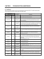
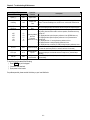
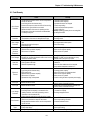
TROUBLESHOOTING & MAINTENANCE ............................................................................. 8-2
Fault Display......................................................................................................................................................8-2
Fault Remedy ....................................................................................................................................................8-2
Troubleshooting................................................................................................................................................8-2
How to Check Power Components..................................................................................................................8-2
Maintenance ......................................................................................................................................................8-2
Daily and Periodic Inspection Items................................................................................................................8-2
APPENDIX A - FUNCTIONS BASED ON USE ..................................................................................................... II
APPENDIX B - PARAMETERS BASED ON APPLICATION ................................................................................ II
APPENDIX C - PERIPHERAL DEVICES .............................................................................................................. II
DECLARATION OF CONFORMITY ...................................................................................................................... II
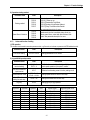
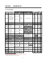
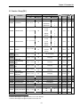
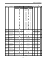
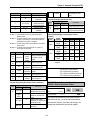
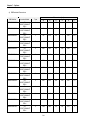
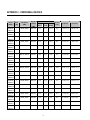
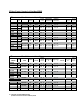
USER SELECTION GUIDE (ACtionMaster SPECIFICATIONS)
230V Class (1 ~ 30HP)
Model Number
SV xxx ACtionMaster - 2
008
015
022
037
055
075
110
150
185
220
2
3
5
7.5
10
15
20
25
30
Motor
HP
1
Rating1
kW
0.75
1.5
2.2
3.7
5.5
7.5
11
15
18.5
22
Capacity2 [kVA]
1.9
3.0
4.5
6.1
9.1
12.2
17.5
22.9
28.2
33.5
5
8
12
16
24
32
46
60
74
88
Output
FLA [A]
Ratings
Frequency
0 ~ 400 Hz (0-120Hz for Vector control)
Voltage
200 ~ 230 V 3
Input
Voltage
3 Phase, 200 ~ 230 V (± 10 %)
Ratings
Frequency
50 ~ 60 Hz (±5 %)
Braking Circuit
Dynamic
Braking4
On the Board
100%
100%
150%
150%
5 seconds
5 seconds
15 seconds
Controlled by Braking Unit 5
3 % ED
2 % ED
5 % ED
5 % ED
Average Braking
Torque
Max. Continuous
Baking Time
Max. Duty
Weight [lbs]
On the Board
On the Board
(Optional Resistor)
10.1
10.1
10.6
10.8
16.5
008
015
022
037
055
17.0
Optional (Braking Unit, Resistor) 4
30.4
31.5
42.8
44.1
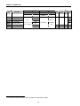
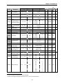
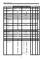
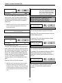
460V Class (1 ~ 30HP)
Model Number
SV xxx ACtionMaster - 4
150
185
220
HP
1
2
3
5
7.5
10
15
20
25
30
Rating1
kW
0.75
1.5
2.2
3.7
5.5
7.5
11
15
18.5
22
Capacity2 [kVA]
1.9
3.0
4.5
6.1
9.1
12.2
18.3
22.9
29.7
34.3
2.5
4
6
8
12
16
24
30
39
45
Output
FLA [A]
Ratings
Frequency
0 ~ 400 Hz (0-120Hz for Vector control)
Voltage
380 ~ 460 V 3
Input
Voltage
3 Phase, 380 ~ 460 V (± 10 %)
Ratings
Frequency
50 ~ 60 Hz (±5 %)
Dynamic
Braking Circuit
Max. Braking Torque
2
110
Motor
Braking4
1
075
On the Board
On the Board
100%
100%
On the Board
(Optional Resistor)
Optional (Braking Unit, Resistor) 4
150%
150%
Indicates the maximum applicable capacity when using a 4 Pole motor.
Rated capacity (√ 3*V*I) is based on 220V for 200V class and 440V for 400V class.
3
Maximum output voltage will not be greater than the input voltage. Output voltage less than the input voltage may be programmed.
4
1~5 HP inverters have internal braking resistors as standard. 7.5~10 HP inverters utilize optional braking resistors.
i
Max. Continuous
Baking Time
5 seconds
5 seconds
15 seconds
Controlled by Braking Unit 5
3 % ED
2 % ED
5 % ED
5 % ED
Max. Duty
Weight [lbs]
10.4
10.4
10.6
10.8
17.0
17.0
30.6
31.7
44.1
44.1
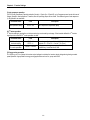
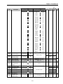
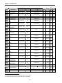
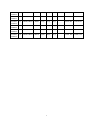
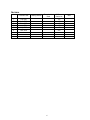
460V Class (40 ~ 100HP)
Model Number
SV xxx ACtionMaster - 4
300
370
450
550
750
40
50
60
75
100
Motor
HP
Rating1
kW
30
37
45
55
75
Capacity2 [kVA]
45
56
68
82
100
Output
FLA [A]
61
75
91
110
152
Ratings
Frequency
0 ~ 400 Hz (0-120Hz for Vector control)
Voltage
380 ~ 460 V 3
Input
Voltage
3 Phase, 380 ~ 460 V (± 10 %)
Ratings
Frequency
50 ~ 60 Hz (±5 %)
Braking Circuit
Optional (Braking Unit, Resistor) 4
Max. Braking Torque
150%
63
63
68
Dynamic
Braking4
Max. Continuous
Baking Time
Max. Duty
Controlled by Braking Unit 5
5 % ED
Weight [lbs]
45
45
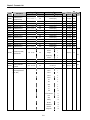
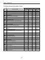
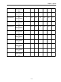
Common Features Specification
CONTROL
Control Method
Frequency Setting
Resolution
Frequency Accuracy
V/F Ratio
Overload Capacity
Input Signal
OPERATION
Torque Boost
Operation Method
Frequency Setting
Start Signal
Multi-Step
Multi Step
Accel/Decel Time
Emergency Stop
V/F Control,
Sensorless Vector Control (Speed/Torque), Sensored Vector Control (Speed/Torque) Selectable
Digital Reference: 0.01 Hz (Below 100 Hz), 0.1 Hz (Over 100 Hz)
Analog Reference: 0.03 Hz / 60 Hz
Digital: 0.01 % of Max. Output Frequency
Analog: 0.1 % of Max. Output Frequency
Linear, Square Pattern, User V/F
150 % of Rated Current for 1 Min., 200% of Rated Current for 0.5 sec. (Characteristic is Inversely
Proportional to Time)
Manual Torque Boost (0 ~ 20 %), Auto Torque Boost
Key / Terminal / Communication Operation
Analog: 0 ~ 10V / 4 ~ 20mA / Additional ports (VR: +12V, 10mA, V2: 0-10V) for Sub-Boards
Digital: Keypad
Forward, Reverse
Up to 8 Speeds can be Set (Use Multi-Function Terminal)
0 ~ 6,000 sec, Up to 4 Types can be Set and Selectable for Each Setting (Use Multi- Function
Terminal)
Accel/Decel Pattern: Linear, U-Curve, S-Curve Selectable
Instantly Interrupts the Inverter Output
5 Refer to Chapter 7 Options for DBU and DB Resistors
ii
Output Sig.
Jog
Auto Operation
Fault Reset
Operating Status
Fault Output
Indicator(FM,LM)
Operation Function
Protective Function
Inverter Trip
Inverter Alarm
Momentary Power Loss
Environment
Display
Operation
Information
Keypad
Trip
Information
Ambient Temperature
Storage Temperature
Ambient Humidity
Altitude - Vibration
Air Pressure
Application Site
Cooling Method
Jog Operation
Operates via Internal Sequence by Setting Multi-Function Terminal (5 Way * 8 Step)
Trip Status is Removed when Protection Function is Activated
Frequency Detection Level, Overload Alarm, Stalling, Over Voltage, Under Voltage, Inverter
Overheating, Running, Stop, Constant Speed, Inverter By-Pass, Speed Searching, Auto-Operation
Step, Auto-Operation Sequence
Contact Output (30A, 30C, 30B) – AC 250V 1A, DC 30V 1A
Choose 1 from Output Frequency, Output Current, Output Voltage, DC Voltage, Output Torque
Output Voltage: 0 ~ 10V (for FM: Linear output, 15V Max., LM), Pulse output: 500Hz (for LM).
DC Braking, Frequency Limit, Frequency Jump, Second Function, Slip Compensation, Reverse
Rotation Prevention, Auto Restart, Inverter By-Pass, Auto-Tuning, PID Control
Over Voltage, Under Voltage, Over Current, Fuse Open, Ground Fault, Inverter Overheating, Motor
Overheating, Output Phase Open,
Overload Protection, External Fault 1, 2, Communication Error, Loss of Speed Command, Hardware
Fault, Option Fault etc.
Stall Prevention, Overload Alarm, Temperature Sensor Fault
Less than 15msec: Continuous Operation,
More than 15msec: Auto Restart Possible
Output Frequency, Output Current, Output Voltage, Frequency Value Setting, Operating Speed, DC
Voltage, Output Torque
Indicates a Fault when the Protection Function activates, Retains Up to 5 Faults
-10 °C ~ 40 °C (14 °F ~ 104 °F), CE Certification: 41 °F ~ 104 °F (5 °C ~ 40 °C)
-20 °C ~ 65 °C (-4 °F ~ 149 °F)
Less Than 90 % RH Max. (Non-Condensing), CE Certification: 5 ~85% (Non-Condensing)
Below 1,000m or 3,300ft above sea level · Below 5.9m/sec2 (=0.6g)
86 ~ 106kPa
No Corrosive Gas, Combustible Gas, Oil Mist, or Dust
Forced Air Cooling
iii
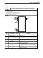
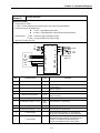
CHAPTER 1 -
INSTALLATION
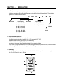
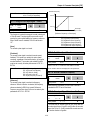
1.1 Inspection
Inspect the inverter for any damage that may have occurred during shipping.
Check the nameplate on the inverter. Verify the inverter unit is the correct one for the application. The numbering
system for the inverter is as shown below.
SV
CMC Inverter
Motor Capacity
008: 1 HP 185: 25 HP
015: 2 HP 220: 30 HP
022: 3 HP 300: 40 HP
037: 5 HP 370: 50 HP
055: 7.5 HP 450: 60 HP
075: 10 HP 550: 75 HP
110: 15 HP 750: 100 HP
150: 20 HP
008
Series Name
AC
2
N
Input Voltage
2 : 200 ~ 230V (±
±10%) 50/60Hz
4 : 380 ~ 460V (±
±10%) 50/60Hz
U
UL Listed
(UL508C)
Without
Keypad
1.2 Environmental Conditions
Verify ambient condition for the mounting location.
- Ambient temperature should not be below 14ºF (-10ºC) or exceed 104ºF (40ºC).
- Relative humidity should be less than 90% (non-condensing).
- Altitude should be below 3,300ft (1,000m).
Do not mount the inverter in direct sunlight and isolate it from excessive vibration.
If the inverter is going to be installed in an environment with high probability of penetration of dust, it must be located
inside watertight electrical boxes, in order to get the suitable IP degree.
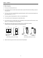
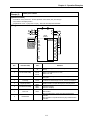
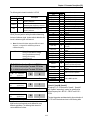
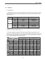
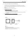
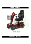
1.3 Mounting
The inverter must be mounted vertically with sufficient horizontal and vertical space between adjacent equipment
(A= Over 6" (150mm), B= Over 2" (50mm)).
A
B
B
A
1-1
Chapter 1 - Installation
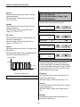
1.4 Other Precautions
Do not carry the inverter by the front cover.
Do not install the inverter in a location where excessive vibration is present. Be cautious when installing on presses or
moving equipment.
The life span of the inverter is greatly affected by the ambient temperature. Install in a location where temperature are
within permissible limits (- 10 ~ 40 ℃).
The inverter operates at high-temperatures - install on a non-combustible surface.
Do not install the inverter in high-temperature or high-humidity locations.
Do not install the inverter in a location where oil mist, combustible gas, or dust is present. Install the inverter in a clean
location or in an enclosed panel, free of foreign substance.
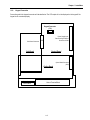
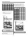
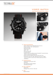
When installing the inverter inside a panel with multiple inverters or a ventilation fan, use caution.
If installed incorrectly, the ambient temperature may exceed specified limits.
Panel
Panel
Ventilating fan
Inverter
Inverter
Inverter
Inverter
Cooling fan
GOOD (O)
BAD (X)
GOOD (O)
[When installing several inverters in a panel]
BAD (X)
[When installing a ventilating fan in a panel]
Install the inverter using screws or bolts to insure the inverter is firmly fastened.
1-2
Chapter 1 - Installation
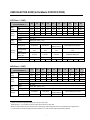
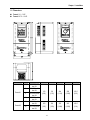
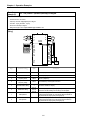
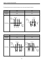
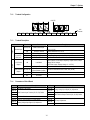
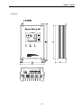
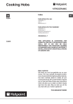
1.5 Dimensions
Frame # 1: 1 ~ 5 HP
Frame # 2: 7.5 ~ 10 HP
Frame
HP
1
2
Frame # 1
3
5
7.5
Frame # 2
10
Model Number
SV008ACtionMa
ster-2/4
SV015ACtionMa
ster-2/4
SV022ACtionMa
ster-2/4
SV037ACtionMa
ster-2/4
SV055ACtionMa
ster-2/4
SV075ACtionMa
ster-2/4
W1
W2
H1
H2
D1
150
(5.91)
130
(5.12)
284
(11.18)
269
(10.69)
156.5
(6.16)
200
(7.87)
180
(7.09)
355
(13.98)
340
(13.39)
182.5
(7.19)
1-3
Chapter 1 - Installation
BLANK
1-4
Chapter 1 - Installation
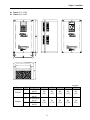
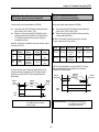
Frame # 3: 15 ~ 20 HP
Frame # 4: 25 ~ 30 HP
mm (inches)
Frame
Frame # 3
HP
15
20
25
Frame # 4
30
Model Number
SV110ACtionMa
ster-2/4
SV150ACtionMa
ster-2/4
SV185ACtionMa
ster-2/4
SV220ACtionMa
ster-2/4
W1
W2
H1
H2
D1
250
(9.84)
230
(9.06)
385
(15.16)
370
(14.57)
201
(7.91)
304
(11.97)
284
(11.18)
460
(18.11)
445
(17.52)
234
(9.21)
1-5
Chapter 1 - Installation
BLANK
1-6
Chapter 1 - Installation
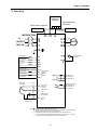
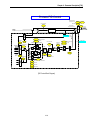
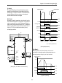
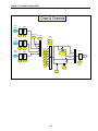
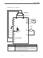
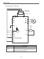
1.6 Basic Wiring
Dynamic
Braking Unit
(Optional)
4
DB Unit(Optional)
DB Resitor
3
DC Bus Choke (Optional)
P
N B1 B2
DC Bus Choke
DB Resistor
MCCB(OPTION)
P11 P21 N1
R
S
T
3φ
230/460 V
50/60 Hz
U
V
W
MOTOR
G( )
FM
Forward Run/Stop
FX
Reverse Run/Stop
RX
Inverter Disable
+
FM
Output Frequency Meter
(0~10V Linear)
5G
BX
Fault Reset
RST
Jog
JOG
Multi-function Input 1
P1
Multi-function Input 2
P2
Multi-function Input 3
P3
Common Terminal
Factory Setting:
‘Speed-L’
‘Speed-M’
‘Speed-H’
(N.O.) A
C
CM
Fault output relay
lless than AC250V, 1A
lless than DC30V, 1A
(N.C.) B
Potentiometer
(1 kohm, 1/2W)
Shield
Power supply for
AXA
+ 11V, 10mA
AXB
VR speed signal:
Multi-function output relay1
lless than AC250V, 1A
lless than DC30V, 1A
Factory setting: ‘Run’
V1 Speed signal input:
0 ~ 10V
I
Speed signal input:
4 ~20mA (250ohm)
5G Common for
Speed signal
VR, V1, I
Input2
Note)
1.
2.
3.
4.
Main Circuit Terminals
Control Circuit Terminals.
The terminal configuration varies depend on the model number. Please refer to the ‘1.7 Power terminals’.
Analog speed command may be set by Voltage, Current or both.
When installing the DC Reactor, the Common Busbar between P1 and P2 must be removed.
1 ~ 10 HP inverters have on-board braking circuit. Braking resistors are only included for 1 ~ 5 inverters.
15 ~ 30 HP inverters need optional braking unit and resistor for dynamic braking.
1-7
Chapter 1 - Installation
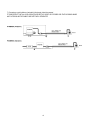
1.7 Power Terminals
Type A Configuration: 1 ~ 5 HP (SV008ACtionMaster-2, SV015ACtionMaster-2, SV022ACtionMaster-2,
SV037ACtionMaster-2, SV008ACtionMaster-4, SV015ACtionMaster-4, SV022ACtionMaster-4, SV037ACtionMaster-4)
R
S
T
G
N
B1
B2
U
V
W
Type B Configuration: 7.5 ~ 10 HP (SV055ACtionMaster-2, SV075ACtionMaster-2, SV055ACtionMaster-4,
SV075ACtionMaster-4)
R
S
T
G
P
N
B1
B2
U
V
W
Type C Configuration: 15 ~ 30 HP (SV110ACtionMaster-2, SV150ACtionMaster-2, SV185ACtionMaster-2,
SV220ACtionMaster-2, SV110ACtionMaster-4, SV150ACtionMaster-4, SV185ACtionMaster-4, SV220ACtionMaster-4)
R
S
Symbols
R
S
T
G
P
T
G
P1
P2
N
U
V
W
Functions
AC Line Voltage Input
(3 Phase, 200 ~ 230VAC or 380 ~ 460VAC)
Earth Ground
Positive DC Bus Terminal
DB Unit (P-P5) Connection Terminals
(DB Unit may be added when more braking duty (More than 30%ED) is required)
P1
P2
External DC Reactor (P1-P2) and DB Unit (P2-P6) Connection Terminals
N
Negative DC Bus Terminal
DB Unit (N-N7) Connection Terminal
B1
B2
U
V
W
Dynamic Braking Resistor (B1-B2) Terminals
3 Phase Power Output Terminals to Motor
(3 Phase, 200 ~ 230VAC or 380 ~ 460VAC)
“Suitable for use on a circuit capable of delivering not more than 10,000 rms symmetrical amperes,
240 volts maximum for 230V class models and 480 volts maximum for 460V class models.”
6 This P terminal is provided on optional Dynamic Braking Unit.
7
This N terminal is provided on optional Dynamic Braking Unit.
1-8
Chapter 1 - Installation
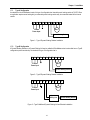
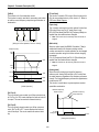
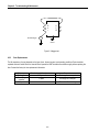
1.7.1 Type A Configuration
As standard on the ACtionMaster inverter, this type of configuration has internal dynamic braking resistor of 3% ED. When
an application requires more braking duty, an external dynamic braking resistor may be connected instead of the internal
resistor.
R
S
T
G
N B1 B2 U
3 Phase
Power Input
V
W
Motor
Dynamic Braking Resistor
Figure 1 – Type A Dynamic Braking Resistor Installation
1.7.2 Type B Configuration
A Dynamic Braking Resistor or a Dynamic Braking Unit may be added to ACtionMaster series inverters that have a Type B
configuration power terminal strip. As standard, this type of configuration has in
R
S
T
G
P
N B1 B2 U
3 Phase
Power Input
V
W
Motor
Dynamic Braking Resistor
Figure 2 – Type B Dynamic Braking Resistor Installation
R
S
T
G
P
N B1 B2 U
3 Phase
Power Input
V
W
Motor
Dynamic
Braking Unit
Dynamic Braking Resistor
Figure 3 – Type B Additional Dynamic Braking Unit and Resistor Installation
1-9
Chapter 1 - Installation
1.7.3 Type C Configuration
A Dynamic Braking Unit or a DC Bus Choke or both of them may be added to ACtionMaster series inverters that have a
Type A Configuration power terminal strip.
Jumper Between P1 and P2 Must Be Removed in Order
to Install a DC Bus Choke.
R
S
T
G P1 P2
N
U
3 Phase
Power Input
V
W
Motor
Dynamic
Braking
Unit
Dynamic Braking Resistor
DC Bus Choke
Figure 4 – Type C Dynamic Braking Unit, DC Bus Choke Installation
WARNING
Normal stray capacitance between the inverter chassis and the power devices inside the inverter and AC line
can provide a high impedance shock hazard. Refrain from applying power to the inverter if the inverter frame
(Power terminal G) is not grounded.
1-10
Chapter 1 - Installation
1.7.4
Wiring Power Terminals
Wiring Precautions
The internal circuits of the inverter will be damaged if the incoming power is connected and applied to output terminals
(U, V, W).
Use ring terminals with insulated caps when wiring the input power and motor wiring.
Do not leave wire fragments inside the inverter. Wire fragments can cause faults, breakdowns, and malfunctions.
For input and output, use wires with sufficient size to ensure voltage drop of less than 2%.
Motor torque may drop of operating at low frequencies and a long wire run between inverter and motor.
When more than one motor is connected to one inverter, total wire length should be less than 500m (1,640ft). Do not
use a 3-wire cable for long distances. Due to increased leakage capacitance between wires, over-current protective
feature may operate or equipment connected to the output side may malfunction.
Connect only recommended braking resistor between the B1 and B2 terminals. Never short B1 and B2 terminals.
Shorting terminals may cause internal damage to inverter.
The main circuit of the inverter contains high frequency noise, and can hinder communication equipment near the
inverter. To reduce noise, install line noise filters on the input side of the inverter.
Do not use power factor capacitor, surge killers, or RFI filters on the output side of the inverter. Doing so may damage
these components.
Always check whether the LCD and the charge lamp for the power terminal are OFF before wiring terminals. The
charge capacitor may hold high-voltage even after the power is disconnected. Use caution to prevent the possibility of
personal injury.
Grounding
The inverter is a high switching device, and leakage current may flow. Ground the inverter to avoid electrical shock.
Use caution to prevent the possibility of personal injury.
Connect only to the dedicated ground terminal of the inverter. Do not use the case or the chassis screw for grounding.
The protective earth conductor must be the first one in being connected and the last one in being disconnected.
As a minimum, grounding wire should meet the specifications listed below. Grounding wire should be as short as
possible and should be connected to the ground point as near as possible to the inverter.
Inverter Capacity
Below 5 HP
7.5 ~ 10 HP
15 ~ 20 HP
25 ~ 30 HP
Grounding wire Sizes, AWG (mm²)
200V Class
400VClass
12 ((3.5)
10 (5.5)
6 (14)
4 (22)
14 (2)
12 (3.5)
8 (8)
6 (14)
1-11
Chapter 1 - Installation
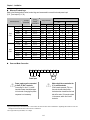
Wires and Terminal Lugs
Refer to the following table for wires, terminal lugs, and screws used to connect the inverter power input
(R, S, T) and output (U, V, W).
Inverter Capacity
200V
Class
400V
Class
1 ~ 3 HP
5 HP
7.5 HP
10 HP
15 HP
20 HP
25 HP
30 HP
1 ~ 5 HP
7.5 HP
10 HP
15 HP
20 HP
25 HP
30 HP
Screw
Torque8
(Kgf·cm)/lb-in
Terminal
Screw Size
M3.5
M3.5
M4
M4
M5
M5
M6
M6
M3.5
M4
M4
M5
M5
M6
M6
Wire9
Ring Terminals
AWG
mm²
R,S,T
U,V,W
R,S,T
U,V,W
R,S,T
U,V,W
2-4
2-4
5.5-5
14-5
14-5
22-6
38-8
38-8
2-4
5.5-5
14-5
14-5
22-6
38-8
38-8
2-4
2-4
5.5-5
8-5
14-5
22-6
38-8
38-8
2-4
5.5-5
8-5
14-5
22-6
38-8
38-8
2
3.5
5.5
14
14
22
30
38
2
3.5
3.5
5.5
14
14
22
2
3.5
5.5
8
14
22
30
30
2
2
3.5
5.5
8
8
14
14
12
10
6
6
4
2
2
14
12
12
10
6
6
4
14
12
10
8
6
4
2
2
14
14
12
10
8
8
6
15 / 10
15 / 10
15 / 10
15 / 10
26 / 18
26 / 18
45 / 31
45 / 31
15 / 10
15 / 10
15 / 10
26 / 18
26 / 18
45 / 31
45 / 31
Power and Motor Connection
R
S
T
G
N B1 B2 U
3 Phase
Power Input
V
W
Motor
Motor should be connected to the
U, V, and W terminals.
If the forward command (FX) is on,
the motor should rotate counter
clockwise when viewed from the load
side of the motor. If the motor rotates
in the reverse, switch the U and V
terminals.
Power supply must be connected
to the R, S, and T terminals.
Connecting it to the U, V, and W
terminals causes internal damages
to the inverter. Arranging the phase
sequence is not necessary.
8 Apply the rated torque to terminal screws. Loose screws can cause of short circuit or malfunction. Tightening the screws too much can
damage the terminals and cause a short circuit or malfunction.
9
Use copper wires only with 600V, 75℃ ratings.
1-12
Chapter 1 - Installation
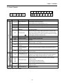
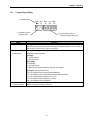
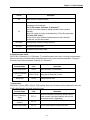
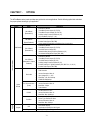
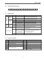
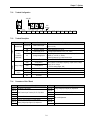
1.8 Control Terminals
P1
30A
Type
30C
30B
Symbol
Starting Contact Function Select
FX
RX
JOG
BX
RST
CM
NC
Analog frequency setting
Input signal
P1, P2, P3
VR
V1
I
Contact
Output signal
Analog
5G
FM
30A
30C
30B
AXA, AXC
Comm.
AXA AXC
CN3
P2
JOG CM
P3
CM
Name
FX
RX
NC
BX RST
VR
I
FM
V1
5G
Description
Multi-Function Input
1, 2, 3
Forward Run Command
Reverse Run Command
Jog Frequency
Reference
Used for Multi-Function Input Terminal.
(Factory default is set to “Step Frequency 1, 2, 3”.)
Forward Run When Closed and Stopped When Open.
Reverse Run When Closed and Stopped When Open.
Runs at Jog Frequency when the Jog Signal is ON. The Direction is set by
the FX (or RX) Signal.
When the BX Signal is ON the Output of the Inverter is Turned Off. When
Motor uses an Electrical Brake to Stop, BX is used to Turn Off the Output
Emergency Stop
Signal. When BX Signal is OFF (Not Turned Off by Latching) and FX Signal
!
(or RX Signal) is ON, Motor continues to Run.
Fault Reset
Used for Fault Reset.
Sequence Common
Common Terminal for Contact Inputs.
Not Used.
Frequency Setting Power Used as Power for Analog Frequency Setting.
(+12V)
Maximum Output is +12V, 100mA.
Used for 0-10V Input Frequency Reference. Input Resistance is 20 KΩ
Frequency Reference
(Voltage)
Used for 4-20mA Input Frequency Reference. Input Resistance is 250 Ω
Frequency Reference
(Current)
Frequency Setting
Common Terminal for Analog Frequency Reference Signal and FM
Common Terminal
(Frequency Meter).
Outputs One of the Following: Output Frequency, Output Current, Output
Analog Output (0~10V)
Voltage, DC Link Voltage and Torque. Default is set to Output Frequency.
(For External Monitoring)
Maximum Output Voltage and Output Current are 0-12V and 1mA.
Activates when Protective Function is Operating. AC250V, 1A or less;
DC30V, 1A or less.
Fault Contact Output
Fault: 30A-30C Closed (30B-30C Open)
Normal: 30B-30C Closed (30A-30C Open)
Multi-Function Output
Use After Defining Multi-Function Output Terminal. AC250V, 1A or less;
Relay
DC30V, 1A or less.
Communication Port
Keypad Connection Port.
Tightening Torque: 5.2 lb-in maximum.
1-13
Chapter 1 - Installation
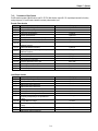
1.8.1
Wiring Control Terminals
Wiring Precautions
CM and 5G terminals are insulated to each other. Do not connect these terminals with each other and do not connect
these terminals to the power ground.
Use shielded wires or twisted wires for control circuit wiring, and separate these wires from the main power circuits
and other high voltage circuits.
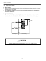
Control Circuit Terminal
The control input terminal of the control circuit is ON when the circuit is configured to the current flows out of the
terminal, as shown in the following illustration. CM terminal is the common terminal for the contact input signals.
Resistor
24 VDC
Current
FX
Resistor
RX
CM
External Sequence
Inverter Circuitry
CAUTION
Do not apply voltage to any control input terminals (FX, RX, P1, P2, P3, JOG, BX, RST, CM).
1-14
Chapter 1 - Installation
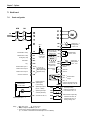
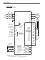
1.8.2
Keypad Connection
Connect keypad to the keypad connector as illustrated below. The LCD output will not be displayed on the keypad if the
keypad is not connected properly.
Keypad Connector
(CN3)
Sub-Board Connector
Power Supply Input,
Gate Drive Signal Output
Connector Socket
CN5
Sub-Board
Control Board
Option Board
Relay Output
Terminal Block
Option Board Connector
(CN2)
Control Terminal Block
1-15
Chapter 1 - Installation
Notes:
1-16
CHAPTER 2 -
OPERATION
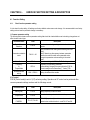
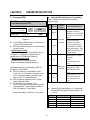
The ACtionMaster series inverter has seven parameter groups separated according to their applications as indicated in the
following table.
The ACtionMaster series inverter provides two kinds of keypad. One is of 32-character alphanumeric LCD keypad and the
other is of 7-Segment LED keypad.
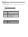
2.1 Parameter Groups
Parameter
Group
LCD Keypad
(Upper left Corner)
7-segment Keypad
(LED is lit)
Drive Group
DRV
‘DRV’ LED
Function 1 Group
FU1
‘FU1’ LED
Function 2 Group
FU2
‘FU2’ LED
Input / Output
Group
I/O
‘I/O’ LED
Sub-Board Group
EXT
‘EXT’ LED
Option Group
COM
‘I/O’ + ‘EXT’ LED
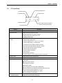
Description
Command Frequency, Accel/Decel Time etc.
Basic Parameters
Max. Frequency, Amount of Torque Boost etc.
Basic Related Parameters
Frequency Jumps, Max./Min. Frequency Limit etc.
Basic Application Related Parameters
Multi-Function Terminal Setting, Auto Operation etc.
Parameters needed for Sequence Operation
Displayed when Sub-Board is Installed.
Displayed when Option Board is Installed.
‘FU2’ + ‘I/O’ + ‘EXT’ Traverse, MMC (Multi-Motor Control), Draw etc.
LED
Application Related Parameters
Refer to the function descriptions in Chapter 6 for detailed description of each group.
Application Group
APP
2-1
Chapter 2 - Operation
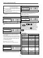
2.2 LCD Keypad
LCD keypad can display up to 32 alphanumeric characters, and various settings can be checked directly from the display.
The following is an illustration of the keypad.
The Program Button is
used to go into
programming mode to
change data.
32 character, back light,
LCD display. The back
light is adjustable.
The Enter Button is
used to enter changed
data within a parameter.
The Mode Button moves
you through the seven
program groups: DRV,
FUN1, FUN2, I/O, (EXT),
COM, and APP
[SHIFT] This button is
used to move cursor
across display in
programming mode.
[ESC] This button is used
to move the program
code to DRV 00 form any
program code.
The Up and Down
Arrows are used to
move through and
change data.
Forward Run Button.
The Forward Run LED
blinks when the drive
Accels or Decels.
Reverse Run Button.
The Reverse Run LED
blinks when the drive
Accels or Decels.
Stop Button is used to
stop the drive from
running.
The Reset Button is
used to reset Faults.
The LED blinks when
there is a fault.
2-2
Chapter 2 - Operation
2.2.1
LCD Keypad Display
3) Frequency Setting Source
2) Run/Stop Source
1) Parameter group
4) Output Current
DRV¢ºT/K
00 STP
0.0 A
0.00 Hz
5) Parameter Code
7) Drive Output Frequency During Run,
Command Frequency During Stop
6) Operating Status
Displays
1) Parameter Group
2) Run/Stop Source
3) Frequency Setting
Source
4) Output Current
5) Parameter Code
6) Operating Status
7) Drive Output Frequency
Command Frequency
Description
Displays the parameter group. There are DRV, FU1, FU2, I/O, EXT, COM, APP groups.
Displays the source of motor Run and Stop
K: Run/Stop using FWD, REV buttons on keypad
T: Run/Stop using control terminal input FX, RX
O: Run/Stop via option board
Displays the source of command frequency setting
K: Frequency setting using keypad
V: Frequency setting using V1 (0 ~10V) or V1 + I terminal
I: Frequency setting using I (4 ~ 20mA) terminal
U: Up terminal input when Up/Down operation is selected
D: Down terminal input when Up/Down operation is selected
S: Stop status when Up/Down operation is selected
O: Frequency setting via Option board
X: Frequency setting via Sub board
J: Jog terminal input
1 ~ 8: Step frequency operation
* During Auto operation, 2) and 3) display the ‘sequence number/step’.
Displays the Output Current during operation.
Displays the code of a group. Use the ▲(Up), ▼(Down) key to move through 0~99 codes.
Displays the operation information.
STP: Stop Status
FWD: During Forward operation
REV: During Reverse operation
DCB: During DC Braking
LOP: Loss of Reference from Option Board (DPRAM fault)
LOR: Loss of Reference from Option Board (Communication network fault)
LOV: Loss of Analog Frequency Reference (V1: 0~10V)
LOI: Loss of Analog Frequency Reference (I: 4~20mA)
LOS: Loss of Reference from Sub-Board
Displays the Output Frequency during run.
Displays the Command Frequency during stop.
2-3
Chapter 2 - Operation
2.2.2
Procedure for Setting Data (LCD Keypad)
1.
Press [MODE] key until the desired parameter group is displayed.
2.
Press [▲] or [▼] keys to move to the desired parameter code. If you know the desired parameter code, you can set
the code number of each parameter group in “Jump code”, except DRV group.
3.
Press [PROG] key to go into the programming mode, the cursor starts blinking.
4.
Press [SHIFT/ESC] key to move the cursor to the desired digit.
5.
Press [▲] or [▼] keys to change the data.
6.
Press [ENT] key to enter the data. The cursor stops blinking.
Note: Data cannot be changed when:
1) The parameter is not adjustable during the inverter is running. (Refer to the function table in Chapter 5), or,
2) Parameter Lock function is activated in FU2-94 [Parameter Lock].
2-4
Chapter 2 - Operation
2.2.3
Parameter Navigation (LCD Keypad)
The parameter group moves directly to DRV group by pressing [SHIFT/ESC] key in any parameter code.
Drive Group
FU1 Group
FU2 Group
I/O Group
MODE
DRV▶ T/K 0.0 A
00 STP 0.00 Hz
MODE
FU1▶ Jump code
00
1
▶
▶
◀
▶
◀
▶
▶
◀
▶
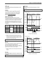
I/O▶ V1 volt x2
04
10.00 V
▶
◀
▶
◀
FU2▶ Last trip-5
05
-------
MODE
I/O▶ V1 freq y2
05
60.00 Hz
▶
◀
▶
◀
▶
◀
▶
◀
FU1▶ Stall Level
60
150 %
MODE
MODE
MODE
MODE
◀
▶
◀
MODE
MODE
FU1▶ DcSt value
08
50 %
MODE
I/O▶ V1 freq y1
03
0.00 Hz
FU2▶ Last trip-4
04
-------
▶
◀
▶
◀
DRV▶ Step freq-1
05
10.00 Hz
Fault
-------
◀
FU1▶ Stop mode
07
Decel
MODE
I/O▶ V1 volt x1
02
0.00 V
FU2▶ Last trip-3
03
-------
▶
◀
▶
◀
DRV▶ Freq mode
04
KeyPad-1
MODE
MODE
MODE
MODE
DRV▶
12
◀
▶
◀
▶
◀
FU1▶ Dec. pattern
06
Linear
DRV▶ Drive mode
03
Fx/Rx-1
I/O▶ V1 filter
01
10 ms
FU2▶ Last trip-2
02
-------
MODE
MODE
MODE
MODE
MODE
FU1▶ Acc. pattern
05
Linear
I/O▶ Jump code
00
1
MODE
FU2▶ Last trip-1
01
-------
▶
◀
▶
◀
MODE
MODE
▶
MODE
FU1▶ Run prohibit
03
None
DRV▶ Dec. time
02
20.0 sec
FU2▶ Jump code
00
30
◀
▶
◀
▶
◀
MODE
DRV▶ Acc. time
01
10.0 sec
MODE
MODE
MODE
FU2▶ Para. lock
94
0
2-5
I/O▶ Way1 / 2D
60
Forward
Chapter 2 - Operation
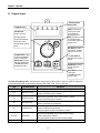
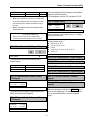
2.3 7-Segment Keypad
* Parameter Group
Display LEDs.
7-segment display
[SHIFT] This button is
used to move cursor
across display in
programming mode.
[ESC] This button is used
to move the program
code to DRV 00 from any
program code.
Encoder knob
Used to move you
through parameter
groups and parameter
code. Also, used to
change data by rotating
knob.
Run Button is used to
run the drive. The motor
direction is set in DRV
13.
The Run LED blinks
when the drive Accels or
Decels.
Program Button is used
to go into programming
mode to change data.
Enter Button is used to
enter the changed data.
The LED blinks during
programming mode.
Stop Button is used to
stop the drive from
running.
Reset Button is used to
reset Faults.
The LED blinks when
there is a fault.
* Parameter Group Display LEDs – When parameter code is located on DRV 20, DRV 21, DRV 22 and DRV 23, respectively,
by rotating the encoder knob, the parameter group display LEDs of DRV, FUN1, FUN2, I/O, EXT blink.
LED
Parameter Group
Description
DRV
Drive Group
FU1
FUNCTION 1 Group
FU2
FUNCTION 2 Group
I/O
Input/Output Group
EXT
Sub-Board Group
I/O + EXT
FU2 + I/O + EXT
Option Group
Application Group
Lit in Drive group.
Blinks when the parameter code is located on DRV 20 [FUN1].
Lit when FUNCTION 1 group is selected.
Blinks when the parameter code is located on DRV 21 [FUN2].
Lit when FUNCTION 2 group is selected.
Blinks when the parameter code is located on DRV 22 [I/O].
Lit when Input/Output group is selected
Blinks when the parameter code is located on DRV 23 [EXT].
Lit when Sub-Board group is selected.
This group appears only when a Sub-Board is installed.
Blinks when the parameter code is located on DRV 24 [EXT].
Lit when Option group is selected.
This group appears only when an Option Board is installed.
Blinks when the parameter code is located on DRV 25 [FUN2].
2-6
Chapter 2 - Operation
2.3.1
7-Segment Keypad Display
1) Parameter Group
DRV FU1
FU2
I / O EXT
2) Parameter Code and
Operating Status
3) Output Frequency during run,
Command Frequency during stop
Display
1) Parameter Group
2) Parameter Code and
Operating Status
3) Output Frequency,
Command Frequency
Description
Displays the parameter groups of DRV, FU1, FU2, I/O, EXT, COM, APP groups.
Each LED is lit when its parameter group is selected and blinks when the parameter code is located on
DRV 20, DRV 21, DRV 22, DRV 23, DRV 24, and DRV 25.
Displays the code of a group. Rotate the encoder knob to move through 0 ~ 99 codes.
Displays the operation information.
[First digit]
F: Forward operation
r: Reverse operation
[Second digit]
d: DC Braking
J: Jog Terminal Input
1~8: Step Frequency Input (Displays the Step of the Auto operation)
[Two digits] - when the reference is lost.
LP: Loss of Reference from the Option Board (DPRAM fault)
Lr: Loss of Reference from the Option Board (Communication network fault)
Lv: Loss of Analog Frequency Reference (V1: 0~10V)
LI: Loss of Analog Frequency Reference (I: 4~20mA)
LX: Loss of Reference from the Sub-Board
Displays the Output Frequency during run.
Displays the Command Frequency during stop.
2-7
Chapter 2 - Operation
2.3.2
Procedure for Setting Data (7-Segment Keypad)
In DRV Group:
1.
Rotate the encoder knob until the desired parameter code is displayed.
2.
Press [PROG/ENT] key to go into the programming mode, then the display blinks.
3.
Press [SHIFT/ESC] key to move the cursor to the desired digit.
4.
Rotate the encoder knob to change the data.
5.
Press [PROG/ENT] key to enter the changed data.
In FUN1 Group:
1.
Rotate the encoder knob until parameter code ‘20’ is displayed in drive group.
2.
Press [PROG/ENT] key to go into the FUN1 group.
3.
Rotate the encoder knob until the desired parameter code is displayed.
4.
Press [PROG/ENT] key to go into the programming mode, then the display blinks.
5.
Press [SHIFT/ESC] key to move the cursor to the desired digit.
6.
Rotate the encoder knob to change the data.
7.
Press [PROG/ENT] key to enter the changed data.
In FUN2 Group:
1.
Rotate the encoder knob until parameter code ‘21’ is displayed in drive group.
2.
Go to step 2 of ‘In FUN1 Group’ above, and follow the rest procedure.
In I/O Group:
1.
Rotate the encoder knob until parameter code ‘22’ is displayed in drive group.
2.
Go to step 2 of ‘In FUN1 Group’ above, and follow the rest procedure.
2-8
Chapter 2 - Operation
2.3.3
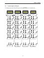
Parameter Navigation (7-Segment Keypad)
The parameter group moves directly to DRV group by pressing [SHIFT/ESC] key in any parameter code.
DRV Group
DRV FU1 FU2
I / O EXT
DRV FU1 FU2
I / O EXT
DRV FU1 FU2
I / O EXT
SHIFT
ESC
Encoder Knob
PROG
ENT
DRV FU1 FU2
I / O EXT
DRV FU1 FU2
I / O EXT
DRV FU1 FU2
I / O EXT
DRV FU1 FU2
I / O EXT
DRV FU1 FU2
I / O EXT
DRV FU1 FU2
I / O EXT
DRV FU1 FU2
I / O EXT
PROG
ENT
FU1 Group
DRV FU1 FU2
I / O EXT
PROG
ENT
FU2 Group
DRV FU1 FU2
I / O EXT
PROG
ENT
I/O Group
2-9
Chapter 2 - Operation
2.4 Operation Method
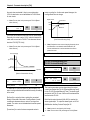
The ACtionMaster has several operation methods as shown below.
Operation Method
Operation using Keypad
Operation using
Control Terminals
Operation using both
Keypad and Control
Terminals
Operation using
Option Boards
Function
Run/Stop command and frequency are set only through the
keypad.
Closing FX or RX terminal performs Run/Stop.
Frequency reference is set through V1 or I or V1+I terminal.
Run/Stop is performed by the keypad.
Frequency reference is set through the V1 or I or V1+I
terminal.
Closing FX or RX terminal performs Run/Stop.
Frequency reference is set through the keypad.
Operation using option board.
The ACtionMaster has five option boards and three subboards.
Option Boards: RS485, Device-Net, F-Net, ProfiBus and
ModBus
Sub-Boards: Sub-A Board, Sub-B Board, Sub-C Board and
Sub-D Board.
2-10
Function Setting
DRV 03: Keypad
DRV 04: Keypad-1 or -2
DRV 03: Fx/Rx-1 or -2
DRV 04: V1 or I or V1+I
DRV 03: Keypad-1 or -2
DRV 04: V1 or I or V1+I
DRV 03: Fx/Rx-1 or -2
DRV 04: Keypad-1 or -2
Please refer to ‘Chapter 7 Options’ for more
information.
Chapter 2 - Operation
Notes:
2-11
CHAPTER 3 -
QUICK-START PROCEDURES
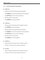
These Quick-Start Up instructions are for those applications where:
The user wants to get the ACtionMaster inverter started quickly
The factory-preset values are suitable for the user application
The factory-preset values are shown on the ‘Chapter 4 - Parameter List’. The ACtionMaster inverter is configured to
operate a motor at 60Hz (base frequency). If the application requires coordinated control with other controllers, it is
recommended the user become familiar with all parameters and features of the inverter before applying AC power.
1.
Mounting the inverter (mount the inverter as described in ‘1.3 Mounting’)
Install in a clean, dry location
Allow a sufficient clearance around top and sides of inverter
The ambient temperature should not exceed 40°C (104°F)
If two or more inverters are installed in an enclosure, add additional cooling
2.
Wiring the inverter (connect wiring as described in ‘1.7 Power Terminals’)
AC power should be turned OFF
Verify the AC power matches the nameplate voltage
Remove the screw on the bottom front cover of the inverter for terminal board access (For terminal board access
on 15~ 30HP inverters you must disconnect the keypad cable from the inverter and fully removed the cover)
3-1
Chapter 3 - Quick-Start Procedures
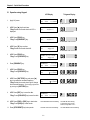
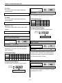
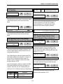
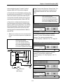
3.1 Operation using Keypad
LCD Display
1.
Apply AC power.
DRV►T/K
00 STP
7-Segment Display
0.0 A
0.00Hz
The DRV LED is ON.
2.
3.
LCD: Press [▲] key three times.
7-Seg: Rotate the encoder knob until ‘03’ is
displayed.
DRV► Drive mode
03
Fx/Rx-1
LCD: Press [PROG] key.
7-Seg: Press[PROG/ENT] key.
DRV► Drive mode
03
Fx/Rx-1
The DRV LED is turned ON.
The PROG/ENT LED turned ON.
4.
LCD: Press [▼] key one time.
7-Seg: Rotate the encoder knob left.
DRV► Drive mode
03
Keypad
The PROG/ENT LED is turned ON.
5.
LCD: Press [PROG] key.
7-Seg: Press [PROG/ENT] key.
DRV► Drive mode
03
Keypad
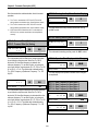
6.
Press [PROG/ENT] key.
DRV►K/K
00 STP
7.
LCD: Press [PROG] key.
7-Seg: Press [PROG/ENT] key.
0.0 A
0.00Hz
DRV► Cmd. freq
00
0.00Hz
The PROG/ENT LED is turned ON.
8.
9.
LCD: Press [SHIFT/ESC] key and press [▲]
key to increase the command frequency.
7-Seg: Rotate the encoder knob right to change
the command frequency. The changing digit moves
by pressing the [SHIFT/ESC] key.
LCD: Press [ENT] key to save the data.
7-Seg: Press [PROG/ENT] key to save the data.
DRV► Cmd. freq
00
60.00Hz
The PROG/ENT LED is turned ON.
DRV►K/K
00 STP
0.0 A
60.00Hz
10. LCD: Press [FWD] or [REV] key to start motor.
7-Seg: Press [RUN] key to start motor.
The STOP/RESET LED starts blinking.
The RUN LED starts blinking.
To change the motor running
direction, change DRV 13 to ‘1’.
11. Press [STOP/RESET] key to stop motor.
The FWD or REV LED starts blinking.
The STOP/RESET LED starts blinking.
3-2
Chapter 3 - Quick-Start Procedures
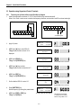
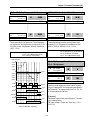
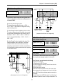
3.2 Operation using Control Terminals
LCD Display
1.
7-Segment Display
Install a potentiometer on terminals V1, VR, 5G
and connect wiring as shown below.
1 ㏀, 1/2 W
P1 P2 P3 FX RX NC VR VI
JOG CM CM BX RST
2.
I
FM 5G
Apply AC power.
DRV►T/K
00 STP
0.0 A
0.00Hz
The DRV LED is ON.
3.
Confirm that the DRV 03 is set at ‘Fx/Rx-1’.
DRV► Drive mode
03
Fx/Rx-1
4.
LCD: Press [▲] key to move DRV 04.
7-Seg: Rotate encoder knob until ‘04’ is
displayed.
DRV►
04
Freq mode
Keypad-1
5.
LCD: Press [PROG] key.
7-Seg: Press [PROG/ENT] key.
DRV►
04
Freq mode
Keypad-1
The PROG/ENT LED is turned ON.
6.
LCD: Press [▲] key and set at ‘V1’.
7-Seg: Rotate encoder knob and set at ‘2’.
DRV►
04
Freq mode
V1
The PROG/ENT LED is turned ON.
LCD: Press [ENT] key.
7-Seg: Press [PROG/ENT] key.
DRV►
04
8.
Press [SHIFT/ESC] key.
DRV►T/V
00 STP
0.0 A
0.00Hz
9.
Set the frequency by rotating the potentiometer.
DRV►T/V
00 STP
0.0 A
60.00Hz
7.
Freq mode
V1
The PROG/ENT LED is turned OFF.
10. Close the FX or RX contact to run the motor.
The FWD or REV LED starts blinking.
The RUN LED starts blinking.
11. Open the FX or RX contact to stop the motor.
The STOP/RESET LED starts blinking.
The STOP/RESET LED starts blinking.
3-3
Chapter 3 - Quick-Start Procedures
3.3 Operation using Keypad and Control Terminals
3.3.1 Frequency set by External Source and Run/Stop by Keypad
1. Install a potentiometer on terminals V1, VR, 5G and connect wiring as shown below left.
When a ‘4 to 20mA’ current source is used as the frequency reference, use terminals I and 5G as shown below right.
DRV 04 must be set at V1.
DRV 04 must be set at I.
1 ㏀, 1/2 W
P1 P2 P3 FX RX NC VR VI
JOG CM CM BX RST
I
FM 5G
P1 P2 P3 FX RX NC VR VI
JOG CM CM BX RST
I
FM 5G
4 to 20mA signal
2.
Apply AC power.
DRV►T/K
00 STP
0.0 A
0.00Hz
The DRV LED is ON.
3.
LCD: Press [▲] key to move DRV 03.
7-Seg: Rotate encoder knob until ‘03’ is
displayed.
DRV► Drive mode
03
Fx/Rx-1
4.
LCD: Press [PROG] key.
7-Seg: Press [PROG/ENT] key.
DRV► Drive mode
03
Fx/Rx-1
LCD: Press [▲] key one time.
7-Seg: Rotate encoder knob and set at ‘0’.
DRV► Drive mode
03
Keypad
5.
The PROG/ENT LED is turned ON.
The PROG/ENT LED is turned ON.
6.
7.
LCD: Press [ENT] key.
7-Seg: Press [PROG/ENT] key.
DRV► Drive mode
03
Keypad
Confirm that the DRV 04 is set at ‘V1’.
DRV►
04
The PROG/ENT LED is turned OFF.
Freq mode
V1
The PROG/ENT LED is turned ON.
8.
Press [SHIFT/ESC] key.
Set the frequency by rotating the potentiometer.
9.
LCD: Press [FWD] or [REV] key.
7-Seg: Press [RUN] key.
DRV►T/V
00 STP
0.0 A
60.00Hz
The FWD or REV LED starts blinking.
3-4
The RUN LED starts blinking.
To change the motor running
direction, change DRV 13 to ‘1’.
Chapter 3 - Quick-Start Procedures
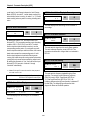
3.3.2
1.
Frequency set by Keypad and Run/Stop by External Source.
LCD Display
Connect wiring as shown below.
7-Segment Display
P1 P2 P3 FX RX NC VR VI
JOG CM CM BX RST
2.
I
FM 5G
Apply AC power.
DRV►T/K
00 STP
0.0 A
0.00Hz
The DRV LED is ON.
3.
Confirm that the DRV 03 is set at ‘Fx/Rx-1’.
DRV► Drive mode
03
Fx/Rx-1
4.
Confirm that the DRV 04 is set at
‘Keypad-1’.
DRV►
04
5.
Press [SHIFT/ESC] key.
DRV►T/K
00 STP
6.
LCD: Press [PROG] key.
7-Seg: Press [PROG/ENT] key.
DRV► Cmd. freq
00
0.00Hz
LCD: Set the frequency using [SHIFT/ESC] and
[▲] key.
7-Seg: Set the frequency by rotating the encoder
knob.
DRV► Cmd. freq
00
60.00Hz
8.
LCD: Press [ENT] key to save the data.
7-Seg: Press [PROG/ENT] key to save the data.
DRV►T/V
00 STP
9.
Close the FX or RX contact to run the motor.
The FWD or REV LED starts blinking.
7.
10. Open the FX or RX contact to stop the motor.
Freq mode
Keypad-1
0.0 A
0.00Hz
The PROG/ENT LED is turned ON.
The PROG/ENT LED is turned ON.
0.0 A
60.00Hz
The RUN LED starts blinking.
The STOP/RESET LED starts blinking. The STOP/RESET LED starts blinking.
3-5
CHAPTER 4 -
VARIOUS FUNCTION SETTING & DESCRIPTION
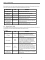
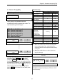
4.1 Function Setting
4.1.1
Basic function parameter setting
It is the basic function setting. All settings are factory defaults unless users make change. It is recommended to use factory
setting value unless the parameter change is necessary.
1) Common parameter setting
The following table shows common parameter setting that should be checked before use but making change does not
affect inverter control type.
Parameter Name
Code
Rated Motor
Selection
FU2-30
Parameters related to
motor
FU2-31 ~ 36
Drive Mode
Frequency
or
Torque Mode
Accel/Decel time
setting
DRV-3
DRV-4
DRV-1, DRV-2
Description
Select motor and voltage rating suitable to the desired
inverter
Basic parameter value setting when selecting the motor
rating.
Note) If there is any discrepancy between parameter
preset value and the actual motor parameter value,
change the parameter value according to the actual
motor.
Operation via Keypad, Fx/Rx-1, Fx/Rx-2 setting enable
Frequency/Torque setting parameter
It automatically changes to torque mode when FU2 39[Control mode] is set to Sensorless_T, Vector_TRQ
Setting Accel/Decel time enable
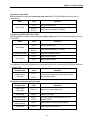
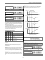
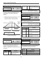
2) V/f control
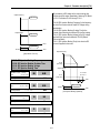
FU2-39 [Control mode] is set to 0 (V/F) as factory setting. Operation via V/F control can be performed after
common parameter settings are done and the followings are set.
Parameter Name
Code
Description
Starting freq.
FU1-22
Setting frequency to start the motor
Torque boost
FU1-26
Manual or Auto torque boost settable in this parameter
Torque boost value in
FWD/REV
FU1-27, FU1-28
If FU1-26 [torque boost] is set to manual, user sets the
desired value and the direction in code FU1-27 and 28.
Chapter 4 – Function Settings
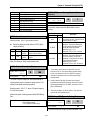
3) V/F + PG control
If FU2-39 [control mode] is set to V/F with PG (encoder) feedback using SUB-B or SUB-D boards, the control type is
automatically changed to V/F + PG. The following parameters should be set accordingly to enable PG feedback using SUBB or SUB-D boards.
Parameter Name
Usage of Pulse Input
Signal
Pulse Input Signal
Selection
Encoder Pulse
Number
P-Gain for ‘Sub-B’
I-Gain for ‘Sub-B’
Slip Frequency for
‘Sub-B’ Board
Code
Description
EXT-12
Defines the use of pulse input signal with SUB-B or SUBD mounted. This parameter should be set to 1 {Feedback}.
EXT-15
Three types of input signal settable;
(A+B), A, -(A+B)
EXT-16
Defines the number of encoders of the motor.
EXT-22, EXT-23
PI gains for PI controller during PG operation
EXT-24
Setting as a percent of FU2-32 [Rated Motor Slip]
4) Slip compensation
operation is done via Slip compensation if FU2-39 is set to 1 {Slip compen}. This control keeps motor speed constant
regardless of load change.
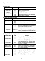
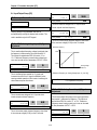
5) Auto-tuning of motor constant
This parameter enables auto-tuning of the motor constants. If set to 1 {All mode}, tuning type varies according to what
control mode is set in [FU2-39]. Auto-tuning can be done in two ways – one is motor non-rotation mode, the other is motor
rotation mode.
① Auto-tuning by non-rotation mode: Rs+Lsigma
② Auto-tuning by rotation mode : All, Enc Test, Tr
Before performing Auto-tuning, set motor rating, motor parameter in common setting and select the desired
control mode in FU2-39 [control mode selection]. However, when auto-tuning parameters related to encoder, detail
functions settings of vector control should be pre-defined. If Enc Test, Tr and control mode are set to vector control,
Sub-B or Sub-D board should be mounted.
Parameter Name
Code
Auto-tuning
FU2-40
Parameter value
display
FU2-34,
FU2-41 ~ 44
Description
No, All, Rs+Lsigma, Enc Test, Tr
Tuned value monitoring
(no-load current, stator/rotor resistance, leakage
inductance, rotor filter time constant)
4-2
Chapter 4 – Function Settings
FU2-40
Description
No
Motor constants calculation disabled
All
All constants can be measured in this code but different constants are tuned
according to control mode type;
For V/F, Slip compen , Sensorless_S, Sensorless_T:
(No-load current, stator resistance, leakage inductance, stator inductance
available)
Note) Only no-load current can be calculated during V/F and Slip compensation.
For Vector_SPD, Vector_T:
No-load current, stator resistance, leakage inductance, stator inductance,
encoder test, rotor filter time constant
Rs+Lsigma
Enc Test
Tr
Calculate stator resistance, leakage inductance
Calculate the encoder status
Calculate Rotor filter time constant
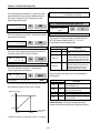
6) Sensorless vector control
Set FU2-39 to 2 {Sensorless_S} or 3 {Sensorless_T} to enable Sensorless vector control. It is strongly recommended to
perform Auto-tuning for Sensorless before starting Sensorless control in order to maximize performance. Two types of
Sensorless vector control are available; Sensorless_S or Sensorless_T.
Parameter Name
Code
Description
Control mode selection
FU2-39
Select Sensorless_S or Sensorless_T
P, I gain for sensorless
control
FU2-45, FU2-46
Setting gain for Sensorless_S control
Starting freq
FU1-22
Starting freq of the motor
7) Vector control
Set FU2-39 to 4 {Vector_SPD} or 5{Vector_TRQ} to enable Vector control. Encoder should be installed to the motor with
Sub-B or Sub-D boards in the inverter to start this control.
Parameter Name
Code
Usage of Pulse Input
Signal
EXT-12
Pulse Input Signal
Selection
EXT-15
Encoder Pulse Number
EXT-16
Description
Defines the method of pulse input with SUB-B or SUB-D
boards mounted. Vector control setting is valid only after
this parameter is set to 1 {Feed-back}.
3 types of pulse input : (A+B), A, -(A+B)
Enter the pulse number of encoder in the motor.
4-3
Chapter 4 – Function Settings
Before selecting Vector control mode, encoder setting should be done as indicated above. If the parameter value of actual
motor is set in common setting, execute Auto-tuning before selecting vector control mode.
Parameter Name
Code
Control Mode Selection
FU2-39
Forward/ Reverse
Torque Limit
P-Gain/ I-Gain for
(Sensored) Vector_SPD
EXT-27, EXT-28
Description
Select Vector_SPD or Vector_TRQ
Setting the FWD/REV limit to the torque current
EXT-25, EXT-26
Setting P/I Gain for Vector_SPD control
Speed Limit setting
EXT-50, EXT-51
EXT-52, EXT-53
Setting speed limit for Vector_TRQ
Zero Speed Detection
Level/ Bandwidth
EXT-54, EXT-55
Setting on/off of Multi-function output terminal relay when
the motor speed reaches to 0.
Torque Detection
Level/Bandwidth
EXT-56, EXT-57
Detect certain level/bandwidth of Torque
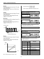
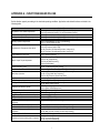
4.1.2 Advanced function 1 setting
SV-ACtionMaster inverter features advanced function parameters to maximize efficiency and performance of the motor. It is
recommended to use as factory setting unless parameter value change is necessary.
1) V/F control
Parameter Name
V/F Pattern
Code
Description
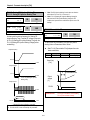
FU1-29
Use it according to load characteristics. If User V/F is
selected, User can select the optimum output V/F
characteristic for the aplication and load characteristics in
[FU1-30]~[FU1-37]
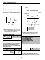
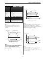
Dwell operation
FU2-07
FU2-08
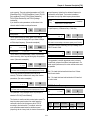
Frequency jump
FU2-10
FU2-11~16
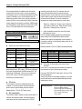
S-shaped curve
Accel/Decel pattern
FU2-17/ FU2-18
Used to output torque in an intended direction. Inverter
stops acceleration for the preset [FU2-08] Dwell time
while running at Dwell frequency [FU2-07] and starts
acceleration at commanded frequency. Setting [FU2-08]
Dwell time to 0 disable the Dwell operation.
When it is desired to avoid resonance attributable to the
natural frequency of a mechanical system, these
parameters allow resonant frequencis to be jumped. Up to
three areas can be set, with the jump frequencies set to
either the top or bottom point of each area. To enable the
function, set [FU2-10] to ‘Yes’ and set the value in [FU211]~[ FU2-16].
This pattern has an effect on the prevention of cargo
collapse on conveyor etc and reduction in an acceleration/
deceleration shock.
4-4
Chapter 4 – Function Settings
2) Sensorless vector control
Related parameters for starting during Sensorless vector control when FU2-39 [Control Mode Selection] is set to 2
{Sensorless_S}.
Status
Code
FU1-14
When starting
I/O12~14
EXT2~4
Description
Setting pre-excitation time
Multi-function input terminal P1- P6 define
3) Vector control [Vector_SPD, Vector_TRQ]
Related parameters for starting/ running/ stopping during Vector control when FU2-39 [Control Mode Selection] is set to 4
{Vector_SPD}.
Status
Code
FU1-14
Description
Setting pre-excitation time
When starting
I/O12~14
EXT2~4
Pre-excitation current
FU1-16
Setting the Pre-excitation current
FU1-15
Setting hold time at a stop
FU1-7
Stopping method selection
When stopping
Multi-function input terminal P1- P6 define
This parameter can limit the over-speeding (motor running above limit level) of the motor when FU2-39[Control mode] is set
to 5 {Vector_TRQ}.
Parameter Name
Code
Speed limit level
/ bias / gain
EXT-50
~
EXT-53
Description
Function to limit the speed and change reference torque
value according to speed
4) Parameters to view motor and inverter status
Parameter Name
Code
Description
Output current/
motor speed
DRV 8 ~ 9
DC link voltage
DRV 10
Display DC link voltage
User display selection
(Voltage and watt)
Reference/ Feedback
frequency display
DRV11
FU2-73
Either output voltage or power selected in FU2-73 is
displayed in DRV11.
DRV15
Display Reference/ Feedback frequency display
Fault display
DRV12
Display the current inverter fault
Display output current and motor rpm
4-5
Chapter 4 – Function Settings
5) Parameter initialize
Parameter Name
Code
Description
Software version
FU2-79
Display the inverter software version
Parameter
Read/Write/Initialize/Write
protection
FU2-91
FU2-92
FU2-93
FU2-94
[FU2-91], [FU2-92]: Copying parameters from other
inverter enabled
[FU2-93]: Initializing parameters to factory setting values
[FU2-94] : Parameter write disabled
6) Protection & fault detection level setting
Parameter Name
Electronic thermal
Overload alarm and trip
Stall prevention
Code
FU1-50
FU1-51
FU1-52
FU1-53
FU1-54, FU1-55
FU1-56, FU1-57
FU1-58
Description
Protection of the motor from overheating without the use of
external thermal relay. Refer to parameter descriptions for
more detail.
Warning alarm outputs and displays the trip message when
overcurrent above the threshold value keeps on.
Set the output current level at which the output freq will be
adjusted to prevent the motor from stoping due to overFU1-59, FU1-60
current etc. it activates during accel/ constant speed/ decel
to prevent the motor stall.
7) Starting / Accel/ Decel / Stopping pattern setting
Parameter Name
Code
Accel/Decel pattern
FU1-05
FU1-06
Stopping method
FU1-07
Starting DC Injection
Braking Voltage/ Time
FU1-12
FU1-13
Frequency Limit selection
FU1-23
Fu1-24
FU1-25
Dynamic braking
FU2-75
FU2-76
Description
5 types of Accel/ Decel pattern: ‘Linear’, ‘S-curve’, ’Ucurve’, ’Minimum’, ‘Optimum’ settable according to
appplication and load characteristic. If ‘S-curve’ is selected,
the desired value of [FU2-17], [FU2-18] is settable.
3 types of stopping method ‘Decel’, ‘DC-brake’, ‘Free-run’
selectable. If ‘DC-brake’ is selected, the desired value of
[FU1-8]~ [FU1-11] is settable.
The motor accelerates after the preset [FU1-12] for the
preset [FU1-13] is applied. Starting DC injection braking is
inactive when the value is set to 0 in control mode other
than V/F and Slip compensation.
Limits the active frequency. Inverter operates at the freq
range between upper freq limit [FU1-25] and bottom freq
limit [FU1-24] and higher/ lower freq value is entered, it is
automatically replaced by limit value. Setting range: [FU120] Maximum freq to [FU1-21] Base freq.
Select the DB resistor mode when the regenerative load. Is
connected. Refer to DBU manual for more details.
4-6
Chapter 4 – Function Settings
8) Operation-starting method
Parameter Name
Code
Description
Starting method
FU2-20
FU2-21
FU2-26
FU2-27
Motor starting method:
[FU2-20] : Power-on run,
[FU2-21] Restart after Fault Reset,
[FU2-26] Number of Auto Restart Attempt
[FU2-27] Delay Time Before Auto Restart
See parameter description for more.
Speed Search Selection
FU2-22
FU2-23
FU2-24
FU2-25
Speed search function is available during Accel, trip,
instant power failure, restart after fault reset and auto
restart. See parameter description for more.
4.1.3 Advanced function 2 setting
1) PID operation
The inverter can be used to exercise process control, e.g. flow rate, air volume or pressure via PID feedback control.
Parameter Name
Code
PID control setting
FU2-41~ FU2-60
Description
Setting parameters for PID control
2) Jog and Multi-speed operation
Parameter Name
Code
Multi function input
terminal setting
Filter time constant for
input terminal
I/O-12 ~14
EXT2 ~ 4
If I/O-12 ~14 are set to Speed-H, Speed-M, Speed-L,
multi- speed operation up to speed 7 enable..
I/O-17
Effective for eliminating noise in the freq. setting circuit
Speed reference value
DRV-05 ~ 7
I/O-21 ~ I/O-24
Accel/Decel time
setting for each step
I/O-25 ~ 38
Jog freq.
I/O-20
Description
Setting speed reference value for each step
Setting Accel/Decel time for each step
Setting jog freq for jog operation
Speed-H
Speed-M
Speed-L
JOG
Speed Signal
Applied speed value
0
X
0
0
0
1
1
1
1
0
x
0
1
1
0
0
1
1
0
X
1
0
1
0
1
0
1
0
1
0
0
0
0
0
0
0
Speed 0
Jog freq.
Speed –1
Speed –2
Speed –3
Speed –4
Speed –5
Speed –6
Speed –7
DRV-00
I/O-20
DRV-05
DRV-06
DRV-07
I/O-21
I/O-22
I/O-23
I/O-24
4-7
Chapter 4 – Function Settings
3) Auto sequence operation
If I/O-50 [Auto (Sequence) Operation selection] is set to 1 {Auto-A} or 2 {Auto-B}, up to 5 sequences can be set with max of
8 steps (speed) in each sequence. Therefore, max 40 operating steps can be made. Two different types of auto sequence
(A, B) operation are available.
Parameter Name
Code
Auto operation setting
I/O-50 ~ 84
Description
Set 8 steps and 5 sequences (Max)
4) 2nd motor operation
2nd function setting is required to run the two motors by one inverter by exchange. If the terminal defined for 2nd function
signal input is turned ON, 2nd motor operation is valid.
Parameter Name
Code
Description
Multi-function input
terminals setting
Parameter setting for
2nd motor operation
I/O-12 ~14
EXT2 ~ 4
2nd motor operation is available with Multi-function input
terminals P1 ~ P3 or P4 ~ 6 set to 7 {2nd Func}.
Setting parameters necessary to operate 2nd motor such
as base freq., Accel/Decl time, Stall.
FU2-81 ~ FU2-90
5) Energy-saving operation
FU1-39 [Energy Save Level] tunes the inverter output voltage to minimize the inverter output voltage during during constant
speed operation. Appropriate for energy-saving applications such as fan, pump and HVAC.
4-8
Chapter 4 – Operation Examples
4.2 Operation Example
Operation
Example (1)
V/F Control + Analog Voltage Input (V1) + Operation via Terminal (FX/RX)
[Operation condition]
-. Control mode : V/F control
-. Frequency command : 50[Hz] analog input via V1 terminal
-. Accel/Decel time : Accel – 15 [Sec], Decel – 25 [Sec]
-. Drive mode: Run/Stop via FX/RX terminal
[Wiring]
R
S
T
G
3P
AC
input
B1
B2
U
V
W
IM
S/W
FM
FX
RX
BX
RST
JOG
P1
P2
P3
CM
Potentiometer
1[kohm],1/2W
5G
30A
30C
30B
AXA
AXC
VR
V1
5G
Step
Parameter setting
Code
1
Control Mode Selection
FU2-39
Set it to 0 {V/F}
2
Drive Mode
DRV-3
Set it to Fx/Rx-1.
3
Frequency Mode
DRV-4
set V1 Analog input value in frequency mode
4
50[Hz] freq command
setting
DRV-0
set freq command 50[Hz] via V1(potentiometer)
5
Accel/Decel time
DRV-2
DRV-3
Set Accel time to 15 [Sec] in DRV-2
Set Decel time to 25 [Sec] in DRV-3
6
Terminal FX
7
Terminal RX
Description
Motor starts to rotate in Forward direction at 50Hz with Accel time 15 [sec]
when FX terminal is turned ON.
Motor decelerates to stop with Decel time 25[sec] when FX terminal is
turned OFF.
When RX terminal is turned ON motor starts to rotate in Reverse direction
at 50[Hz] with Accel time 15 [Hz]. When it is OFF, motor decelerates to
stop with Decel time 25 [Sec].
Chapter 4 - Operation Examples
Operation
example (2)
(V/F + PG) Control + operation (Run/Stop) via Keypad
[Operation condition]
-. Control mode: V/F + PG control
-. Frequency command: 50[Hz] Digital input via Keypad
-. Accel time : 15[sec], Decel time : 25 [sec]
-. Drive mode : Run/Stop via Keypad
-. Wiring block diagram when an Open Collector- type encoder is used.
[Wiring]
R
S
T
G
3P
AC
Input
LC-200
MODE
PROG
ENT
SHIFT
ESC
REV
STOP
RESET
FWD
B1
FX
RX
BX
RST
JOG
P1
P2
P3
CM
B2
U
V
W
Keypad
connector
IM
Encoder
Sub-B
VR
V1
5G
AOC
BOC
A+
AB+
BFBA
FBB
GND
GND
+5V
+5V
VCC
VCC
E
Power
Supply
12V-15V DC
Step
Parameter setting
Code
Description
1
Control Mode Selection
FU2-39
Set it to 0 {V/F}.
2
Drive mode
DRV-3
Set it to 0 {KeyPad}.
3
Frequency Mode
DRV-4
Set it to 0 {KeyPad-1}.
4
Digital Command
Frequency setting
DRV-0
Press PROG key on the keypad to set 50 Hz
5
Accel/Decel time setting
DRV-2 DRV3
6
Sub-B board setting
EXT-12
EXT-15
EXT-16
7
FWD Operation
8
REV Operation
Accel time: set DRV-2 to 15[sec]
Decel time: set DRV-3 to 25[sec]
Set EXT-12 [Usage of Pulse Input Signal] to 1 {Feed-back} and set EXT15 and EXT-16 after checking encoder rating on the nameplate.
Motor runs at 50[Hz] in forward direction with Accel time 15[sec] by PG
control when pressing FWD key on the keypad. Motor decelerates to
stop with Decel time 25[sec] when pressing Stop key.
Motor runs at 50[Hz] in reverse direction with Accel time 15[sec] by PG
control when pressing REV key on the keypad. Motor decelerates to
stop with Decel time 25[sec] when pressing Stop key.
4-10
Chapter 4 - Operation Examples
Operation
Example (3)
2nd motor operation
[Operation condition]
-. Control mode: V/F control
-. 1st motor + 2nd motor Operation by exchange using [2nd Func] (Values can be set differently)
-. Frequency command : Using Multi-speed
1st motor --- Apply 50[Hz] as main speed
2nd motor --- Apply 20[Hz] with P1 terminal set as multi-speed operation
st
-. Accel/Decel time : 1 motor --- Accel time: 15[Sec], Decel time: 25 [Sec]
2nd motor --- Accel time: 30[Sec], Decel time: 40 [Sec]
-. Drive mode : Run/Stop via FX/RX
[Wiring]
3P
AC
input
FX
RX
BX
1st / 2nd
motor
select
CM
R
S
T
G
B1
B2
U
V
W
FM
5G
FX
RX
BX
RST
JOG
P1
P2
P3
CM
IM
1st motor
IM
2nd
motor
1st /2nd motor
Switch-over
30A
30C
30B
AXA
AXC
VR
V1
5G
Step
Parameter setting
Code
Description
1
Control Mode Selection
FU2-39
2
Drive mode
DRV-3
Set it to Fx/Rx-1.
Set it to 0 {keypad-1}.
(setting 1st motor freq)
Set it to 0 {V/F}.
3
Frequency Mode setting
DRV-4
4
Multi-function input terminal P2
I/O-13
Set P2 to 2nd Func.
5
Multi-function input terminal P1
I/O-12
Set P1 to Speed-L).
(setting 2nd motor freq)
6
Freq setting for 1st motor
DRV-0
Set it to 50[Hz].
7
Accel/Decel time setting for 1st motor
DRV-1,
DRV-2
Set Accel/Decel time to 15[sec]/25[sec].
8
Freq setting for 2nd motor
DRV-5
Set it to 10[Hz].
9
Accel/Decel time setting for 2nd motor
10
1st motor operation
- Set it as main motor by turning P1, P2, output relay OFF.
- Run the motor in FWD/REV direction using FX/RX terminal.
2nd motor operation
- Set 2nd motor parameters by turning terminal P2 ON.
- Change the freq setting to 20[Hz] by turning terminal P1 ON.
- Change 2nd motor terminal by turning output relay ON.
-Run the motor in FWD/REV direction by terminal FX/RX.
11
FU2-81/82 Set Accel/Decel time to 30[sec]/50[sec].
4-11
Chapter 4 - Operation Examples
Operation
Example (4)
Sensorless_S Control + Multi-speed operation + Analog output (FM)
[Operation condition]
-. Control mode : Sensorless Speed control
-. Frequency command : Multi-function input from SUB-A and 8 step speed operation
(Multi-speed 7 + jog freq 1)
-. Accel time : 5 [Sec], Decel time: 5 [Sec]
-. Drive mode : Run/Stop and speed output via terminal FX/RX
[Wiring]
Output freq [Hz]
B1
SPD 0 SPD 1 SPD 2
P4
SPD 3 SPD 4 SPD 5 SPD 6 SPD 7
ON
ON
P5
ON
ON
FX
FX
RX
BX
RST
JOG
P1
P2
P3
CM
ON
ON
JOG
ON
RX
FM
5G
S/W
ON
ON
P6
JOG
ON
B2
U
V
W
R
S
T
G
30A
30C
30B
AXA
AXC
CN5
Multi-speed freq setting range
DRV-00 Speed 0
DRV-05 Speed 1
DRV-06 Speed 2
DRV-07 Speed 3
I/O-20
I/O-21
I/O-22
I/O-23
IM
FM
Sub - A
Output
freq meter
0 -10 V,
Pulse
S/W
P4
P5
P6
CM
Speed 4
Speed 5
Speed 6
Speed 7
Step
Parameter setting
Code
Description
1
Control Mode Selection
FU2-39
Set it to Sensorless_S.
2
Drive mode
DRV-3
Set it to FX/RX-1.
3
Multi-function input
EXT-2 ~ 4
4
FM
(Frequency Meter) Output
Selection
I/O-40
Set it to Frequency output
5
FM Output Adjustment
I/O-41
Output V = 10V x output freq x output gain (ex100%) /
( Max freq x 100 )
6
Terminal FX
7
Terminal RX
Set P3, P4, P5 to Speed-L, Speed-M, Speed-H.
Motor runs in forward direction at the set freq via P3, 4, 5 if Fx terminal is
ON.
Motor decelerates to stop with Decel time 5 [sec] if FX terminal is OFF.
Motor runs in reverse direction at the set freq via P3, 4, 5 if RX terminal is
ON.
Motor decelerates to stop with Decel time 5 [sec] if RX terminal is OFF.
4-12
Chapter 4 - Operation Examples
Operation
Example (5)
Vector_SPD Control
[Operation condition]
-. Control Mode : Vector_SPD Control, -. Encoder specification : Pulse number (1024), Line Drive type
-. Freq command : set it 55[Hz] via KPD-1
-. Accel/Decel time : Accel – 15 [sec], Decel – 25 [sec], -. Drive mode : Run/Stop via terminal FX/RX
[Wiring]
R
S
T
G
3P
AC
Input
LC-200
MODE
PROG
ENT
SHIFT
ESC
REV
STOP
RESET
FWD
B1
B2
U
V
W
Keypad
connector
Encoder
Sub-B
FX
RX
BX
RST
JOG
P1
P2
P3
CM
IM
VR
V1
5G
AOC
BOC
A+
AB+
BFBA
FBB
GND
GND
+5V
+5V
VCC
VCC
Step
Parameter setting
1
Motor related setting
2
Encoder related setting
3
Control Mode Selection
Fu2-39
4
Auto-tuning
FU2-40
5
Keypad input setting
DRV-4
DRV-0
Set DRV-4 to KPD-1 and press the Prog key to set 55 [Hz] in Drv-0.
6
Accel/Decel time setting
DRV-1
DRV-2
Accel time: set 15[Sec]
Decel time: set 25[Sec]
7
Drive mode
DRV-3
Set it to FX/RX-1.
8
FX/RX terminal
Code
E
FU2-30 ~ FU236
EXT-12
EXT-15
EXT-16
Description
Set motor capacity, pole number, rated voltage/ current/slip and
efficiency.
Set EXT-12 to Feed-back, EXT-1 to A+B
Set EXT-16 to 1024
Encoder related setting should be done before setting control mode to
Vector_SPD.
Auto-tuning starts when set to ALL. Read the encode rmanual carefully
to clear the error if the messages ” Enc Err”, “Enc Rev” are displayed.
Motor runs with Accel time 15 [Sec] at 55 [Hz] if FX/RX terminal is
turned ON.
Motor decelerates to stop with Decel time 25 [Sec] if FX/RX terminal is
turned OFF.
4-13
Chapter 4 - Operation Examples
Notes:
4-14
CHAPTER 5 -
PARAMETER LIST
5.1 Drive Group [DRV]
Code
Description
Keypad Display
LCD
Setting Range
7-Segment
Adj.
During Page
Run
Units
Factory
Default
0 to FU1-20 (Max. freq)
0.01
0.00 [Hz]
Yes
6-2
0 to 6000
0.1
10.0 [sec]
Yes
6-2
0.1
20.0 [sec]
Yes
6-2
-
Fx/Rx-1
No
6-2
-
Keypad-1
No
6-2
Yes
6-2
LCD
7-Segment
Command Frequency or
Command Torque
(Output Frequency/
DRV-0010
Torque during motor run,
Reference Frequency/
Torque during motor
Cmd. freq
or
Cmd. Trq
F or r
(DRV-13)
stop)
Output Current (LCD)
DRV-01 Acceleration Time
DRV-02 Deceleration Time
DRV-03
Drive Mode
(Run/Stop Method)
Frequency Mode or
DRV-04
Torque Mode
(Frequency/Torque
setting Method)
DRV-05 Step Frequency 1
DRV-06 Step Frequency 2
DRV-07 Step Frequency 3
DRV-08 Output Current
DRV-09 Motor Speed
DRV-10 DC link Voltage
DRV-11 User Display Selection
DRV-12 Fault Display
Acc. time
Dec. time
Drive mode
Freq mode
or
Torque mode
01
0 to 6000
02
03
04
Keypad
0
Fx/Rx-1
1
Fx/Rx-2
2
Keypad-1
0
Keypad-2
1
V1
2
I
3
V1+I
4
Step freq-1
Step freq-2
Step freq-3
Current
Speed
DC link Vtg
User disp
05
Fault
12
-
13
Not available
14
-
15
16
(Starting freq to Max. freq)
07
displayed in
DRV-14
DRV-1511
TAR
Display
OUT
Reference/Feedback
REF
Frequency Display
FBK
DRV-16 Speed Unit Selection
Hz/Rpm Disp
20.00 [Hz]
30.00 [Hz]
The Load Current in RMS
-
[A]
-
6-2
09
The Motor Speed in rpm
-
[rpm]
-
6-2
10
The DC Link Voltage inside inverter
-
[V]
-
6-2
11
Selected in FU2-73 (User Disp)
-
-
-
6-2
-
6-2
-
-
None
nOn
0 [Forward]
-
0
Yes
6-2
-
-
0.00 [Hz]
Yes
6-2
-
-
-
0.00 [Hz]
Yes
6-2
Hz disp
0
-
-
Yes
6-2
LCD keypad
Target/Output Frequency
0.01
08
Not
DRV-13 Motor Direction Set
10.00 [Hz]
FU1-22 to FU1-20
06
10
The speed unit is changed to [%] when FU2-39 is set to ‘Sensorless_T’ or ‘Vector_TRQ’.
11
Code DRV-15 appears only when FU2-47 is set to ‘Yes’.
5-1
1 [reverse]
Chapter 5 - Parameter List
Code
Description
Keypad Display
LCD
DRV-20 FU1 Group Selection
DRV-21 FU2 Group Selection
DRV-22 I/O Group Selection
DRV-2312
EXT Group Selection
DRV-24 COM Group Selection
DRV-25 APP Group Selection
12
Setting Range
7-Segment
LCD
7-Segment
Rpm disp
1
Units
Factory
Default
Adj.
During Page
Run
6-2
20
Not
displayed in
LCD keypad
21
Press
22
Not available
23
25
Code DRV-23 through DRV-24 appears only when a Sub-Board or an Option Board is installed.
5-2
1
Yes
-
1
Yes
6-2
-
1
Yes
6-2
[PROG/ENT]
key
24
6-2
-
6-2
6-2
Chapter 5 - Parameter List
5.2 Function 1 Group [FU1]
Code
Description
FU1-00 Jump to Desired Code #
FU1-03 Run Prevention
FU1-05 Acceleration Pattern
FU1-06 Deceleration Pattern
FU1-07 Stop Mode
FU1-0813
FU1-09
FU1-10
FU1-11
FU1-12
FU1-13
DC Injection Braking
Frequency
DC Injection Braking
On-delay Time
DC Injection Braking
Voltage
DC Injection Braking
Time
Starting DC Injection
Braking Voltage
Starting DC Injection
Keypad Display
Setting Range
LCD
7-Segment
LCD
7-Segment
Jump code
Not displayed
1 to 60
Not available
None
0
Forward Prev
1
Reverse Prev
2
Linear
0
S-curve
1
U-curve
2
Run Prev.
Acc. pattern
Dec. pattern
Stop mode
03
05
06
07
FU1-21 Base Frequency
FU1-22 Starting Frequency
FU1-2414 Low Limit Frequency
S-curve
1
U-curve
2
Minimum
3
Optimum
4
Decel
0
DC-brake
1
Free-run
2
6-2
-
None
No
6-2
-
Linear
No
6-2
-
Linear
No
6-2
-
Decel
No
6-2
5.00 [Hz]
No
DcBlk time
09
0 to 60 [sec]
0.01
0.1 [sec]
No
6-2
DcBr value
10
0 to 200 [%]
1
50 [%]
No
DcBr time
11
0 to 60 [sec]
0.1
1.0 [sec]
No
DcSt value
12
0 to 200 [%]
1
50 [%]
No
6-2
0 to 60 [sec]
0.1
14
0 to 60 [sec]
0.1
1.0 [sec]
No
6-2
15
0 to 1000 [ms]
1
1000 [ms]
No
6-2
16
100 to 500 [%]
0.1
100.0 [%]
No
6-2
20
40 to 400 [Hz]
0.01
60.00 [Hz]
No
21
30 to FU1-20
0.01
60.00 [Hz]
No
22
0.01 to 60 [Hz]
0.01
0.50 [Hz]
No
-
No
No
0.01
0.50 [Hz]
No
23
FU1-20 Maximum Frequency
0
Yes
0.01
FU1-23 Frequency Limit selection Freq limit
FU1-16 Pre-excitation Current
Linear
1
FU1-22 to 60 [Hz]
PreExTime
Hold Time
Flux Force
Max freq
Base freq
Start freq
FU1-15 Hold Time
4
1
08
13
FU1-14 Pre-excitation Time
3
Optimum
Factory
Default
DcBr freq
DcSt time
Braking Time
Minimum
Adj.
During Page
Run
Units
F-limit Lo
No
0
Yes
1
FU1-22 to FU1-25
24
13
Code FU1-08 through FU1-11 appears only when FU1-07 is set to ‘DC-Brake’.
14
Code FU1-24 through FU1-25 appears only when FU1-23 is set to ‘Yes’.
5-3
0.0 [sec]
No
6-2
6-2
Chapter 5 - Parameter List
Code
FU1-25 High Limit Frequency
FU1-26
FU1-27
FU1-28
Manual/Auto Torque
Boost Selection
Torque Boost in Forward
Direction
Torque Boost in Reverse
Direction
FU1-29 Volts/Hz Pattern
FU1-3015 User V/F – Frequency 1
FU1-31 User V/F – Voltage 1
FU1-32 User V/F – Frequency 2
FU1-33 User V/F – Voltage 2
FU1-34 User V/F – Frequency 3
FU1-35 User V/F – Voltage 3
FU1-36 User V/F – Frequency 4
FU1-37 User V/F – Voltage 4
FU1-38
Output Voltage
Adjustment
FU1-39 Energy Save Level
FU1-50
FU1-5116
FU1-52
Keypad Display
Description
Electronic Thermal
Selection
Electronic Thermal Level
for 1 Minute
Electronic Thermal Level
for Continuous
Setting Range
LCD
7-Segment
F-limit Hi
25
Torque boost
26
Fwd boost
27
FU1-55
Overload Warning Hold
Time
FU1-56 Overload Trip Selection
FU1-57 Overload Trip Level
FU1-58 Overload Trip Delay Time
FU1-59
Stall Prevention Mode
Selection
FU1-60 Stall Prevention Level
Manual
0
Auto
1
0 to 15 [%]
Factory
Default
0.01
60.00 [Hz]
No
-
Manual
No
0.1
2.0 [%]
No
6-2
6-2
0 to 15 [%]
28
Rev boost
Linear
0
Square
1
User V/F
2
0.1
2.0 [%]
No
-
Linear
No
6-2
V/F pattern
29
User
User
User
User
User
User
User
User
1
1
2
2
3
3
4
4
30
0 to FU1-20
0.01
15.00 [Hz]
No
31
0 to 100 [%]
1
25 [%]
No
32
0 to FU1-20
0.01
30.00 [Hz]
No
33
0 to 100 [%]
1
50 [%]
No
34
0 to FU1-20
0.01
45.00 [Hz]
No
35
0 to 100 [%]
1
75 [%]
No
36
0 to FU1-20
0.01
60.00 [Hz]
No
37
0 to 100 [%]
1
100 [%]
No
Volt control
38
40 to 110 [%]
0.1
100.0 [%]
No
6-2
Energy save
39
0 to 30 [%]
1
0 [%]
Yes
6-2
ETH select
50
-
No
Yes
ETH 1 min
51
FU1-52 to 200 [%]
1
150 [%]
Yes
ETH cont
52
50 to FU1-51
1
100 [%]
Yes
Motor type
53
-
Self-cool
Yes
freq
volt
freq
volt
freq
volt
freq
volt
(Motor Type)
FU1-54 Overload Warning Level
7-Segment
FU1-24 to FU1-20
Electronic Thermal
FU1-53 Characteristic Selection
LCD
Adj.
During Page
Run
Units
No
0
Yes
1
Self-cool
0
Forced-cool
1
OL level
54
30 to 150 [%]
1
150 [%]
Yes
OL time
55
0 to 30 [sec]
0.1
10.0 [sec]
Yes
OLT select
56
-
Yes
Yes
OLT level
OLT time
57
30 to 150 [%]
1
180 [%]
Yes
58
0 to 60 [sec]
1
60.0 [sec]
Yes
Stall prev.
59
bit
000
No
Stall level
60
1
180 [%]
No
No
0
Yes
1
000 to 111
(Bit Set)
30 to 250 [%]
15
Code FU1-30 through FU1-37 appears only when FU1-29 is set to ‘User V/F’.
16
Code FU1-51 through FU1-53 appears only when FU1-50 is set to ‘Yes’.
5-4
6-2
6-2
6-2
6-2
6-2
Chapter 5 - Parameter List
Code
Description
FU1-99 Return Code
Keypad Display
LCD
Not
displayed
Setting Range
7-Segment
LCD
99
Not available
7-Segment
Units
Factory
Default
-
-
Adj.
During Page
Run
[PROG/ENT]
or
[SHIFT/ESC]
5-5
-
6-2
Chapter 5 - Parameter List
5.3 Function 2 Group [FU2]
Code
Description
FU2-00 Jump to desired code #
LCD
Setting Range
7-Segment
LCD
7-Segment
FU2-05 Previous Fault History 5
Jump code Not displayed
1 to 94
Not available
Last trip-1
01
By pressing [PROG] and [▲] key,
Last trip-2
02
the frequency, current, and
Last trip-3
03
operational status at the time of fault
Last trip-4
04
can be seen.
Last trip-5
05
FU2-06 Erase Fault History
Erase trips
06
Dwell freq
Dwell time
07
08
Jump freq
10
Jump
Jump
Jump
Jump
Jump
Jump
11
FU2-01 Previous Fault History 1
FU2-02 Previous Fault History 2
FU2-03 Previous Fault History 3
FU2-04 Previous Fault History 4
FU2-07 Dwell Frequency
FU2-08 Dwell Time
FU2-10
Frequency Jump
Selection
FU2-1117 Jump Frequency 1 Low
FU2-12 Jump Frequency 1 High
FU2-13 Jump Frequency 2 Low
FU2-14 Jump Frequency 2 High
FU2-15 Jump Frequency 3 Low
FU2-16 Jump Frequency 3 High
FU2-17
FU2-18
Start Curve for S-Curve
Accel/Dedel Pattern
End Curve for S-Curve
lo
Hi
lo
Hi
lo
Hi
1
1
2
2
3
3
Start Curve
0.0 [sec]
No
-
No
No
FU1-22 to FU2-12
0.01
10.00 [Hz]
No
12
FU2-11 to FU1-20
0.01
15.00 [Hz]
No
13
FU1-22 to FU2-14
0.01
20.00 [Hz]
No
14
FU2-13 to FU1-20
0.01
25.00 [Hz]
No
15
FU1-22 to FU2-16
0.01
30.00 [Hz]
No
16
FU2-15 to FU1-20
0.01
35.00 [Hz]
No
17
1 to 100 [%]
1
40%
No
Speed Search
22
SS Sup-Curr
23
FU2-25
FU2-26
I Gain
During speed search
Number of Auto Restart
Attempt
0
1
6-2
6-2
6-2
FU2-22 Speed Search Selection
During Speed Search
No
Yes
6-2
6-2
0.1
21
FU2-24
-
0 to 10 [sec]
RST restart
P Gain
None
No
FU2-21 Restart after Fault Reset
During Speed Search
-
5.00 [Hz]
20
Current Limit Level
Yes
0.01
FU2-20 Power ON Start Selection Power-on run
FU2-23
1
1
FU1-22 to FU1-20
19
Protection
Yes
1
Yes
Trip select
Input/Output Phase Loss
0
Factory Adj.
During
Default Run Page
No
18
Accel/Dedel Pattern
No
Units
-
End Curve
FU2-19
17
Keypad Display
1 to 100 [%]
00 to 11
(Bit Set)
No
0
Yes
1
No
0
Yes
1
0000 to 1111
(Bit Set)
80 to 200 [%]
1
40%
No
-
00
Yes
6-2
-
No
Yes
6-2
-
No
Yes
6-2
-
0000
No
1
100 [%]
Yes
6-2
SS P-gain
24
0 to 30000
1
100
Yes
SS I-gain
25
0 to 30000
1
1000
Yes
Retry number
26
0 to 10
1
0
Yes
Code FU2-11 through FU2-16 appears only when FU2-10 is set to ‘Yes’.
5-6
6-2
Chapter 5 - Parameter List
Code
Description
Keypad Display
Setting Range
7-Segment
Retry Delay
27
0 to 60 [sec]
0.1
1.0 [sec]
Yes
6-2
FU2-28 Speed Search Hold Time SS blk time
28
0 to 60 [sec]
0.1
1.0 [sec]
No
6-2
-
18
No
Delay Time
Before Auto Restart
FU2-30 Rated Motor Selection
FU2-31 Number of Motor Poles
FU2-32 Rated Motor Slip
FU2-33
FU2-34
Rated Motor Current
(RMS)
No Load Motor Current
Motor select
30
7-Segment
Factory Adj.
During
Default Run Page
LCD
FU2-27
LCD
Units
0.75kW
0
1.5kW
1
2.2kW
2
3.7kW
3
5.5kW
4
7.5kW
5
11.0kW
6
15.0kW
7
18.5kW
8
22.0kW
9
6-2
Pole number
Rated-Slip
31
2 to 12
1
32
0 t o10 [Hz]
0.01
Rated-Curr
33
1 to 200 [A]
1
4
No
No
No
19
Noload-Curr
34
0.5 to 200 [A]
1
No
FU2-36 Motor Efficiency
Efficiency
36
70 to 100 [%]
1
No
FU2-37 Load Inertia
Inertia rate
37
0 to 1
1
0
No
FU2-38 Carrier Frequency
Carrier freq
38
1
5 [kHz]
Yes
6-2
-
V/F
No
6-2
-
No
No
(RMS)
FU2-39 Control Mode Selection
FU2-40 Auto Tuning
Control mode
Auto tuning
1 to 15 [kHz]
40
41
V/F
0
Slip comp
1
Sensorless_S
2
Sensorless_T
3
Vector_SPD
4
Vector_TRQ
5
No
0
All
1
Rs + Lsigma
Enc Test
6-2
Tr
FU2-4120
FU2-42
Stator Resistance of
Motor
Leakage Inductance of
Motor
Rs
42
0 to (depending on FU2-30) [ohm]
0.001
Lsigma
44
0 to (depending on FU2-30) [mH]
0.001
18
The rated motor is automatically set according to the inverter model name. If different, set the motor capacity connected.
19
This value is automatically entered according to the rated motor set in FU2-30. If different, set the correct value of the motor.
20
Code FU2-41 through FU2-46 appears only when FU2-39 is set to ‘Sensorless_X’ or ‘Vector_XXX’.
21
This value is automatically entered according to the rated motor set in FU2-30. If different, set the correct value of the motor.
5-7
21
No
No
Chapter 5 - Parameter List
Code
FU2-43
Description
Stator Inductance of
Motor
FU2-44 Rotor Time Constant
FU2-45
FU2-46
P Gain for Sensorless
Control
I Gain for Sensorless
Control
FU2-47 PID Operation Selection
FU2-4822
PID Reference
Frequency Selection
PID Reference Mode
FU2-49 Selection
FU2-50
FU2-51
PID Output Direction
Selection
PID Feedback Signal
Selection
FU2-52 P Gain for PID Control
FU2-53 I Gain for PID Control
FU2-54 D Gain for PID Control
FU2-55
FU2-56
High Limit Frequency for
PID Control
Low Limit Frequency for
PID Control
Setting Range
LCD
7-Segment
Units
Factory Adj.
During
Default Run Page
LCD
7-Segment
Ls
43
0 to (depending on FU2-30) [mH]
No
Tr
44
0 to (depending on FU2-30) [mH]
No
SL P-gain
45
0 to 32767
1
1000
Yes
6-2
SL I-gain
46
proc PI mode
47
PID Ref
PID Ref Mode
PID Out Dir
PID F/B
0 to 32767
48
49
50
51
No
0
Yes
1
Ramp freq.
0
Target freq.
1
Freq mode
0
Keypad-1
1
Keypad-2
2
V1
3
I
4
V2
5
Ramp freq.
0
Target freq.
1
I
0
V1
1
V2
2
1
100
Yes
-
No
No
6-2
-
Ramp freq.
No
6-2
-
Freq mode
No
6-2
-
Ramp freq.
No
6-2
-
I
No
PID P-gain
PID I-time
PID D-time
52
0 to 999.9 [%]
0.1
100.0 [%]
Yes
53
0 to 32.0 [sec]
0.1
30.0 [sec]
Yes
54
0 to 999.9 [msec]
0.1
0.0 [msec]
Yes
PID +limit
55
0 to 99.99 [Hz]
0.01
60.00 [Hz]
Yes
PID -limit
56
0 to 99.99 [Hz]
0.01
60.00 [Hz]
Yes
-
No
No
No
0
Yes
1
FU2-57 PID Output Inversion
PID Out Inv.
FU2-58 PID Output Scale
PID OutScale
58
0 to 999.9 [%]
0.1
100 [%]
No
FU2-59 PID P2 Gain
PID P2-gain
59
0 to 100 [%]
0.1
100 [%]
No
FU2-60 P Gain Scale
P-gain Scale
60
0 to 100 [%]
0.1
100 [%]
No
Acc/Dec ch F
69
0 to FU1-20
Acc/Dec freq
70
Time scale
71
FU2-69
FU2-70
Accel/Decel Change
Frequency
Reference Frequency for
Accel and Decel
FU2-71 Accel/Decel Time Scale
22
Keypad Display
57
Code FU2-48 through FU2-60 appears only when FU2-47 is set to ‘Yes’.
5-8
Max freq
0
Delta freq
1
0.01 [sec]
0
0.1 [sec]
1
1 [sec]
2
6-2
6-2
No
6-2
-
Max freq
No
6-2
0.01
0.1 [sec]
Yes
6-2
Chapter 5 - Parameter List
Code
Description
FU2-72 Power On Display
FU2-73 User Display Selection
FU2-74
FU2-75
FU2-7623
Gain for Motor Speed
Display
DB (Dynamic Braking)
Resistor Mode Selection
Duty of Dynamic Braking
Resistor
FU2-79 Software Version
Keypad Display
Setting Range
LCD
7-Segment
PowerOn disp
72
User disp
73
RPM factor
74
DB mode
75
DB %ED
76
LCD
7-Segment
0 to 12
Voltage
0
Watt
1
1 to 1000 [%]
None
0
Int. DB-R
1
Ext. DB-R
2
0 to 30 [%]
Units
Factory Adj.
During
Default Run Page
1
0
Yes
6-2
-
Voltage
Yes
6-2
1
100 [%]
Yes
6-2
-
Int. DB-R
Yes
6-2
1
10 [%]
Yes
6-2
6-2
S/W version
79
Ver 2.0
-
-
-
FU2-8124 2nd Acceleration Time
2nd Acc time
81
0 to 6000 [sec]
0.1
5.0 [sec]
Yes
FU2-82 2nd Deceleration Time
2nd Dec time
82
0 to 6000 [sec]
0.1
10.0 [sec]
Yes
2nd BaseFreq
83
30 to FU1-20
0.01
60.00 [Hz]
No
2nd V/F
84
-
Linear
No
FU2-83
2nd
Base Frequency
FU2-84 2nd V/F Pattern
FU2-85
FU2-86
2nd
Forward Torque Boost 2nd F-boost
2nd Reverse Torque
Boost
FU2-87 2nd Stall Prevention Level
FU2-88
FU2-89
2nd Electronic Thermal
Level for 1 minute
2nd Electronic Thermal
Level for continuous
FU2-90 2nd Rated Motor Current
FU2-91
FU2-92
Read Parameters into
Keypad from Inverter
Write Parameters to
Inverter from Keypad
FU2-93 Initialize Parameters
Linear
0
Square
1
User V/F
2
85
0 to 15 [%]
0.1
2.0 [%]
No
2nd R-boost
86
0 to 15 [%]
0.1
2.0 [%]
No
2nd Stall
87
30 to 150 [%]
1
150[ %]
No
2nd ETH 1min
88
FU2-89 to 200 [%]
1
150 [%]
Yes
2nd ETH cont
89
1
100 [%]
Yes
2nd R-Curr
90
0.1
3.6 [A]
No
-
No
No
-
No
No
-
No
No
Para. Read
91
Para. Write
92
Para. Init
50 to FU2-88
(Maximum 150%)
1 to 200 [A]
93
No
0
Yes
1
No
0
Yes
1
No
0
All Groups
1
DRV
2
FU1
3
FU2
4
I/O
5
EXT
6
COM
7
APP
8
23
Code FU2-76 appears only when FU2-75 is set to ‘Ext. DB-R’.
24
Code FU2-81 through FU2-90 appear only when one of I/O-12 ~ I/O-14 is set to ‘2nd function’.
5-9
6-2
6-2
6-2
Chapter 5 - Parameter List
Code
FU2-94
Keypad Display
Description
Parameter Write
Protection
Setting Range
LCD
7-Segment
Para. Lock
94
Not
FU2-99 Return Code
displayed
LCD
7-Segment
0 to 255
Units
Factory Adj.
During
Default Run Page
1
0
Yes
6-2
-
1
Yes
6-2
[PROG/ENT]
Not available
99
or
[SHIFT/ESC]
5.4 Input/Output Group [I/O]
Code
I/O-00
I/O-01
I/O-02
Description
Jump to Desired Code #
Keypad Display
Setting Range
LCD
7-Segment
LCD
7-Segment
Jump code
Not displayed
1 to 84
Not available
V1 filter
01
V1 volt x1
Units
Factory Adj.
During
Default Run Page
1
1
Yes
0 to 10000 [ms]
1
10 [ms]
Yes
02
0 to 10 [V]
0.01
0.00 [V]
Yes
V1 freq y1
03
0 to FU1-20
0.01
0.00 {Hz}
Yes
V1 Input Maximum Voltage V1 volt x2
04
0 to 10 [V]
0.01
10.00 [V]
Yes
V1 freq y2
05
0 to FU1-20
0.01
60.00 [Hz]
Yes
I filter
06
0 to 10000 [ms]
1
10 [ms]
Yes
I curr x1
07
0 to 20 [mA]
0.01
4.00 [mA]
Yes
I freq y1
08
0 to FU1-20
0.01
0.00 [Hz]
Yes
I curr x2
09
0 to 20 [mA]
0.01
20.00 [mA]
Yes
I freq y2
10
0 to FU1-20
0.01
60.00 [Hz]
Yes
-
None
Yes
6-2
-
Speed-L
Yes
6-2
Filtering Time Constant for
V1 Signal Input
V1 Input Minimum Voltage
6-2
Frequency Corresponding
I/O-03
to V1 Input Minimum
Voltage
I/O-04
6-2
Frequency Corresponding
I/O-05
to V1 Input Maximum
Voltage
I/O-06
I/O-07
I/O-08
I/O-09
Filtering Time Constant for
I Signal Input
I Input Minimum Current
Frequency Corresponding
to I Input Minimum Current
I Input Maximum Current
Frequency Corresponding
I/O-10
to I Input Maximum
6-2
6-2
Current
I/O-11
I/O-12
Criteria for Analog Input
Signal Loss
Multi-Function Input
Wire broken
11
P1 define
12
Terminal ‘P1’ Define
5-10
None
0
half x1
1
below x1
2
Speed-L
0
Speed-M
1
Speed-H
2
XCEL-L
3
XCEL-M
4
XCEL-H
5
Dc-brake
6
2nd Func
7
Exchange
8
- Reserved -
9
Chapter 5 - Parameter List
Code
I/O-13
I/O-14
Description
Multi-function Input
Terminal ‘P2’ Define
Multi-function Input
Terminal ‘P3’ Define
I/O-15
Terminal Input Status
I/O-16
Terminal Output Status
Keypad Display
LCD
P2 define
Setting Range
7-Segment
LCD
7-Segment
Up
10
Down
11
3-Wire
12
Ext Trip-A
13
Ext Trip-B
14
iTerm Clear
15
Open-loop
16
Main-drive
17
Analog hold
18
XCEL stop
19
P Gain2
20
SEQ-L
21
SEQ-M
22
SEQ-H
23
Manual
24
Go step
25
Hold step
26
Trv Off.Lo
27
Trv Off.Hi
28
Interlock1
29
Interlock2
30
Interlock3
31
Interlock4
32
Pre excite
33
Spd/Trq
34
ASR P/PI
35
Units
-
13
Factory Adj.
During
Default Run Page
Speed-M
Yes
Same as Above
6-2
-
Speed-H
Yes
000000000 to 111111111
-
-
-
16
0000 to 1111
-
-
-
Ti Filt Num
17
2 to 50
1
2
Yes
6-2
Jog
Step
Step
Step
Step
20
10.00 [Hz]
Yes
6-2
40.00 [Hz]
Yes
50.00 [Hz]
Yes
23
40.00 [Hz]
Yes
24
30.00 [Hz]
Yes
20.0 [sec]
Yes
P3 define
14
In status
Out status
15
6-2
Filtering Time Constant for
I/O-17
Multi-Function Input
Terminals
I/O-20
Jog Frequency Setting
I/O-21
Step Frequency 4
I/O-22
Step Frequency 5
I/O-23
Step Frequency 6
I/O-24
Step Frequency 7
I/O-25
Acceleration Time 1
for Step Frequency
freq
freq-4
freq-5
freq-6
freq-7
Acc time-1
21
FU1-22 to FU1-20
22
0 to 6000 [sec]
25
5-11
0.01
0.1
6-2
6-2
Chapter 5 - Parameter List
Code
I/O-26
Deceleration Time 1
for Step Frequency
I/O-27
Acceleration Time 2
I/O-28
Deceleration Time 2
I/O-29
Acceleration Time 3
I/O-30
Deceleration Time 3
I/O-31
Acceleration Time 4
I/O-32
Deceleration Time 4
I/O-33
Acceleration Time 5
I/O-34
Deceleration Time 5
I/O-35
Acceleration Time 6
I/O-36
Deceleration Time 6
I/O-37
Acceleration Time 7
I/O-38
Deceleration Time 7
I/O-40
FM (Frequency Meter)
Output Selection
I/O-41
FM Output Adjustment
I/O-42
Frequency Detection Level
I/O-43
I/O-44
Keypad Display
Description
Frequency Detection
Bandwidth
Multi-Function Auxiliary
Setting Range
7-Segment
Dec time-1
26
0 to 6000 [sec]
0.1
20.0 [sec]
Yes
Acc
Dec
Acc
Dec
Acc
Dec
Acc
Dec
Acc
Dec
Acc
Dec
27
0 to 6000 [sec]
0.1
30.0 [sec]
Yes
28
0 to 6000 [sec]
0.1
30.0 [sec]
Yes
29
0 to 6000 [sec]
0.1
40.0 [sec]
Yes
30
0 to 6000 [sec]
0.1
40.0 [sec]
Yes
31
0 to 6000 [sec]
0.1
50.0 [sec]
Yes
32
0 to 6000 [sec]
0.1
50.0 [sec]
Yes
33
0 to 6000 [sec]
0.1
40.0 [sec]
Yes
34
0 to 6000 [sec]
0.1
40.0 [sec]
Yes
35
0 to 6000 [sec]
0.1
30.0 [sec]
Yes
36
0 to 6000 [sec]
0.1
30.0 [sec]
Yes
37
0 to 6000 [sec]
0.1
20.0 [sec]
Yes
0.1
20.0 [sec]
Yes
-
Frequency
Yes
FM mode
7-Segment
Factory Adj.
During
Default Run Page
LCD
time-2
time-2
time-3
time-3
time-4
time-4
time-5
time-5
time-6
time-6
time-7
time-7
LCD
Units
0 to 6000 [sec]
38
40
Frequency
0
Current
1
Voltage
2
DC link Vtg
3
Torque
4
FM adjust
FDT freq
41
10 to 200 [%]
1
100 [%]
Yes
42
0 to FU1-20
0.01
30.00 [Hz]
Yes
FDT band
43
0 to FU1-20
0.01
10.00 [Hz]
Yes
Aux mode
44
-
Run
Yes
FDT-1
0
Contact Output Define
FDT-2
1
(AXA, AXC)
FDT-3
2
FDT-4
3
FDT-5
4
5-12
OL
5
IOL
6
Stall
7
OV
8
LV
9
OH
10
Lost Command
11
Run
12
Stop
13
Steady
14
INV line
15
COMM line
16
Ssearch
17
Step pulse
18
6-2
6-2
6-2
Chapter 5 - Parameter List
Code
I/O-45
Description
Fault Output Relay Setting
(30A, 30B, 30C)
I/O-4625 Inverter Number
I/O-47
I/O-48
I/O-49
I/O-50
I/O-51
I/O-52
I/O-5326
I/O-54
I/O-55
I/O-56
I/O-57
Baud Rate
Operating selection at
Loss of Freq. Reference
Waiting Time after Loss of
Freq. Reference
Auto (Sequence)
Operation selection
Sequence Number
Selection
The Number of Steps of
Sequence Number #
1st Step Frequency of
Sequence 1
Transient Time to 1st Step
of Sequence 1
Steady Speed Time at 1st
Step of Sequence 1
Motor Direction of 1st Step
of Sequence 1
1st Step Frequency of
Sequence 2
Keypad Display
LCD
7-Segment
Relay mode
45
Inv No.
46
Baud rate
Lost command
Setting Range
Auto mode
50
Seq pulse
19
Ready
20
Trv. ACC
21
Trv. DEC
22
MMC
23
Zspd Dect
24
Torq Dect
25
(Bit Set)
1 to 31
48
49
7-Segment
000 to 111
47
Time out
LCD
1200 bps
0
2400 bps
1
4800 bps
2
9600 bps
3
19200 bps
4
None
0
FreeRun
1
Stop
2
0.1 to 120 [sec]
None
0
Auto-A
1
Auto-B
2
Units
Factory Adj.
During
Default Run Page
-
010
Yes
6-2
1
1
Yes
6-2
-
9600 bps
Yes
6-2
-
None
Yes
6-2
0.1
1.0 [sec]
Yes
-
None
No
Seq select
51
1 to 5
1
1
Yes
Step number
52
1 to 8
1
2
Yes
Seq1 / 1F
53
0.01 to FU1-20
0.01
11.00 [Hz]
Yes
Seq1 / 1T
54
0.1 to 6000 [sec]
0.1
1.1 [sec]
Yes
Seq1 / 1S
55
0.1 to 6000 [sec]
0.1
1.1 [sec]
Yes
Seq1 / 1D
56
-
Forward
Yes
Seq1 / 2F
57
0.01
21.00 [Hz]
Yes
Reverse
0
Forward
1
0.01 to FU1-20
25
Code I/O-46 through I/O-49 are used in Option Board like RS485, Device, Net and F-net etc.
26
The ‘Seq#’ of code I/O-53 through I/O-60 varies according to the sequence number selected in I/O-51.
The parameter code may be extended to I/O-84 depending the number of steps set in I/O-52 because the steps can be set up to 8.
5-13
6-2
6-2
Chapter 5 - Parameter List
Code
I/O-58
I/O-59
I/O-60
I/O-99
Keypad Display
Description
Transient Time to
1st
Step
of Sequence 2
Steady Speed Time at 1st
Step of Sequence 2
Motor Direction of 1st Step
of Sequence 2
Return Code
Setting Range
LCD
7-Segment
Units
Factory Adj.
During
Default Run Page
LCD
7-Segment
Seq1 / 2T
58
0.1 to 6000 [sec]
0.1
1.1 [sec]
Yes
Seq1 / 2S
59
0.1 to 6000 [sec]
0.1
1.1 [sec]
Yes
Seq1 / 2D
60
-
Forward
Yes
-
1
Yes
Reverse
0
Forward
1
6-2
[PROG/ENT]
Not
Not available
99
displayed
or
[SHIFT/ESC]
5.5 External Group [EXT]
EXT group appears only when the corresponding Sub-Board is installed.
Code
Description
EXT-00 Jump to Desired Code #
EXT-01 Sub Board Type Display
EXT-02 Multi-Function Input
Keypad Display
Setting Range
LCD
7-Segment
LCD
7-Segment
Jump code
Not displayed
0 to 99
Not available
None
0
SUB-A
1
SUB-B
2
SUB-C
3
SUB-D
4
SUB-E
5
Sub B/D
P4 define
01
02
Terminal ‘P4’ Define
5-14
SUB-F
6
SUB-G
7
SUB-H
8
Speed-L
0
Speed-M
1
Speed-H
2
XCEL-L
3
XCEL-M
4
XCEL-H
5
Dc-brake
6
2nd Func
7
Exchange
8
- Reserved -
9
Up
10
Down
11
3-Wire
12
Ext Trip-A
13
Ext Trip-B
14
iTerm Clear
15
Open-loop
16
Units
Factory Adj.
During
Default Run Page
1
1
-
None
Yes
6-2
Automa
tically
6-2
set
-
XCEL-L
Yes
6-2
Chapter 5 - Parameter List
Code
EXT-03
EXT-04
Description
Multi-Function Input
Terminal ‘P5’ Define
Multi-Function Input
Terminal ‘P6’ Define
EXT-05 V2 Mode Selection
EXT-06
EXT-07
Filtering Time Constant
for V2 Input Signal
V2 Input Minimum
Voltage
Keypad Display
LCD
P5 define
Setting Range
7-Segment
LCD
7-Segment
Main-drive
17
Analog hold
18
XCEL stop
19
P Gain2
20
SEQ-L
21
SEQ-M
22
SEQ-H
23
Manual
24
Go step
25
Hold step
26
Trv Off.Lo
27
Trv Off.Hi
28
Interlock1
29
Interlock2
30
Interlock3
31
Interlock4
32
Pre excite
33
Spd/Trq
34
ASR P/PI
35
Units
-
03
Factory Adj.
During
Default Run Page
XCEL-M
Yes
Same as Above
P6 define
V2 mode
6-2
04
05
None
0
Override
1
Reference
2
-
XCEL-H
Yes
-
None
No
V2 filter
06
0 to 10000 [ms]
1
10 [ms]
Yes
V2 volt x1
07
0 to 10 [V]
0.01
0.00 [V]
Yes
V2 freq y1
08
0 to FU1-20
0.01
0.00 [Hz]
Yes
V2 volt x2
09
0 to 10 [V]
0.01
10.00 [V]
Yes
V2 freq y2
10
0 to FU1-20
0.01
60.00 [Hz]
Yes
-
None
No
-
-
-
6-2
Frequency
EXT-08 Corresponding to V2
Input Minimum Voltage
EXT-09
V2 Input Maximum
Voltage
6-2
Frequency
EXT-10 Corresponding to V2
Input Maximum Voltage
EXT-12
Usage of Pulse Input
Signal
EXT-13 Real Speed Direction
F mode
RealSpdDir
12
13
5-15
None
0
Feed-back
1
Reference
2
Reverse
1
Forward
2
6-2
Chapter 5 - Parameter List
Code
EXT-14
EXT-15
Description
Encoder Feedback
Frequency
Pulse Input Signal
Selection
EXT-16 Encoder Pulse Number
EXT-17
EXT-18
Filtering Time Constant
for Pulse Input Signal
Pulse Input Minimum
Frequency
Keypad Display
Setting Range
LCD
7-Segment
ENC
FeedBack
14
F pulse set
LCD
7-Segment
* [Hz]
15
A+B
0
A
1
- (A+B)
2
Units
Factory Adj.
During
Default Run Page
-
-
-
-
A+B
No
6-2
F pulse num
16
10 to 4096
1
1024
No
6-2
F filter
17
0 to 9999 [ms]
1
10 [ms]
Yes
6-2
F pulse x1
18
0 to 100 [kHz]
0.01
0.00 [kHz]
Yes
6-2
F freq y1
19
0 to FU1-20
0.01
0.00 [Hz]
Yes
F pulse x2
20
0 to 100 [kHz]
F freq y2
21
PG P-gain
PG I-gain
Frequency Output
EXT-19
Corresponding to Pulse
Input Minimum
Frequency
EXT-20
Pulse Input Maximum
0.01 10.00 [kHz]
Yes
0 to FU1-20
0.01
60.00 [Hz]
Yes
22
0 to 9999
1
3000
Yes
23
0 to 9999
1
300
Yes
PG Slip Freq
24
0 to 200 [%]
1
100 [%]
Yes
ASR P-Gain
25
10 to 500 [%]
0.1
100.0 [%]
Yes
ASR I-Gain
26
10 to 9999 [ms]
1
200 [ms]
Yes
EXT-27 Forward Torque Limit
Trq + Limit
27
0 to 200 [%]
1
180 [%]
Yes
EXT-28 Reverse Torque Limit
Trq - Limit
28
0 to 200 [%]
1
180 [%]
Yes
EXT-30 Multi-Function Output
Q1 define
30
-
FDT-1
Yes
Frequency
6-2
Frequency Output
EXT-21
Corresponding to Pulse
Input Maximum
Frequency
EXT-22 P-Gain for ‘Sub-B’
EXT-23 I-Gain for ‘Sub-B’
EXT-24
EXT-25
EXT-26
Slip Frequency for
‘Sub-B’ Board
P-Gain for
(Sensored) Vector_SPD
I-Gain for
(Sensored) Vector_SPD
Terminal ‘Q1’ Define
5-16
FDT-1
0
FDT-2
1
FDT-3
2
FDT-4
3
FDT-5
4
OL
5
IOL
6
Stall
7
OV
8
LV
9
OH
10
Lost Command
11
Run
12
6-2
6-2
6-2
Chapter 5 - Parameter List
Code
EXT-31
EXT-32
Description
Multi-function Output
Terminal ‘Q2’ Define
Multi-function Output
Terminal ‘Q3’ Define
Keypad Display
LCD
Q2 define
Setting Range
7-Segment
LCD
7-Segment
Stop
13
Steady
14
INV line
15
COMM line
16
Ssearch
17
Step pulse
18
Seq pulse
19
Ready
20
Trv. ACC
21
Trv. DEC
22
MMC
23
Zspd Dect
24
Torq Dect
25
-
31
LM (Load Meter) Output
Selection
EXT-35 LM Output Adjustment
EXT-40
AM1 (Analog Meter 1)
Output Selection
EXT-41 AM1 Output Adjustment
EXT-42
AM2 (Analog Meter 2)
Output Selection
EXT-43 AM2 Output Adjustment
EXT-50 Speed Limit Level
EXT-51 Speed Limit Bias
EXT-52 Speed Limit Gain
EXT-53 Speed Limit Direction
EXT-54
EXT-55
Zero Speed Detection
Level
Zero Speed Detection
Bandwidth
Factory Adj.
During
Default Run Page
FDT-2
Yes
Same as Above
Q3 define
LM mode
LM adjust
AM1 mode
AM1 adjust
AM2 mode
6-2
32
Frequency
EXT-34
Units
34
40
Current
1
Voltage
2
DC link Vtg
3
Torque
4
Frequency
0
Current
1
Voltage
2
DC link Vtg
3
Torque
4
100 to 200 [%]
41
42
FDT-3
Yes
-
Current
Yes
6-2
1
100 [%]
Yes
6-2
-
Frequency
Yes
1
100 [%]
Yes
-
DC link Vtg
Yes
0
100 to 200 [%]
35
-
Frequency
0
Current
1
DC link Vtg
2
Torque
4
AM2 adjust
Speed Limit
Speed Bias
Speed Gain
43
100 to 200 [%]
1
100 [%]
Yes
44
0 to 100 [%]
0.1
100 [%]
No
45
0 to 200 [%]
0.1
100 [%]
No
46
1 to 10
1
1
No
Speed Dir
47
-
Forward
No
ZSD Level
48
0 to 120 [Hz]
0.01
2 [Hz]
Yes
ZSD Band
49
0 to 5 [Hz]
0.01
1 [Hz]
Yes
5-17
Reverse
0
Forward
1
6-2
Chapter 5 - Parameter List
Code
Description
EXT-56 Torque Detection Level
EXT-57
Torque Detection
Bandwidth
EXT-99 Return Code
Keypad Display
Setting Range
LCD
7-Segment
Units
Factory Adj.
During
Default Run Page
LCD
7-Segment
TD Level
50
0 to 150 [%]
0.1
100 [%]
Yes
TD Band
51
0 to 10 [%]
0.1
5 [%]
Yes
-
1
Yes
[PROG/ENT]
Not
Not available
99
displayed
or
[SHIFT/ESC]
5.6 Communication Group [COM]
COM group appears only when the corresponding Option Boards are installed. Please refer to the option manual for detail.
Code
Description
COM-00 Jump to Desired Code #
COM-01 Option Board Type
COM-02 Option Mode
COM-03 Option Version
COM-04
Binary Option Input
Selection
COM-05 Binary Input Filter Value
COM-10 Device Net ID
COM-11
Device Net
Communication Speed
COM-12 Device Net Output
Keypad Display
Setting Range
LCD
7-Segment
LCD
7-Segment
Jump code
Not displayed
0 to 99
Not available
Opt B/D
Opt Mode
Opt Version
D-In Mode
01
02
03
04
None
0
Device Net
1
Synchro
2
PLC-GF
3
Profibus-DP
4
Digital-In
5
RS485
6
Modbus-RTU
7
None
0
Command
1
Freq
2
Cmd + Freq
3
-
-
8 Bit Bin
0
8 BCD 1%
1
8 BCD 1Hz
2
12 Bit Bin
3
12 BCD 0.1%
4
12 BCD 0.1Hz
5
12 BCD 1Hz
6
Units
Factory Adj.
During
Default Run Page
1
1
Yes
-
None
Yes
-
None
No
-
-
No
-
8 Bit Bin
No
Digital Ftr
05
2-50
1
15
Yes
MAC ID
10
0-63
1
0
Yes
-
125 kbps
Yes
-
20
No
Baud Rate
Out Instance
11
12
Instance
5-18
125 kbps
0
250 kbps
1
500 kbps
2
20
0
21
1
100
2
Chapter 5 - Parameter List
Code
Keypad Display
Description
LCD
7-Segment
COM-13 Device Net Input Instance In Instance
COM-17
PLC Option Station
Setting Range
13
LCD
7-Segment
101
3
70
0
71
1
110
2
111
3
Units
Factory Adj.
During
Default Run Page
-
70
No
Station ID
17
0 to 63
1
1
Yes
Profi MAC ID
20
0 to 127
1
1
Yes
Output Num
30
0 to 8
1
3
Yes
COM-31 Output 1
Output 1
31
0000-57FF(HEX)
000A(HEX)
Yes
COM-32 Output 2
Output 2
32
0000-57FF(HEX)
000E(HEX)
Yes
COM-33 Output 3
Output 3
33
0000-57FF(HEX)
000F(HEX)
Yes
COM-34 Output 4
Output 4
34
0000-57FF(HEX)
0000(HEX)
Yes
COM-35 Output 5
Output 5
35
0000-57FF(HEX)
0000(HEX)
Yes
COM-36 Output 6
Output 6
36
0000-57FF(HEX)
0000(HEX)
Yes
COM-37 Output 7
Output 7
37
0000-57FF(HEX)
0000(HEX)
Yes
COM-38 Output 8
Output 8
38
0000-57FF(HEX)
COM-40 Input Number
Input Num
40
0 to 8
COM-41 Input 1
Input 1
41
COM-42 Input 2
Input 2
COM-43 Input 3
Input 3
COM-44 Input 4
Number
COM-20 Profibus ID
COM-30 Output Number
0000(HEX)
Yes
2
Yes
0000-57FF(HEX)
0005(HEX)
Yes
42
0000-57FF(HEX)
0006(HEX)
Yes
43
0000-57FF(HEX)
0000(HEX)
Yes
Input 4
44
0000-57FF(HEX)
0000(HEX)
Yes
COM-45 Input 5
Input 5
45
0000-57FF(HEX)
0000(HEX)
Yes
COM-46 Input 6
Input 6
46
0000-57FF(HEX)
0000(HEX)
Yes
COM-47 Input 7
Input 7
47
0000-57FF(HEX)
0000(HEX)
Yes
COM-48 Input 8
Input 8
48
0000-57FF(HEX)
0000(HEX)
Yes
COM-52 ModBus Option Selection
RTU
Yes
[PROG/ENT]
Not
COM-99 Return Code
ModBus
ModBus RTU
52
ModBus Mode
1
Not available
99
displayed
or
-
1
Yes
[SHIFT/ESC]
5.7 Application Group [APP]
Code
Description
APP-00 Jump to Desired Code #
APP-01
Application Mode
Selection
Keypad Display
Setting Range
LCD
7-Segment
LCD
7-Segment
Jump code
Not displayed
0 to 99
Not available
None
0
Traverse
1
MMC
2
DRAW
3
App Mode
01
5-19
Units
Factory Adj.
During
Default Run Page
1
1
Yes
6-2
-
None
No
6-2
Chapter 5 - Parameter List
Code
Description
Keypad Display
Setting Range
7-Segment
Trv. Amp
02
0.0 to 20.0 [%]
0.1
0.0 [%]
Yes
6-2
Trv. Scr
03
0.0 to 50.0 [%]
0.1
0.0 [%]
Yes
6-2
APP-04 Traverse Accel Time
Trv Acc Time
04
0 to 6000 [sec]
0.1
2.0 [sec]
Yes
6-2
APP-05 Traverse Decel Time
Trv Dec Time
05
0 to 6000 [sec]
0.1
3.0 [sec]
Yes
6-2
Trv Off Hi
06
0.0 to 20.0 [%]
0.1
0.0 [%]
Yes
6-2
Trv Off Lo
07
0.0 to 20.0 [%]
0.1
0.0 [%]
Yes
6-2
Aux Mot Run
08
-
-
-
-
6-2
Starting Aux
09
1 to 4
1
1
Yes
6-2
Auto Op Time
10
-
-
-
-
6-2
Start freq 1
11
0 to FU1-20
0.01
49.99 [Hz]
Yes
Start freq 2
12
0 to FU1-20
0.01
49.99 [Hz]
Yes
APP-03
APP-06
APP-07
APP-0828
APP-09
APP-10
APP-11
APP-12
APP-13
APP-14
APP-15
APP-16
APP-17
APP-18
APP-19
APP-20
Traverse Amplitude
Traverse Scramble
Amplitude
Traverse Offset (Hi)
Setting
Traverse Offset (Lo)
Setting
Running Auxiliary Motor
Number Display
Starting Aux. Motor
Selection
Operation Time Display
on Auto Change
Start Frequency of Aux.
Motor 1
Start Frequency of Aux.
Motor 2
Start Frequency of Aux.
Motor 3
Start Frequency of Aux.
Motor 4
Stop Frequency of Aux.
Motor 1
Stop Frequency of Aux.
Motor 2
Stop Frequency of Aux.
Motor 3
Stop Frequency of Aux.
Motor 4
Delay Time before
Operating Aux Motor
Delay Time before
Stopping Aux Motor
APP-21 The Number of Aux Motor
APP-22 PID Bypass Selection
7-Segment
Factory Adj.
During
Default Run Page
LCD
APP-0227
LCD
Units
6-2
Start freq 3
13
0 to FU1-20
0.01
49.99 [Hz]
Yes
Start freq 4
14
0 to FU1-20
0.01
49.99 [Hz]
Yes
Stop freq 1
15
0 to FU1-20
0.01
15.00 [Hz]
Yes
Stop freq 2
16
0 to FU1-20
0.01
15.00 [Hz]
Yes
6-2
Stop freq 3
17
0 to FU1-20
0.01
15.00 [Hz]]
Yes
Stop freq 4
18
0 to FU1-20
0.01
15.00 [Hz]
Yes
Aux start DT
19
0 to 9999 [sec]
0.1
60.0 [sec]
Yes
Aux stop DT
20
0 to 9999 [sec]
0.1
60.0 [sec]
Yes
Nbr Aux’s
21
1
4
Yes
6-2
-
No
Yes
6-2
6-2
0 to 4
No
0
Yes
1
Regul Bypass
22
APP-23 Sleep Delay Time
Sleep Delay
23
0 to 9999 [sec]
0.1
60.0 [sec]
Yes
6-2
APP-24 Sleep Frequency
Sleep Freq
24
0 to FU1-20
0.01
19.00 [Hz]
Yes
6-2
27
Code APP-02 through APP-07 appears only when APP-01 is set to ‘Traverse’.
28
Code APP-08 through APP-31 appears only when APP-01 is set to ‘MMC’.
5-20
Chapter 5 - Parameter List
Code
Description
Keypad Display
Setting Range
7-Segment
WakeUp Level
25
0 to 100 [%]
1
35 [%]
Yes
6-2
AutoCh-Mode
26
0 to 2
1
1
Yes
6-2
APP-27 Auto Change Time
AutoEx-intv
27
00:00 to 99:00
00:01
70:00
Yes
APP-28 Auto Change Level
AutoEx-level
28
0 to 100 [%]
0.1
20 [%]
Yes
APP-29 Inter-Lock Selection
Inter-lock
29
-
No
Yes
6-2
APP-30 Actual Value Display
Actual Value
30
-
-
-
Yes
6-2
Actual Perc
31
-
-
-
Yes
6-2
-
None
Yes
6-2
0.1
100 [%]
Yes
6-2
APP-26
APP-31
Auto Change Mode
Selection
Actual Value Display in
Percentage
APP-3229 Draw Mode Selection
APP-33 Draw Size Setting
29
Draw Mode
DrawPerc
32
7-Segment
Factory Adj.
During
Default Run Page
LCD
APP-25 Wake-Up Level
LCD
Units
No
0
Yes
1
None
0
V1_Draw
1
I_Draw
2
V2_Draw
3
0 to 150 [%]
33
Code APP-32 through APP-33 appears only when APP-01 is set to ‘Draw’.
5-21
6-2
Chapter 5 - Parameter List
5.8 Sub-Board Selection Guide According To Function
Code
Function Description
EXT-02 Multi-Function Input Terminal ‘P4’
EXT-03 Multi-Function Input Terminal ‘P5’
EXT-04 Multi-Function Input Terminal ‘P6’
EXT-05 V2 Mode Selection
EXT-06 Filtering Time Constant for V2 Input Signal
EXT-07 V2 Input Minimum Voltage
EXT-08 Frequency Corresponding to V2 Input Minimum Voltage
EXT-09 V2 Input Maximum Voltage
EXT-10 Frequency Corresponding to V2 Input Maximum Voltage
SUB-A
Board
√
√
√
√
√
√
√
√
√
EXT-14 Usage for Pulse Input Signal
EXT-15 Pulse Input Signal Selection
EXT-16 Encoder Pulse Selection
EXT-17 Filtering Time Constant for Pulse Input Signal
EXT-18 Pulse Input Minimum Frequency
EXT-19
EXT-20
EXT-21
EXT-22
EXT-23
EXT-24
Frequency Output corresponding to Pulse Input Minimum
Frequency
Pulse Input Maximum Frequency
Frequency Output corresponding to Pulse Input Maximum
Frequency
P-Gain for PG Option
I-Gain for PG Option
Slip Frequency for PG Option
Sub-Board Type
SUB-B
SUB-C
Board
Board
√
√
√
√
√
√
√
√
√
√
√
√
√
√
√
√
√
√
√
√
√
√
√
√
√
√
√
√
√
√
√
√
EXT-25 P-Gain for (Sensored) Vector_SPD
EXT-26 I-Gain for (Sensored) Vector_SPD
EXT-27 Forward Torque Limit
EXT-28 Reverse Torque Limit
EXT-30 Multi-function Output Terminal ‘Q1’
√
√
√
√
√
EXT-31 Multi-function Output Terminal ‘Q2’
EXT-32 Multi-function Output Terminal ‘Q3’
EXT-34 LM (Load Meter) Output Selection
EXT-35 LM Output Adjustment
EXT-40 AM1 (Analog Meter 1) Output Selection
√
√
√
√
√
EXT-41 AM1 Output Adjustment
EXT-42 AM2 (Analog Meter 2) Output Selection
EXT-43 AM2 Output Adjustment
5-22
SUB-D
Board
√
√
√
√
√
√
√
√
√
√
√
√
√
√
Chapter 5 - Parameter List
Notes:
5-23
CHAPTER 6 -
PARAMETER DESCRIPTION
6.1 Drive group [DRV]
Setting the DRV-04 [Frequency or Torque Mode]
(Note: In torque mode, speed unit is automatically
displayed in [%])
DRV-00: Command Frequency or Command
Torque/ Output Current (LCD)
DRV► Cmd. Freq*
00
0.00 Hz
Factory Default:
F*
0.00 Hz
Setti
DRV-04
ng
0.00
0.00
0
KeyPad1
1
KeyPad2
2
V1
3
I
4
V1+I
* In Torque mode : LCD display - Cmd. Trq
7 Segment - r
In FU2-39[Control Mode Selection], 4 (Sensorless_T)
6 (Vector_TRQ) is torque mode.
DRV-00 [Command Frequency or Command Torque]
has two functions.
1) Digital frequency setting
- When DRV-04 [Frequency or Torque Mode] is set to 0
(KeyPad-1) or 1 (KeyPad-2), command freq is not
settable above FU1-20 [Maximum Frequency].
2) Monitoring function setting
- Command frequency displayed during stop
- Output current/frequency displayed during run.
Analog/digital frequency command setting in DRV-04
[Frequency or Torque Mode]:
DRV-04 [Frequency or Torque Mode] is set to 2
(V1),3 (I) or 4 (V1+I), frequency command is set via
I/O-01~10 [Analog Frequency command/Torque].
Refer to I/O-01~10 for detail description.
DRV-16 [Speed Unit Selection] is set to 1 (Rpm),
speed is displayed in Rpm.
If FU2-39 is set to 4 (Sensorless_T) or 6
(Vector_TRQ), speed is displayed as the percent[%]
to the rated torque. Torque command is settable in
DRV-04 [Frequency or Torque Mode].
Parameter
Name
Programming Description
1. In DRV-00, press the
[PROG] key. 2. Enter the
desired freq. 3. Press the [ENT]
key to write the new value into
memory.
Digital freq. 1. In DRV-00, press the
command [PROG] key. 2. Press the
[ (Up)] or [ (Down)] key to
set the desired freq., while the
inverter keeps running. 3. Press
the [ENT] key to write the new
value into memory.
Control terminal “V1” Voltage
analog input
(0 to 0V)
See the description of I/O01~05.
Control terminal “I” Current
Analog freq.
analog input (4 to 20mA)
command
See the description of I/O06~10.
Control terminal “V1”+“I” (010V/4-20mA) Analog input
See the description of I/O01~10.
Command Freq/Torque setting via “V1” input terminal
when set DRV-04 [Frequency/Torque mode] to 2 (V1)
or 4 (V1+I)
* Factory default setting = 100[%] (Up to 150[%] settable)
Code
I/O-01
I/O-02
I/O-03
I/O-04
I/O-05
6-1
Default setting
10 [msec]
0 [V]
0 [Hz]
10 [V]
60 [Hz]
Setting range
0 ~ 10000 [msec]
0 ~ 10 [V]
0 ~ Max. freq
0 ~ 10 [V]
0 ~ Max freq
Chapter 6 - Parameter Description [DRV]
Code
Keypad display
I/O-06
I filter
I/O-07
I curr x1
V1 Input
Minimum Voltage
I/O-08
I freq y1
I/O-09
I curr x2
V1 freq y1
Frequency
Corresponding to V1
Input Minimum Voltage
I/O-10
I freq y2
I/O-04
V1 volt x2
V1 Input Maximum
Voltage
I/O-05
V1 freq y2
Frequency Corresponding
to V1 Input Maximum
Voltage
Code
Keypad Display
Parameter Name
I/O-01
V1 filter
Filter Time Constant for
V1 Signal Input
I/O-02
V1 volt x1
I/O-03
Parameter Name
Filter time constant for I signal
Input
I Input Minimum Current
Frequency Corresponding to I
Input Minimum Current
I Input Maximum Current
Frequency Corresponding to I
Input Maximum Current
➨ Important : Increase I/O-06-[Filter time constant for I signal
Input] if the I signal is affected by noise causing unstable
operation. Increasing this value makes response time slower.
➨ Important : Increase I/O-01-[Filter Time Constant for V1
Signal Input] if the V1 signal is affected by noise causing
unstable operation. Increasing this value makes response time
slower.
Set freq
I/O-10
Set freq.
I/O-08
I/O-05
Terminal I ( 0 ~ 20 mA )
I/O-07
I Minimum
current
I/O-03
I/O-09
I Maximum
current
V1 analog input (0~10V)
I/O-02
I/O-04
V1 Minimum V
V1 Maximum V
Related parameters : DRV-04 [Frequency or Torque Mode]
DRV-16 [Speed Unit Selection]
FU1-20 [Maximum Frequency]
FU2-39 [Control Mode Selection]
I/O-1~10 [Analog Frequency
command/Torque]
I/O-06~10 [ Analog Current Input “ I “ Signal adjustment ]
Command Freq/Torque setting via “I” input terminal
when set DRV-04 [Frequency/Torque mode] to 3 (I)
or 4 (V1+I)
Code
I/O-06
I/O-07
I/O-08
I/O-09
I/O-10
Default setting
10 [msec]
4 [mA]
0 [Hz]
20 [mA]
60 [Hz]
DRV-01: Acceleration Time
DRV► Acc. time
01
10.0 sec
Setting range
0 ~ 10000 [msec]
0 ~ 20 [mA]
0 ~ Max. freq
0 ~ 20 [mA]
0 ~ Max. freq
Factory Default:
6-2
10.0 sec
01
10.0
10.0
Chapter 6 - Parameter Description [DRV]
➨ Note: I/O-12 to I/O-14: Sets the terminal function of P1, P2,
DRV-02: Deceleration Time
DRV► Dec. time
02
20.0 sec
Factory Default:
P3 terminal inputs.
02
20.0
Code
The inverter targets the FU2-70 when accelerating or
decelerating. When the FU2-70 is set to “Maximum
Frequency”, the acceleration time is the time taken by the
motor to reach FU1-20 from 0 Hz. The deceleration time is
the time taken by the motor to reach 0 Hz from FU1-20
[Maximum Frequency].
When the FU2-70 is set to ‘Delta Frequency’, the
acceleration and deceleration time is the time taken to
reach a targeted frequency (instead the maximum
frequency) from a frequency.
The acceleration and deceleration time can be changed to
a preset transient time via multi-function inputs. By setting
the multi-function inputs (P1, P2, P3) to ‘XCEL-L’, ‘XCELM’, ‘XCEL-H’ respectively, the Accel and Decel time set in
I/O-25 to I/O-38 are applied according to the binary inputs
of the P1, P2, P3.
XCEL- XCEL- XCEL- Factory
H
M
L
setting
Acc time 0
0
0
0
10 sec
Dec time 0
0
0
0
20 sec
Acc time 1
Dec time 1
Acc time 2
Dec time 2
Acc time 3
Dec time 3
Acc time 4
Dec time 4
Acc time 5
Dec time 5
Acc time 6
Dec time 6
Acc time 7
Dec time 7
0
0
0
0
0
0
1
1
1
1
1
1
1
1
0
0
1
1
1
1
0
0
0
0
1
1
1
1
1
1
0
0
1
1
0
0
1
1
0
0
1
1
20 sec
20 sec
30 sec
30 sec
40 sec
40 sec
50 sec
50 sec
40 sec
40 sec
30 sec
30 sec
20 sec
20 sec
FU2-71 [Accel/Decel time scale]
Set the Accel / Decel time unit.
Output Frequency
Max. Freq.
Time
Acc. time
Description
DRVAcc time
01
DRVDec time
02
I/O-25 ACC-1
I/O-26 DEC-1
I/O-27 ACC-2
I/O-28 DEC-2
I/O-29 ACC-3
I/O-30 DEC-3
I/O-31 ACC-4
I/O-32 DEC-4
I/O-33 ACC-5
I/O-34 DEC-5
I/O-35 ACC-6
I/O-36 DEC-6
I/O-37 ACC-7
I/O-38 DEC-7
20.0
20.0 sec
LCD
display
Setting
Unit
0
0.01 sec
1
0.1 sec
2
1 sec
Description
Minimum 0 sec settable
Maximum 60 sec settable
Minimum 0 sec settable
Maximum 600 sec settable
(Factory setting)
Minimum 0 sec settable
Maximum 6000 sec settable*
Dec. time
* Up to 6000 sec setting is avaiable via LE-200 keypad.
Related Functions:
FU1-20 [Max freq]
FU2-70 [Reference freq. for Accel/Decel]
FU2-71 [Accel/Decel time scale]
I/O-12 to I/O-14 [Multi-function input
terminal P1, P2, P3]
I/O-25 to I/O-38 [Acc/Dec time for step
frequency]
FU2-70: Selects the frequency to be targeted for acceleration
and deceleration. [Max Freq, Delta Freq]
FU2-71: Selects the time scale. [0.01, 0.2, 1]
I/O-12 to I/O-14: Sets the terminal function of P1, P2, P3
terminal inputs.
I/O-25 to I/O-38: Presets the Accel/Decel time activated via
multifunction inputs (P1, P2, P3)
DRV-03: Drive Mode (Run/Stop Method)
DRV► Drive mode
03
Keypad
Factory Default:
03
Fx/Rx-1
Select the source of run/stop command.
6-3
1
1
Chapter 6 - Parameter Description [DRV]
Setting Range
Description
LCD
7-Seg
0
Keypad
Run/Stop is controlled by Keypad.
Control Terminals FX, RX and 5G
1
Fx/Rx-1
control Run/Stop. (Method 1)
Control Terminals FX, RX and 5G
2
Fx/Rx-2
control Run/Stop. (Method 2)
DRV-04: Frequency or Torque Mode (Frequency /
Torque Setting Method)
DRV►
04
Keypad-1
Factory Default:
Forward
Reverse
Forward Run
ON
ON
RX-CM
Reverse Run
[Drive Mode: ‘Fx/Rx-1’]
0
Keypad-1
Setting Range
LCD
7-Seg
Output Frequency
Keypad-1
0
Keypad-2
1
V1
2
I
3
V1+I
4
Forward
Time
Reverse
RX-CM
0
If the DRV-04 [Frequency or Torque Mode] is set to 2
(V1), 3 (I), 4 (V1+I), see the description of I/O-01~10
[Analog Voltage/Current input signal adjustment].
If FU2-39 is set to 4 (Sensorless_T) or 6
(Vector_TRQ), speed is displayed as the percent[%]
to the rated torque. Torque command is settable in
DRV-04 [Frequency or Torque Mode].
DRV-04 setting value is separately saved according
to which control mode (Speed or Torque) is selected
in FU2-39 [Control mode selection].
Time
FX-CM
04
* In Torque mode : LCD display: “Trque mode”
7 Segment: “04”
Output Frequency
FX-CM
Freq mode*
Run/Stop
ON
ON
Direction
[Drive Mode: ‘Fx/Rx-2’]
6-4
Description
Frequency is set at DRV-00. The
frequency is changed by pressing PROG
key and entered by pressing ENT key.
The inverter does not output the changed
frequency until the ENT key is pressed.
Frequency is set at DRV-00. Press
PROG key and then by pressing the ▲,
▼ key, the inverter immediately outputs
the changed frequency. Pressing the
ENT key saves the changed frequency.
Input the frequency reference (0-10V) to
the “V1” control terminal. Refer to the I/O01 to I/O-05 for scaling the signal.
Input the frequency reference (4~20mA)
to the “I” control terminal. Refer to the
I/O-06 to I/O-10 for scaling the signal.
Input the frequency reference (0~10V,
4~20mA) to the “V1”,“I” control terminals.
The ‘V1’ signal overrides the ‘I’ signal.
Chapter 6 - Parameter Description [DRV]
DRV-05 ~ DRV-07: Step Frequency 1 ~ 3
Output Frequency
DRV► Step freq-1
05
10.00 Hz
Freq. max
Factory Default:
Reference Freq. Range
0V
Analog Signal
Input (V1)
10V
Factory Default:
Freq. Max
Factory Default:
Reference Freq. Range
4mA
[Freq Mode: ‘I’]
Output Frequency
Reference Freq. Range
10V+20mA
20.00
20.00
07
30.00
30.00
30.00 Hz
Binary Combination of P1, P2, P3
Speed-L
Speed-M
Speed-H
0
0
0
1
0
0
0
1
0
1
1
0
Freq. Max
0V+4mA
06
The inverter outputs preset frequencies set in these codes
according to the multi-function terminals configured as
‘Speed-L’, ‘Speed-M’ and ‘Speed-H’. The output
frequencies are decided by the binary combination of P1,
P2, P3 configured in I/O-12 to I/O-17. Refer to the
following table for the preset frequency outputs.
Analog Signal
Input (I)
20mA
10.00
20.00 Hz
DRV► Step freq-3
07
30.00 Hz
Output Frequency
10.00
10.00 Hz
DRV► Step freq-2
06
20.00 Hz
[Freq Mode: ‘V1’]
05
Output
Frequency
DRV-00
DRV-05
DRV-06
DRV-07
Step Speed
Speed 0
Speed 1
Speed 2
Speed 3
Analog Signal
Input (‘V1+I’)
Output Frequency
[Freq Mode: V1+’I’]
Speed 0
Related functions:
DRV-00 [Digital Command Frequency or
Command Torque ]
FU2~39 [Control Mode Selection]
I/O-01~10 [Analog Voltage/Current input
signal adjustment]
Speed 3
Speed 2
Speed 1
Time
P1-CM
P2-CM
ON
ON
ON
P3-CM
Time
Time
[Step Frequency Output]
6-5
Time
Chapter 6 - Parameter Description [DRV]
DRV-11: User Display Selection
Related Functions:
I/O-12 to I/O-14 [Reference Inputs]
I/O-17 [Filtering Time Constant]
I/O-21 to I/O-21 [Step Frequency 4~7]
I/O-01 to I/O-10: Scaling the analog input signals (V1 and I)
for frequency reference.
I/O-17: Adjusts the response sensibility of the input terminal
to eliminate contact noise.
I/O-21 to I/O-24: Sets the step frequency from 4 to 7.
☞ Note: The frequency setting method of ‘Speed 0’ is decided
by DRV-04.
DRV► User disp
11 Out
0.0 V
Factory Default:
Current
0.0 A
Factory Default:
08
DRV►
12
0.0
Factory Default:
09
0
0
0rmp
Over-Current 1
Over-Voltage
External Trip Input A
Emergency Stop
(Not Latched)
Low-Voltage
Fuse Open
Ground Fault
Over-Heat on Heat sink
Electronic Thermal Trip
Over-Load Trip
Inverter H/W Fault
- EEP Error
- ADC Offset
- WDOG Error
- In-Phase Open
External Trip Input B
Over-Current 2
Option Error
Where, F= Output Frequency and P= the Number of Motor Poles
DRV-10: DC Link Voltage
Factory Default:
---- V
nOn
None
Fault (Trip)
Motor speed = 120 * (F/P) * FU2-74
10
nOn
[Fault Contents]
This code displays the motor speed in RPM while the
motor is running.
Use the following equation to scale the mechanical speed
using FU2-74 [Gain for Motor Speed display] if you want to
change the motor speed display to rotation speed (r/min)
or mechanical speed (m/min).
DRV► DC link vtg
10
----- V
12
This code displays the current fault (trip) status of the
inverter. Use the PROG, ▲ and ▼ key before pressing
the RESET key to check the fault content(s), output
frequency, output current, and whether the inverter was
accelerating, decelerating, or in constant speed at the time
of the fault occurred. Press the ENT key to exit. The fault
content will be stored in FU2-01 to FU2-05 when the
RESET key is pressed. For more detail, please refer to
Chapter 7.
DRV-09: Motor Speed
0rpm
Fault
None
Factory Default:
0.0
0.0 A
Speed
0.0
0.0 V
DRV-12: Fault Display
This code displays the output current of the inverter in
RMS.
DRV►
09
0.0
This code displays the parameter selected in FU2-73 [User
Display]. There are types of parameters in FU2-73:
Voltage, Watt and Torque.
DRV-08: Output Current
DRV►
08
11
-------
This code displays the DC link voltage inside the inverter.
6-6
Keypad display
LCD
7-Segment
Over Current 1
OC
Over Voltage
OV
External-A
EXTA
BX
BX
Low Voltage
Fuse Open
Ground Fault
Over Heat
E-Thermal
Over Load
LV
FUSE
GF
OH
ETH
OLT
HW-Diag
HW
External-B
Arm Short
Option
ASHT
EXTB
OPT
Chapter 6 - Parameter Description [DRV]
Output Phase Loss
Inverter Over-Load
Phase Open
Inv. OLT
This code shows the Reference Frequency and Feedback
Frequency while PID operation.
This code appears only when ‘PID’ is selected in FU2-47.
PO
IOLT
☞ Note: There are WDOG error, EEP error, and ADC Offset
DRV-16: Hz/Rpm Display
for the inverter Hardware Fault - the inverter will not reset
when H/W fault occurs. Repair the fault before turning on
the power.
☞ Note: Only the highest-level fault will be displayed when
multiple faults occur.
DRV►
12
Factory Default:
Related Functions:
FU2-01 to FU2-05 [Previous Fault History]
FU2-06 [Erase Fault History]
FU2-01 to FU2-05: There are up to 5 faults saved.
FU2-06: Erases the faults saved in FU2-01 to FU2-05.
0
nOn
DRV-20: FU1 Group Selection (7-Segment keypad)
This code sets the motor direction when using the 7Segment keypad.
7-Segment Display
0
1
None
nOn
Related Functions: Changing the Hz/Rpm display affects the
following parameter display.
DRV-00, 05, 06, 07, 14
FU1-20, 21,22, 24, 25, 32
FU2-32
I/O-03, 05, 08, 10, 20, 21, 22, 23, 24, 42, 43
EXT-08, 10
0
Factory Default:
12
Set this parameter to 0 [Hz] to display frequency, or to 1[Rpm] to
display speed Ralated code
DRV-13: Motor Direction Set (7-Segment Keypad)
13
Fault
None
DRV-21: FU2 Group Selection (7-Segment keypad)
Description
Run to forward direction
Run to reverse direction
DRV-22: I/O Group Selection (7-Segment keypad)
DRV-23: EXT Group Selection (7-Segment keypad)
DRV-14: Command/Output Frequency Display
(LCD Keypad)
DRV-24: COM Group Selection (7-Segment
keypad)
DRV►TAR
14 OUT
DRV-25: APP Group Selection (7-Segment
keypad)
Factory Default:
0.00Hz
0.00Hz
0.00Hz
Select the desired group and press the PROG/ENT key to
move into the desired group. The parameter in the group
can be read and written after moving into the desired
group.
This code shows the Command (Target) Frequency set in
DRV00 and inverter Output Frequency.
DRV-15: Reference/Feedback Frequency Display
(LCD Keypad)
DRV►REF
15 FBK
Factory Default:
0.00Hz
0.00Hz
0.00Hz
6-7
Chapter 6 - Parameter Description [DRV]
Notes:
6-8
Chapter 6 - Parameter description [FU1]
6.2 Function 1 Group [FU1]
Different combinations of acceleration and deceleration
patterns can be selected according to the application.
FU1-00: Jump to Desired Code #
FU1►
00
Setting Range
LCD
7-Seg
Jump code
1
Factory Default:
Linear
0
S-curve
1
U-curve
2
Minimum
3
Optimum
4
1
Jumping directly to any parameter code can be
accomplished by entering the desired code number. This
code is available only with LCD keypad.
FU1-03: Run Prevention
FU1►
03
Run prev.
None
Factory Default:
03
0
0
None
This function prevents reverse operation of the motor. This
function may be used for loads that rotate only in one
direction such as fans and pumps.
Setting Range
Description
LCD
7-Seg
0
None
Forward and Reverse run is available.
1
Forward Prev
Forward run is prevented.
2
Reverse Prev
Reverse run is prevented.
FU1-05: Acceleration Pattern
FU1-06: Deceleration Pattern
FU1►Acc. pattern
05
Linear
Factory Default:
Linear
06
This is a general pattern for constant
torque applications.
This pattern allows the motor to
accelerate and decelerate smoothly. The
actual acceleration and deceleration time
takes longer- about 40% than the time set
in DRV-01 and DRV-02.
This setting prevents shock during
acceleration and deceleration, and
prevents objects from swinging on
conveyors or other moving equipment.
This pattern provides more efficient
control of acceleration and deceleration in
typical winding machine applications.
The inverter makes shorten the
acceleration time by accelerating with a
current rate of about 150% of its rated
current and reduces the deceleration time
by decelerating with a DC voltage rate of
95% of its over-voltage trip level.
Appropriate application: When the
maximum capability of the inverter and
the motor are required.
Inappropriate application: The current
limit function may operate for a long
period of time for loads that have high
inertia such as fans.
The inverter accelerates with a current
rate of about 120% of its rated current
and decelerates with a DC voltage rate of
93% of its over-voltage trip level.
☞ Note: In case of selecting the ‘Minimum’ or ‘Optimum’, the
DRV-01 and DRV-02 is ignored.
0
☞ Note: ‘Minimum’ and ‘Optimum’ functions operate normally
when the load inertia is less than 10 times compared to the
motor inertia. (FU2-37)
☞ Note: ‘Optimum’ is useful when the motor capacity is
smaller than the inverter capacity.
☞ Note: ‘Minimum’ and ‘Optimum’ functions are not
appropriate for down operation in an elevator application.
0
Linear
FU1►Dec. pattern
06
Linear
Factory Default:
05
Description
0
0
6-9
Chapter 6 - Parameter description [FU1]
Setting Range
Description
LCD
7-Seg
0
Decel
Inverter stops by the deceleration pattern.
Inverter stops with DC injection braking.
Inverter outputs DC voltage when the
1
frequency reached the DC injection
Dc-brake
braking frequency set in FU1-08 during
decelerating.
Free-run
Inverter cuts off its output immediately
2
(Coast to stop)
when the stop signal is commanded.
Output Frequency
Time
Acc. Pattern
Dec. Pattern
Output Frequency
[Accel/Decel Pattern: ‘Linear’]
Output Frequency
Time
Output Voltage
Time
Acc. Pattern
Dec. Pattern
Time
[Accel/Decel Pattern: ‘S-curve’]
Stop Command
FX-CM
Output Frequency
ON
Time
[Stop Mode: ‘Decel’]
Output Frequency
Time
Acc. Pattern
Dec. Pattern
FU1-08
Time
[Accel/Decel Pattern: ‘U-curve’]
Output Voltage
t1: FU1-09
FU1-07: Stop Mode
FU1►
07
Stop mode
Decel
Factory Default:
t2: FU1-11
FU1-10
[DCBr Value]
07
Decel
0
Time
t1
0
t2
Stop Command
FX-CM
Sets the stopping method for the inverter.
ON
[Stop Mode: ‘Dc-brake’]
6-10
Time
Chapter 6 - Parameter description [FU1]
By introducing a DC voltage to the motor windings this
function stops the motor immediately. Selecting ‘DC-Brake’
in FU1-07 activates FU1-08 through FU1-11.
Output Frequency
Output Cutoff
FU1-08 [DC Injection Braking Frequency] is the frequency
at which the inverter starts to output DC voltage during
deceleration.
FU1-09 [DC Injection Braking On-delay Time] is the
inverter output blocking time before DC injection braking.
FU1-10 [DC Injection Braking Voltage] is the DC voltage
applied to the motor and is based on FU2-33 [Rated
Current of Motor].
FU1-11 [DC Injection Braking Time] is the time the DC
current is applied to the motor.
Time
Output Voltage
Output Cutoff
Time
Stop Command
FX-CM
ON
Time
Output Frequency
[[Stop Mode: ‘Free-run’]
FU1-08: DC Injection Braking Frequency
FU1-09: DC Injection Braking On-delay Time
FU1-10: DC Injection Braking Voltage
FU1-11: DC Injection Braking Time
FU1► DcBr freq
08
5.00 Hz
Factory Default:
08
FU1-08
[DCBr Freq]
Output Voltage
t1: FU1-09
5.00
t2: FU1-11
FU1-10
[DCBr Value]
5.00
5.00 Hz
Time
Time
t1
FU1► DcBlk time
09
0.10 sec
Factory Default:
FU1►
11
Factory Default:
0.10
10
1.0 sec
11
ON
[DC Injection Braking Operation]
50
50
50 %
DcBr time
1.0 sec
0.10
FX-CM
0.10 sec
FU1► DcBr value
10
50 %
Factory Default:
09
t2
Stop Command
1.0
1.0
6-11
Time
Chapter 6 - Parameter description [FU1]
FU1-12: Starting DC Injection Braking Time
FU1-13: Staring DC Injection Braking Time
FU1►
12
DcSt value
50 %
Factory Default:
FU1►
13
12
when either FU1-12 or FU1-13 is set to “0”.
☞ Note: FU1-12 [Starting DC Injection Braking Voltage] is
also used as the DC Injection Braking Voltage for the
multifunction input when the multifunction input is set to “DC
braking”.
50
50
50 %
DcSt time
0.0 sec
Factory Default:
☞ Note: The DC injection braking function does not function
13
0.0 sec
0.0
FU1-14: Pre-excitation Time
0.0
FU1►
14
Inverter holds the starting frequency for Starting DC
Injection Braking Time. It outputs DC voltage to the motor
for FU1-13 [Starting DC Injection Braking Time] with the
FU1-12 [Starting DC Injection Braking Voltage] before
accelerating.
PreExTime
1.0 sec
Factory Default:
14
1.0 sec
1.0
1.0
To set the time for pre-exitation (Flux gain time) before
starting Vector or Sensorless Vector control
After FU1-14 [Pre-excitation Time] elapses the motor
starts acceleration,
Output Frequency
FU1-22
Code
LCD display
Factory setting
Setting range
FU1-14
PreExTime
1 [sec]
0 ~ 60 [sec]
Output freq
[ Hz ]
Time
Output Voltage
T1 = Pre-excitation time
FU1-12
Time
t1
Output
voltage
[V]
t1: FU1-13 [Starting DC Injection
Braking Time]
Output Current
FX-CM
Time
Ralated function :
Run Command
FX-CM
ON
Time
[Starting DC Injection Braking Operation]
Related Functions: FU2-33 [Rated Current of Motor]
FU2-33: the DC current is limited by this parameter.
6-12
FU2-34 [No Load Motor Current (RMS)]
FU1-16 [Pre-excitation Current]
Chapter 6 - Parameter description [FU1]
FU1-15: Hold Time
FU1►
15
Hold Time
1000 ms
Factory Default:
15
1000
Code
LCD display
Factory setting
Setting range
FU1-16
Flux Force
100 [%]
100 ~ 500 [%]
Motor magnetic flux
1000
1000 ms
Excited current
To set the time to maintain holding torque at zero speed
and stop the operation in a shortest time during
Vector_SPD mode operation
FX-CM
The inverter runs to maintain speed 0 for the hold
time in Vector_SPD mode and decelerates to stop
after the hold time elapse.
Related Functions:
FU2-34 [No Load Motor Current (RMS)]
FU1-14 [Pre-excitation Time]
Output Speed
[Hz or Rpm]
FU1-20: Maximum Frequency
FU1-21: Base Frequency
FU1-22: Starting Frequency
Output
Voltage
[V]
FU1►
20
Hold time
Operation method during Hold Time:
FU1-7[Stop mode] Decel: speed zero control
FU1-7[Stop mode] DC-brake
FU1-16: Pre-excitation Current
FU1► Flux Force
16
100.0 %
Factory Default:
100.0 %
16
Max freq
60.00 Hz
Factory Default:
FU1►
21
1 00.0
100.0
Factory Default:
21
0.50 Hz
60.00
60.00
60.00 Hz
FU1► Start freq
22
0.50 Hz
60.00
60.00
60.00 Hz
Base freq
60.00 Hz
Factory Default:
20
22
0.50
0.50
FU1-20 [Maximum Frequency] is the maximum output
frequency of the inverter. Make sure this maximum
frequency does not exceed the rated speed of the motor.
FU1-21 [Base Frequency] is the frequency where the
inverter outputs its rated voltage. In case of using a 50Hz
motor, set this to 50Hz.
FU1-22 [Starting Frequency] is the frequency where the
inverter starts to output its voltage.
FU1-16 [Pre-excitation Current] is applied during FU1-14.
When the motor magnetic flux increases to match the
rated magnetic flux, pre-excitation current starts to
decrease. When the motor magnetic flux reaches to the
rated magnetic flux, the pre-excitation current matches the
rated pre-excitation current.
6-13
Chapter 6 - Parameter description [FU1]
Output Frequency
Output Voltage
Reference Frequency Curve
Freq. Max
Rated
Voltage
FU1-24
Output Frequency Curve
FU1-25
FU1-22.
Time
Output
Frequency
FU1-21.
[Freq. limit: ‘Yes’]
FU1-20
☞ Note: If the command frequency is set lower than the
☞ Note: Frequency limit does not work during accelerating
starting frequency, inverter does not output voltage to motor.
and decelerating.
FU1-23: Frequency Limit Selection
FU1-24: Low Limit Frequency
FU1-25: High Limit Frequency
FU1► Freq limit
23 --- No --Factory Default:
23
FU1-26: Manual/Auto Boost Selection
FU1-27: Torque Boost in Forward Direction
FU1-28: Torque Boost in Reverse Direction
0
0
No
FU1►Torque boost
26
Manual
Factory Default:
FU1► F-limit Lo
24
0.50 Hz
Factory Default:
24
0.50
0.50
0.50 Hz
FU1►
27
FU1► F-limit Hi
25
60.00 Hz
Factory Default:
60.00 Hz
25
60.00
60.00
FU1-23 selects the limits for the inverter operating
frequency. If FU1-23 is set to ‘Yes’, inverter operates
within the upper and lower limit setting. The inverter
operates at the upper or the lower limit when the frequency
reference is outside the frequency limit range.
FU1►
28
Factory Default:
27
2.0 %
2.0
2.0
2.0 %
Rev boost
2.0 %
0
0
Manual
Fwd boost
2.0 %
Factory Default:
26
28
2.0
2.0
This function is used to increase the starting torque at low
speed by increasing the output voltage of the inverter. If
the boost value is set too high than required, it may cause
the motor flux to saturate, causing over-current trip.
Increase the boost value when there is excessive distance
between inverter and motor.
[Manual Torque Boost]: The forward and reverse torque
boost is set separately in FU1-27 and FU1-28.
☞ Note: The torque boost value is the percentage of inverter
rated voltage.
☞ Note: When FU1-29 [Volts/Hz Pattern] is set to ‘User V/F’,
this function does not work.
6-14
Chapter 6 - Parameter description [FU1]
☞ Note: When FU2-40 [Control Mode] is set to ‘Sensorless’,
FU1-29: Volts/Hz Pattern
the torque boost value is the rate per thousand of inverter
rated voltage.
[Auto Torque Boost]: Inverter outputs high starting torque
by automatic boosting according to the load.
☞ Note: Auto torque boost is only available for the 1st motor.
FU1► V/F pattern
29
Linear
Factory Default:
Manual torque boost must be used for the 2nd motor.
☞ Note: The auto torque boost value is added to the manual
torque boost value.
☞ Note: Auto torque boost is available only when FU2-40
[Control Mode] is set to ‘V/F’.
☞ Note: Conduct Auto tuning in FU2-41 [Auto tuning] to use
Auto torque boost effectively.
0
[Linear] pattern is used where constant torque is required.
This pattern maintains a linear volts/frequency ratio from
zero to base frequency. This pattern is appropriate for
constant torque applications.
[Square] pattern is used where variable torque is required.
This pattern maintains squared volts/hertz ratio. This
pattern is appropriate for fans, pumps, etc.
[User V/F] pattern is used for special applications. Users
can adjust the volts/frequency ratio according to the
application. This is accomplished by setting the voltage
and frequency, respectively, at four points between starting
frequency and base frequency. The four points of voltage
and frequency are set in FU1-30 through FU1-37.
100%
Forward and Reverse direction
(Set the same value for FU1-27
and FU1-28)
Freq. Base
Linear
0
This is the pattern of voltage/frequency ratio. Select the
proper V/F pattern according to the load. The motor torque
is dependent on this V/F pattern.
Output Voltage
Manual
Boost
Value
29
Output
Frequency
[Constant Torque Loads: Conveyor, Moving Equip. etc.]
Output Voltage
100%
Output Voltage
100%
Forward Direction - Motoring
(Set FU1-27 to a value)
Manual
Boost
Value
Reverse Direction - Regenerating
(Set FU1-28 to ‘0’)
FU1-21
Freq. Base
Output
Frequency
[V/F Pattern: ‘Linear’]
[Ascending and Descending Loads: Parking, Hoist etc.]
Related Functions:
FU1-29 [Volts/Hz Pattern]
FU2-40 [Control Mode selection]
6-15
Output
Frequency
Chapter 6 - Parameter description [FU1]
FU1-30 ~ FU1-37: User V/F Frequency and Voltage
Output Voltage
100%
FU1► User freq 1
30
15.00 Hz
Factory Default:
Freq. Base
Output
Frequency
31
25
25
25 %
□
□
□
Output Voltage
100%
FU1-37
FU1► User freq 4
36
60.00 Hz
FU1-35
FU1-33
Factory Default:
FU1-31
FU1-30
FU1-32
15.00
15.00
15.00 Hz
FU1► User volt 1
31
25 %
Factory Default:
[V/F Pattern: ‘Square’]
30
FU1-36
FU1-34
[V/F Pattern: ‘User V/F’]
Output
Frequency
Freq. Base
15.00
15.00
60.00 Hz
FU1► User volt 4
37
100 %
Factory Default:
36
37
100
100
100 %
These functions are available only when ‘User V/F’ is
selected in FU1-29 [V/F pattern]. Users can make the
custom V/F pattern by setting four points between FU1-22
[Starting Frequency] and FU1-21 [Base Frequency].
Output Voltage
100%
FU1-37
FU1-35
FU1-33
FU1-31
FU1-30
FU1-32
FU1-36
FU1-34
Output
Frequency
Freq. Base
[User V/F]
☞ Note: When the ‘User V/F’ is selected, the torque boost of
FU1-26 through FU1-28 is ignored.
6-16
Chapter 6 - Parameter description [FU1]
Related Functions:
FU1-21 [Base Frequency]
FU1-22 [Starting Frequency]
FU1-29 [Volts/Hz Pattern]
Output Voltage
100%
80%
FU1-38: Output Voltage Adjustment
FU1►Volt control
38
100.0 %
Factory Default:
38
100
100
100.0 %
Reference Frequency
(Steady Speed)
This function is used to adjust the output voltage of the
inverter. This is useful when using a motor with a lower
rated voltage than the main input voltage. When this is set
at 100%, inverter outputs its rated voltage.
Output
Frequency
[When Energy Save Level is set at 20%]
☞ Note: This function is not recommended for a large load or
for an application that need frequent acceleration and
deceleration.
☞ Note: This function does not work when ‘Sensorless’ is
selected in FU2-40 [Control Mode].
Output Voltage
100%
When set at 50%
50%
FU1-50: Electronic Thermal (Motor i2t) Selection
FU1-51: Electronic Thermal Level for 1 Minute
FU1-52: Electronic Thermal Level for Continuous
FU1-53: Electronic Thermal Characteristic (Motor
type) selection
Output
Frequency
FU1-21 [Base Freq]
☞ Note: The inverter output voltage does not
These functions are to protect the motor from overheating
without using additional thermal overload relay. Inverter
calculates the temperature rising of the motor using
several parameters and determines whether or not the
motor is overheated. Inverter will turn off its output and
display a trip message when the electronic thermal feature
is activated.
exceed the main input voltage, even though FU138 is set at 110%.
FU1-39: Energy Save Level
FU1► Energy save
39
0 %
Factory Default:
0 %
39
0
FU1► ETH select
50 --- No ---
0
This function is used to reduce the output voltage in
applications that do not require high torque and current at
its steady speed. The inverter reduces its output voltage
after accelerating to the reference frequency (steady
speed) if the energy save level is set at 20%. This function
may cause over-current trip due to the lack of output
torque in a fluctuating load.
This function does not work with 0% set point value.
Factory Default:
50
0
0
No
This function activates the ETH parameters by setting
‘Yes’.
FU1► ETH 1min
51
150 %
Factory Default:
150 %
51
150
150
This is the reference current when the inverter determines
6-17
Chapter 6 - Parameter description [FU1]
power a cooling fan. As the motor speed changes, the
cooling effects doe not change.
the motor has overheated. It trips in one minute when
150% of rated motor current established in FU2-33 flows
for one minute.
Output Current
☞ Note: The set value is the percentage of FU2-33 [Rated
Motor Current].
FU1► ETH cont
52
100 %
Factory Default:
Forced-Cool
100%
95%
52
Self-Cool
100
65%
100
100 %
This is the current at which the motor can run continuously.
Generally, this value is set to ‘100%’ and which means the
rated motor current set in FU2-33. This value must be set
less than FU1-52 [ETH 1min].
20Hz
60Hz
[Load Current Derating Curve]
☞ Note: Despite the motor current changing frequently due to
☞ Note: The set value is the percentage of FU2-33 [Rated
load fluctuation or acceleration and deceleration, the
inverter calculates the i2t and accumulates the value to
protect the motor.
Motor Current].
Load Current [%]
Related Functions:
FU1-51
[ETH 1min]
FU2-33 [Rated Motor Current]
FU1-54: Overload Warning Level
FU1-55: Overload Warning Time
FU1-52
[ETH cont]
Trip Time
1 minute
Factory Default:
53
Self-cool
OL level
150 %
Factory Default:
[Motor i2t Characteristic Curve]
FU1► Motor type
53
Self-cool
FU1►
54
0
0
FU1►
55
10.0 sec
150
150
150 %
OL time
10.0 sec
Factory Default:
54
55
10.0
10.0
The inverter generates an alarm signal when the output
current has reached the FU1-54 [Overload Warning Level]
for the FU1-55 [Overload Warning Time]. The alarm signal
persists for the FU1-55 even if the current has become the
level below the FU1-54.
To make the ETH function (Motor i2t) work correctly, the
motor cooling method must be selected correctly according
to the motor.
[Self-cool] is a motor that has a cooling fan connected
directly to the shaft of the motor. Cooling effects of a selfcooled motor decrease when a motor is running at low
speeds. The motor current is derated as the motor speed
decreases.
Multi-function output terminal (AXA-AXC) is used as the
alarm signal output. To output the alarm signal, set I/O 44
[Multifunction Auxiliary Contact Output] to ‘OL’.
☞ Note: Inverter is not tripped by this function.
☞ Note: The set value is the percentage of FU2-33 [Rated
[Forced-cool] is a motor that uses a separate motor to
6-18
Chapter 6 - Parameter description [FU1]
☞ Note: The set value is the percentage of FU2-33 [Rated
Motor Current].
Motor Current].
Output Current
Output Current
FU1-54
[OL Level]
FU1-57
[OLT Level]
Time
FU1-54
[OL Level]
Time
FU1-57
[OLT Level]
AXA-AXC
ON
t1
FU1- 58 [OLT Time]
Time
Output Frequency
t1
Overload Trip
t1: FU1-55 [Overload Warning Time]
[Overload Warning]
Related Functions:
FU2-33 [Rated Motor Current]
I/O-44 [Multi-function Auxiliary Contact
Output]
Factory Default:
Factory Default:
60.0 sec
180
58
60.0
60.0
59
000
000
000
This bit set parameter follows the conventions used in I/O15 and I/O-16 to show the ON (bit set) status.
180
180 %
FU1► OLT time
58
60.0 sec
FU1► Stall prev.
59
000
Factory Default:
57
FU2-33 [Rated Motor Current]
FU1-59: Stall Prevention Mode Selection (Bit set)
FU1-60: Stall Prevention Level
1
1
Yes
FU1► OLT level
57
180 %
Factory Default:
56
[Overload Trip Operation]
Related Functions:
FU1-56: Overload Trip Selection
FU1-57: Overload Trip Level
FU1-58: Overload Trip Delay Time
FU1► OLT select
56 --- Yes ---
Time
FU1► Stall level
60
180 %
Factory Default:
Inverter cuts off its output and displays fault message
when the output current persists over the FU1-57
[Overload Trip Level] for the time of FU1-58 [Overload Trip
Time]. This function protects the inverter and motor from
abnormal load conditions.
180 %
60
180
180
This function is used to prevent the motor from stalling by
reducing the inverter output frequency until the motor
current decreases below the stall prevention level. This
function can be selected for each mode of acceleration,
steady speed, and deceleration via bit combination.
6-19
Chapter 6 - Parameter description [FU1]
☞ Note: The set value is the percentage of FU2-33 [Rated
Output Current
Motor Current].
FU1-60
[Stall Level]
FU1-59 [Stall Prevention Mode Selection]
Setting Range
FU1-59
3rd bit 2nd bit 1st bit
Time
Description
FU1-60
[Stall Level]
Stall Prevention during
0
0
1
001
Acceleration
Stall Prevention during Steady
0
1
0
010
Speed
Stall Prevention during
1
0
0
100
Deceleration
When FU1-59 is set to ‘111’, stall prevention works during
accelerating, steady speed and decelerating.
Output Frequency
Time
[Stall Prevention during Steady Speed]
☞ Note: The acceleration and deceleration time may take
longer than the time set in DRV-01, DRV-02 when Stall
Prevention is selected.
☞ Note: If stall prevention status persists, inverter may stop
during acceleration.
Related Functions:
DC Link Voltage
390VDC or
680V DC
FU2-33 [Rated Motor Current]
Time
Output Frequency
Output Current
FU1-60
[Stall Level]
Time
Time
FU1-60
[Stall level]
[Stall Prevention during Deceleration]
Output Frequency
FU1-99: Return Code (7-Segment Keypad)
[Stall Prevention during Acceleration]
99
Time
0
0
Factory Default:
This code is used to exit a group when using a 7-segment
keypad. After pressing PROG/ENT key, set the value to ‘1’
and press the PROG/ENT key again to exit.
Related Functions:
6-20
FU2-99 [Return Code]
I/O-99 [Return Code]
EXT-99 [Return Code]
COM-99 [Return Code]
Chapter 6 - Parameter description [FU1]
Notes:
6-14
Chapter 6 - Parameter description [FU2]
6.3 Function 2 Group [FU2]
[Fault Contents]
Fault (Trip)
FU2-00: Jump to desired code #
FU2►
00
Over-Current 1
Over-Voltage
External Trip Input A
Emergency Stop
(Not Latched)
Low-Voltage
Fuse Open
Ground Fault
Over-Heat on Heat sink
Electronic Thermal Trip
Over-Load Trip
Inverter H/W Fault
- EEP Error
- ADC Offset
- WDOG Error
- In-Phase Open
External Trip Input B
Over-Current 2
Option Error
Output Phase Loss
Inverter Over-Load
Jump code
Factory Default:
1
1
Jumping directly to any parameter code can be
accomplished by entering the desired code number. This
code is available only with LCD keypad.
FU2-01: Previous Fault History 1
FU2-02: Previous Fault History 2
FU2-03: Previous Fault History 3
FU2-04: Previous Fault History 4
FU2-05: Previous Fault History 5
FU2-06: Erase Fault History
FU2► Last trip-1
01
None
Factory Default:
01
0
0
None
Factory Default:
None
BX
BX
Low Voltage
Fuse Open
Ground Fault
Over Heat
E-Thermal
Over Load
LV
FUSE
GF
OH
ETH
OLT
HW-Diag
HW
External-B
Arm Short
Option
Phase Open
Inv. OLT
EXTB
ASHT
OPT
PO
IOLT
☞ Note: There are WDOG error, EEP error, and ADC Offset
□
□
□
FU2► Last trip-5
05
None
Keypad Display
LCD
7-Segment
Over Current 1
OC
Over Voltage
OV
External-A
EXTA
05
for the inverter Hardware Fault, and the inverter will not
reset when H/W fault occurs. Repair the fault before turning
on the power.
☞ Note: When multiple faults occur, only the highest-level
fault will be displayed.
0
0
This code displays up to five previous fault (trip) status of
the inverter. Use the PROG, ▲ and ▼ key before
pressing the RESET key to check the fault content(s),
output frequency, output current, and whether the inverter
was accelerating, decelerating, or in constant speed at the
time of the fault occurred. Press the ENT key to exit. The
fault content will be stored in FU2-01 through FU2-05
when the RESET key is pressed. For more detail, please
refer to Chapter 7.
Related Functions:
DRV-12 [Fault Display] displays current
fault status.
FU2► Erase trips
06 --- No --Factory Default:
No
06
0
0
This function erases all fault histories of FU2-01 to FU-05
from the memory.
6-15
Chapter 6 - Parameter Description [FU2]
FU2-10 ~ FU2-16: Frequency Jump
FU2-07: Dwell Frequency
FU2-08: Dwell Time
FU2► Dwell freq
07
5.00 Hz
Factory Default:
FU2► Jump freq
10 --- No ---
07
Factory Default:
Factory Default:
5.00
5.00 Hz
FU2► Dwell time
08
0.0 sec
5.00
08
0.0 sec
FU2►
11
0.0
FU2►
12
This function is used to output torque in an intended
direction. It is useful in hoisting applications to get enough
torque before a releasing mechanical brake. If the dwell
time is set at ‘0’, this function is not available. In dwell
operation, the inverter outputs AC voltage not a DC
voltage.
jump lo 1
10.00 Hz
jump Hi 1
15.00 Hz
10.00
10.00
12
15.00
15.00
15.00 Hz
□
□
FU2►
15
☞ Note: DC Injection Braking does not output torque to an
intended direction. It is just to hold the motor.
jump lo 3
30.00 Hz
Factory Default:
Output Frequency
FU2►
16
FU1-07
15
jump Hi 3
35.00 Hz
30.00
30.00
30.00 Hz
Factory Default:
16
35.00 Hz
35.00
35.00
To prevent undesirable resonance and vibration on the
structure of the machine, this function locks out the
potential resonance frequency from occurring. Three
different jump frequency ranges may be set. This
avoidance of frequencies does not occur during
accelerating or decelerating. It only occurs during
continuous operation.
Time
t1
11
10.00 Hz
Factory Default:
0
0
No
Factory Default:
0.0
10
t1: FU2-08 [Dwell Time]
Output Current
Time
Output Frequency
Freq. Max
FU2-12
FU2-11
Run Command
FX-CM
Mechanical
Brake
ON
Release
Time
FU2-14
FU2-13
Time
FU2-16
FU2-15
[Dwell Operation]
10Hz
20Hz 30Hz
[Frequency Jump]
6-16
Reference
Frequency
Chapter 6 - Parameter Description [FU2]
Ex) If DRV-10: 1 sec, FU2-17: 40%, FU2-18: 20%,
Actual Accel Time = 1 sec + (1sec*0.4)/2 + (1sec*0.2)/2 =
1.3 sec
☞ Note: When the reference frequency is set inside the jump
frequency, the output frequency goes to the frequency
marked by “n” symbol.
☞ Note: If one frequency jump range is required, set all ranges
to the same range.
FU2-19: Input/Output Phase Loss Protection (Bit
Set)
FU2-17: Start Curve for S-Curve Accel/Decel
Pattern
FU2-18: End Curve for S-Curve Accel/Decel
Pattern
FU2► Trip select
19
00
FU2► Start Curve
17
40 %
This function is used to cut the inverter output off in case of
phase loss in either input power or inverter output.
Factory Default:
17
40
40
40%
FU2► End Curve
18
40 %
Factory Default:
Factory Default:
18
00
00
00
FU2-19 [Phase Loss Protection Select]
Setting Range
FU2-19
Description
2nd bit 1st bit
0
0
00 Phase loss protection does not work
0
1
01 Protect inverter from output phase loss
1
0
10 Protect inverter from input phase loss
Protect inverter from input and output
1
1
11
phase loss
40
40
40%
19
This parameter is used to adjust the Accel and Decel
pattern when ‘S-Curve’ is selected in FU1-05 and FU1-06
respectively. To use this function, the Reference
Frequency for Accel and Decel set in FU2-70 should be
set to ‘Delta freq’.
Related Functions:
FU2-22 to FU2-25 [Speed Search]
FU2-20: Power ON Start Selection
Output Frequency
FU2►Power-on run
20 --- No --Factory Default:
FU2-18
Linear
FU2-17
FU2-18
0
0
If FUN-20 is set to ‘No’, restart the inverter by cycling the
FX or RX terminal to CM terminal after power has been
restored.
If FUN-20 is set to ‘Yes’, the inverter will restart after power
is restored. If the motor is rotating by inertia at the time
power is restored, the inverter may trip. To avoid this trip,
use ‘Speed Search’ function by setting FU2-22 to ‘1xxx’.
Max. Freq./2
FU2-17
No
20
Time
Linear
[S0Curve Adjustment]
Actual Accel Time = DRV-01 + (DRV-01 * FU2-17)/2 +
(DRV-01*FU2-18)/2
Actual Decel Time = DRV-02 + (DRV-02 * FU2-17)/2 +
(DRV-02*FU2-18)/2
6-17
Chapter 6 - Parameter Description [FU2]
Input Power
reset. If the motor is rotating by inertia at the time power is
restored, the inverter may trip. To avoid this trip, use
‘Speed Search’ function by setting FU2-22 to ‘xx1x’.
Power On
Output Frequency
Time
Tripped
Output Frequency
Time
Time
No Effect
FX-CM
No Effect
Start
ON
ON
FX-CM
Time
RST-CM
Start
ON
ON
ON
Time
Time
[Reset restart: ‘No’]
Input Power
Power On
Output Frequency
Tripped
Time
Output Frequency
[Power ON Start: ‘No’]
Time
Start
Time
ON
FX-CM
ON
FX-CM
Start
ON
RST-CM
Time
Time
Time
[Power ON Start: ‘Yes’]
[Reset restart: ‘Yes’]
☞ Note: In case of using ‘Power ON Start’ to ‘Yes’, make sure
☞ Note: In case of using ‘Reset Restart’ to ‘Yes’, make sure to
to utilize appropriate warning notices to minimize the
potential for injury or equipment damage.
Related Functions:
utilize appropriate warning notices to minimize the potential
for injury or equipment damage.
Related Functions:
FU2-22 ~ FU2-25 [Speed Search]
FU2-21: Restart After Fault Reset
FU2► RST restart
21 --- No --Factory Default:
No
21
FU2-22: Speed Search Selection (Bit Set)
FU2-23: Current Limit Level During Speed Search
FU2-24: P Gain During Speed Search
FU2-25: I Gain During Speed Search
0
0
If FU2-21 is set to ‘Yes’, inverter will restart after the RST
(reset) terminal has been reset a fault.
If FU2-21 is set to ‘No’, restart the inverter by cycling the
FX or RX terminal to CM terminal after the fault has been
FU2-22 ~ FU2-25 [Speed Search]
FU2►Speed Search
22
0000
Factory Default:
6-18
0000
22
0000
0000
Chapter 6 - Parameter Description [FU2]
FU2► SS Sup-Curr
23
100 %
Factory Default:
23
FU2-25 [I Gain] is the Integral gain used for speed search.
Set this value according to load inertia set in FU2-37.
100
100
100 %
Input Power
FU2► SS P-gain
24
100
Factory Default:
24
100
Factory Default:
Time
100
100
FU2► SS I-gain
25
1000
25
Input Power loss
Motor Speed
1000
100
1000
Time
Output Frequency
This function is used to permit automatic restarting after
Power ON, Fault Reset, and Instant Power Failure without
waiting for the motor to stop.
The speed search gain should be set after considering the
inertia moment (GD2) and magnitude of torque of the load.
FU2-37 [Load Inertia] must be set at the correct value to
make this function operate correctly.
Time
Output Voltage
FU2-22 [Speed Search Select]
Setting Range
4th bit 3rd bit 2nd bit 1st bit
0
0
0
0
0
0
Description
0
1
Speed search function does not work
Speed search during Accelerating
Speed search during a Fault Reset
0
0
1
0 restarting (FU2-21) and Auto restarting
(FU2-26)
Speed search during Instant Power
0
1
0
0
Failure restarting.
Speed search during Power ON
1
0
0
0
starting (FU2-20)
When FU2-22 is set to ‘1111’, Speed Search works for all
conditions.
Time
[Speed Search Operation]
Related Functions:
FU2-26: Number of Auto Restart Attempt
FU2-27: Delay Time Before Auto Restart
FU2-22 [Speed Search Selection] selects the speed
search function.
FU2-23 [Current Limit Level] is the current that the inverter
limits its current rise during speed searching. (The set
value is the percentage of FU2-33 [Rated Motor Current])
FU2-24 [P Gain] is the proportional gain used for speed
search. Set this value according to load inertia set in FU237.
FU2-20 [Power ON Start]
FU2-21 [Restart after Fault Reset]
FU2-26 ~ FU2-27 [Auto Restart]
FU2-30 ~ FU2-37 [Motor Parameters]
FU2►Retry number
26
0
Factory Default:
6-19
1.0 sec
0
0
0
FU2►Retry delay
27
1.0 sec
Factory Default:
26
27
1.0
1.0
Chapter 6 - Parameter Description [FU2]
This function is used to allow the inverter to reset itself for
a selected number of times after a fault has occurred. The
inverter can restart itself automatically when a fault occurs.
To use the speed search function during auto restarting set
FU2-22 to ‘xx1x’. See FU2-22 ~ FU2-25.
When an under voltage (LV) fault, inverter disable (BX) or
Arm short occurs, the drive does not restart automatically.
Input power[v]
Time [sec]
Motor speed [rpm]
Output Frequency
Output vtg [V]
Time [sec]
t: FU2-27
t
t
1st Fault
Time
2nd Fault
Restart with
Speed Search
t1
Restart with
Speed Search
t2
t3
Time [sec]
t1 : Ssearch wait time
t2 : Ssearch Accel time
t3 : Ssearch Decel time
☞ Note: Inverter decreases the retry number by one as a fault
occurs. When restarted without a fault during 30 seconds,
the inverter increases the retry number by one.
☞ Note: This parameter is not valid when low voltage (LV)
fault or instant power loss (within 15msec) occurs.
FU2-28: Speed search hold time
FU2► SS blk time
28
1.0 sec
Factory Default:
28
FU2-30: Rated Motor Selection
FU2-31: Number of Motor Pole
FU2-32: Rated Motor Slip
FU2-33: Rated Motor Current
FU2-34: No Load Motor Current
FU2-36: Motor Efficiency
FU2-37: Load Inertia
1.0
1. 0
1.0 sec
The inverter starts speed search function after the preset
time t1 elapses. Set the desired time for inverter to restart
the previous operation using Speed search function.
Speed search function [FU2-22] is activated automatically
during exchanging function.
Code
Keypad
display
FU2-28 SS blk time
Description
Speed search
hold time
during speed
search
Factory
setting
Setting
Range
1 sec
0 ~ 60
sec
If you do not set these values, inverter will use its default
values.
FU2►Motor select
30
0.75kW
30
0
Factory Default:
0.75 kW
0
(This value is set according to the model number before shipping)
This parameter sets the motor capacity. Other motor
related parameters are changed automatically according to
6-20
Chapter 6 - Parameter Description [FU2]
motor capacity. The motor related parameters are FU2-32
[Rated Motor Slip], FU2-33 [Rated Motor Current], FU2-34
[No Load Motor Current], FU2-42 [Stator Resistance],
FU2-43 [Rotor Resistance], and FU2-44 [Leakage
Inductance].
If you know the motor parameters, set the values in the
relevant codes for better control performance.
output frequency higher than the reference frequency to
increase the motor speed. The inverter increases or
decreases the output by delta frequency shown below.
FU2► Pole number
31
4
Output frequency = Reference freq. + Delta freq.
Factory Default:
31
4
4
4
This is used to display the motor speed. If you set this
value to 2, inverter will display 3600 rpm instead 1800rpm
at 60Hz output frequency. (See motor nameplate)
FU2►
32
Rated-Slip
3.00 Hz
Factory Default:
32
This is used in ‘Slip Compensation’ control. If you set this
value incorrectly, motor may stall during slip compensation
control. (See motor nameplate)
FU2►
33
Rated-Curr
3.6 A
33
FU2►
36
FU2►Inertia rate
37
0
Factory Default:
72
37
0
0
0
This parameter is used for sensorless control, minimum
Accel/Decel, optimum Accel/Decel and speed search. For
better control performance, this value must be set as exact
as possible.
3.6
Set ‘0’ for loads that has load inertia less than 10 times
that of motor inertia.
This is very importance parameter that must be set
correctly. This value is referenced in many other inverter
parameters. (See motor nameplate)
34
36
This value is used for calculating the output wattage when
FU2-72 is set to ‘Watt’.
Factory Default:
3.6 A
3.6
(This value is set according to the motor capacity set in FU2-30)
FU2► Noload-Curr
34
1.8 A
Efficiency
72 %
× Rated Slip
Factory Default:
72%
72
(This value is set according to the motor capacity set in FU2-30)
3.00
3.00
3.00 Hz
Output current – No load current
Delta =
Freq.
Rated current – No load current
Set ‘1’ for loads that have load inertia about 10 times that
of motor inertia.
1.8
FU2-38: Carrier Frequency
Factory Default:
1.8 A
1.8
(This value is set according to the motor capacity set in FU2-30)
FU2►Carrier freq
38
5 kHz
This parameter is only displayed when ‘Slip Compen’ is
selected in FU2-40 [Control Method].
Factory Default:
This function is used to maintain constant motor speed. To
keep the motor speed constant, the output frequency
varies within the limit of slip frequency set in FU2-32
according to the load current. For example, when the
motor speed decreases below the reference speed
(frequency) due to a heavy load, the inverter increases the
5
5
5 kHz
LCD Display
Description
Factory
setting
Setting range
FU2Carrier freq
38
Carrier
Frequency
5 [kHz]
1 ~ 15 [kHz]
Code
6-21
38
Chapter 6 - Parameter Description [FU2]
This parameter affects the audible sound of the motor,
noise emission from the inverter, inverter termperature,
and leakage current. If the ambient temperature where the
inverter is installed is high or other equipment may be
affected by potential inverter noise, set this value lower. If
set above 10kHz, use it by reducing 5%[1kHz] of the rated
current. Setting Carrier freqeuncy set below 2.5[kHz] when
the FU2-39 [Control mode selection] is set to Vector_SPD,
Vector_TRQ could weaken the control performance.
according to the load current. For example, when the
motor speed decreases below the reference speed
(frequency) due to a heavy load, the inverter increases the
output frequency higher than the reference frequency to
increase the motor speed. The inverter increases or
decreases the output by delta frequency shown below.
FU2-39: Control mode selection
☞ : Motor parameters must be set correctly for better
performance of control.
FU2-32~36 [Motor related parameters] is automatically
determined by FU2-30 [Rated Motor selection]. Most
suitable motor capacity corresponding inverter capacity is
set as factory setting, but the following setting value can be
adjusted if necessary.
FU2►Control mode
39
V/F
Factory Default:
V/F
39
Delta freq = Rated slip * (Output current - Motor No
load current) / rated current - Motor No load current)
Output freq = Reference freq + Delta freq
0
0
Selects the control mode of the inverter
FU2-40 setting
0
1
LCD Display
V/F
Slip compen
2
Sensorless_S
3
Sensorless_T
4
Vector_SPD
5
Vector_TRQ
Related parameter :FU2-30~37 [Motor related parameters]
Description
V/F Control
Slip compensation
Sensorless vector
control speed operation
Sensorless vector
control torque operation
Vector control speed
operation
Vector control torque
operation
Code
FU2-30
FU2-32
FU2-33
FU2-34
FU2-36
FU2-37
LCD Display
Motor select
Rated-Slip
Rated-Curr
Noload-Curr
Efficiency
Inertia rate
Description
Select motor capacity
Motor rated slip (Hz)
Motor rated current (rms)
Motor no load current (rms)
Motor efficiency (%)
Motor inertia rate
Sensorless_S (Sensorless vector speed control)
operation :
Use it when 1) high starting torque needed at low speed 2)
load fluctuation is high 3) rapid response needed.
Note) Setting Vector_SPD, Vector_TRQ is only valid when
the inverter is equipped with SUB-B board and EXT-12[F
mode] is set to Feed-back. Vector control comprises of
Vector_SPD, Vector_TRQ with secsorless vector
Sensorless_S and Sensorless_T.
If not using CMC 220V/440V Class motor: Set Yes in FU240 [Auto tuning] first.
Vector_SPD (Vector control speed) operaation : only valid
when Sub-B board is mounted (Speed-detecting Encoder
installed to the motor).
V/F control:
This parameter controls the voltage/frequency ratio
constant. It is recommended to use the torque boost
function when a greater starting torque is required.
Related function : FU1-26~28 [Torque boost]
Related parameters :
Slip compensation :
This function is used to maintain constant motor speed. To
keep the motor speed constant, the output frequency
varies within the limit of slip frequency set in FU2-32
6-22
FU2-30~37 [Motor related parameters]
FU2-41~44 [Motor constant]
FU2-45~46 [P/I gain for Sensorless]
EXT-25~26 [P/I gain for Vector_SPD],
EXT-27~28 [Torque limit for
Vector_SPD]
Chapter 6 - Parameter Description [FU2]
Over current fault can occur if the FU2-41 [Stator
Resistance (Rs)] is set to a value more than twice the
auto tuned value
Max setting range is 300 Hz.
Conditions for Sensorless Vector Control
Conditions for sensorless control are as follows. If one of
the following conditions is not satisfied, the inverter may
malfunction with insufficient torque, irregular rotation, or
excessive motor noise. It is recommended to use V/F
control.
Use a motor capacity that is equal to or one
horsepower level lower than the inverter capacity.
Two different motor parameters can be set for one
inverter, but use only one motor parameter for
sensorless control.
If the motor in use is not CMC 220V/440V Class motor or
using 220V/380V dual use motor, utilize the auto
tuning feature in FU2-40 [Auto tuning] before starting.
Set appropriate values for the electronic thermal
function, the overload limit function and the stall
prevention. The set values should not exceed 150%
of the rated motor current.
When DRV–04 [Frequency Mode] is set to “V1”, “I”, or
“V1+I”, eliminate any potential noise influence with
the frequency reference.
Pole number of the motor should be 2 pole, 4 pole, or
6 pole.
The distance between the inverter and the motor
should not exceed 100m (328 ft).
Detail Tuning Method for Sensorless Vector Control
Adjust the FU2–34 [No Load Motor Current (RMS)] value
larger or smaller by 5% units if the current is larger or
smaller than that of V/F control with small load.
Adjust the FU2–32 [Rated Motor Slip] value larger or
smaller by 5% units if the speed is faster or slower
than that of V/F control with small load.
Sensorless_T(Sensorless Vector Torque) Operation:
Vector_TRQ(Vector control torque) Operation:
All settings are the same as Vector_SPD except
using torque reference for torque control.
Precautions When Using Sensorless Control
Forced-cooling should be used for the motor when
the average operating speed is under 20Hz and more
than 100% load is used constantly.
The motor may rotate 0.5% faster than the maximum
speed if the motor temperature does not reach
normal operating temperature.
The performance can be improved during
regeneration for systems with frequent acceleration
and deceleration operations by installing the DB
(Dynamic Brake) braking unit option.
Utilize the auto-tuning feature when the motor
reaches normal temperature (average temperature
where the motor normally operates).
Output torque may be reduced when an output filter
option is used between the inverter and the motor.
Speed change is more frequent than the V/F control.
If the speed changes excessively when the FU2–38
[Carrier Frequency Selection] is set to a value more
than 10kHz, change the setting to 5~10kHz.
6-23
Chapter 6 - Parameter Description [FU2]
[Motor rotation mode when set to All, Enc Test, Tr]
1. With PG Option installed: if FU2-40 is set to All, Stator
resistance (Rs), Leakage inductance (Lsigma),
Stator inductance (Ls), No-load current (NoloadCurr), Speed Encoder status and Rotor constants
(Tr) are calculated.
2. Without PG Option installed: if FU2-40 is set to All,
Stator resistance (Rs), Leakage inductance
(Lsigma), Stator inductance (Ls) and No-load
current (Noload-Curr) are calculated.
3. if FU2-40 is set to Rs + Lsigma, Stator resistance
(Rs), Leakage inductance (Lsigma) are calculated.
4. Either PG Status or Rotor constant (Tr) can be
checked with PG option card installed.
FU2-40 ~ 44 [ Auto tuning ]
FU2► Auto tuning
40
--- NO --Factory Default:
FU2►
41
FU2►
42
Factory Default:
FU2►
43
FU2►
44
Factory Default:
0.171
3.34
43
29.03
29.03
44
260 ms
[Motor non-rotation mode when set to Rs + Lsigma]
1. Stator resistance (Rs), Leakage inductance
(Lsigma) can be calculated by setting FU2-40 to
Rs + Lsigma.
2. User should set Stator resistance (Rs), No-load
current (Noload-Curr) and Rotor constants (Tr).
3. To automatically calculate the Stator inductance
(Ls), No-load current (Noload-Curr) and Rotor
constants (Tr), set the motor rotation mode and
FU2-40 to All.
3.34
29.03 mH
Tr *
260 ms
0.171
42
3.34 mH
Ls *
29.03 mH
Factory Default:
41
0.171 ohm
Lsigma *
3.34 mH
0
0
NO
Rs *
0.171 ohm
Factory Default:
40
260
[With PG option card installed]
1. Set EXT-12 to Feed-back.
2. Set EXT-15 to (A + B).
3. if FU2-40 is set to All, Stator resistance (Rs),
Leakage inductance (Lsigma), Stator inductance
(Ls), No-load current (Noload-Curr), and Rotor
constants (Tr) are calculated.
4. Stator resistance (Rs), Leakage inductance
(Lsigma) can be calculated by setting FU2-40 to
Rs + Lsigma.
5. User should set the Stator inductance (Ls), Noload current (Noload-Curr) and Rotor constants
(Tr) if FU2-40 is set to Rs + Lsigma.
260
Note) * These values are automatically entered according to the
FU2-30 [Rated motor selection]. The above values are displayed
when FU2-30 is set to 5 (7.5 kW).
The auto tuning function automatically measures the
motor parameters needed for control selected in FU239[Control mode selection] such as stator resistance,
rotor resistance, leakage inductance, no-load current
and Encoder feedback frequency. The motor does
not rotate during auto tuning so there is no need to
separate the motor from the system.
[Without PG option card installed]
1. if FU2-40 is set to All, Stator resistance (Rs),
Leakage inductance (Lsigma), Stator inductance
(Ls), No-load current (Noload-Curr) are
calculated.
2. If FU2-40 is set to Rs + Lsigma, Stator resistance
(Rs), Leakage inductance (Lsigma) is calculated.
3. User should set the Stator inductance (Ls), Noload current (Noload-Curr).
Encoder operating status can be checked.
The rated current, voltage, efficiency and slip
described in the motor nameplate should be entered
before performing auto tuning. If efficiency is not
indicated on the nameplate, use the preset value.
All or selected parameters can be tuned in Autotuning mode.
6-24
Chapter 6 - Parameter Description [FU2]
T5
FU2-40
0
LCD display
No
1
All
2
Rs + Lsigma
3
Enc Test
4
Tr
Tr Tuning
Description
Auto-tuning disabled
Auto-tuning all
parameters
Stator resistance (Rs) and
Leakage inductance
(Lsigma) Auto-tuning
PG status check
Rotor constant(Tr)
calculation
[Keypad error display after Encoder test]
Display
Code
Description
LED
7-Segment
T6
Displayed when incorrect
Enc Err
Encoder wiring error occurs
FU240
T7
Displayed when Encoder
Enc Rev
wiring is connected reversly.
➨ Note 1 : Ls and Noload-Curr are only valid during Motor
Rotation mode.
➨ Note 2 : The motor constants values change with temperature
change, so auto tuning is to be conducted after the
temperature of the motor is stabilized.
➨ Note 3 : The auto-tuning result could be different unless CMC
motor is used.
➨ Note 4 : The actual motor parameters (Rs, Rr, Lsigma, Tr)
can be used or set by user.
Code
LCD display
FU234
Noload-Curr
FU240
FU241
FU242
FU243
FU244
Auto tuning
Rs
Lsigma
Ls
Tr
Name
No Load
Motor
Current
(RMS)
[Motor parameter display corresponding to inverter
capacity]
inverter
Motor parameter
Class
capacity
Rs
Lsigma
Ls
Tr
0.8[kW] ~
X.XXX
X.XX
X.XX
XXX
5.5[kW]
ohm
mH
mH
ms
200V
7.5[kW] ~
X.X
X.XXX
X.XX
XXX
55[kW]
mohm
mH
mH
ms
0.8[kW] ~
X.XX
XXX
X.X mH X. mH
1.5[kW]
ohm
ms
2.2[kW] ~
X.XXX
X.XX
XXX
400V
X.X mH
15[kW]
ohm
mH
ms
XXX
18.5[kW] ~
X.X
X.XXX
X.XX
75[kW]
mohm
mH
ms
➨ Note : For 7-segment Keypad, parameter unit is not
displayed.
Description
Setting and display the No
Load Motor Current
(RMS)
Auto Tuning Auto-tuning enable
Stator
resistance
Leakage
inductance
Stator
inductance
Rotor
constant
Setting and display the
Stator resistance Rs
Setting and display the
Lsigma
Setting and display the
Stator inductance Ls
Setting and display the
Rotor constant Tr.
Related Functions:
[Keypad display during Auto-tuning of motor parameters]
Code
FU240
Display
Description
7-Segment
T1
Displayed during Stator
Rs Tuning
resistance (Rs) Auto-tuning
T2
Displayed during Leakage
Lsigma
inductance (Lsigma) autoTuning
tuning.
T3
Displayed during Stator
Ls Tuning
inductance (Ls) and No-load
current auto-tuning.
T4
Displayed during Encoder
ENC Test
auto-tuning.
LED
Displayed during Rotor filter
time constant (Tr) autotuning
FU2-30~37 [Motor related parameters]
FU2-39 [Control mode selection]
EXT-01 [Sub Board Type Display]
EXT-14 [Encoder Feedback Frequency]
EXT-15 [Pulse Input Signal Selection]
FU2-45: P Gain for Sensorless Control
FU2-46: I Gain for Sensorless Control
FU2► SL P-gain
45
32767
Factory Default:
6-25
32767
45
3276
3276
SL P-gain is the proportional gain of speed controller. If
this value is set high, you can get fast speed response
characteristic. However, if this value is set too high, the
steady state characteristics may become unstable.
Chapter 6 - Parameter Description [FU2]
FU2► SL I-gain
46
3276
Factory Default:
46
Related Functions:
3276
3276
3276
SL I-gain is the integral gain of speed controller. If this
value is set low, you can get better transient response
characteristic and steady state characteristic. However, if
this value is set too low, there may be an overshoot in
speed control.
☞ Note: The response time of a system is affected by the load
inertia. For better control performance, set the FU2-37
[Load Inertia] correctly.
Related Functions:
FU2-48: PID Reference Frequency Selection
FU2-49: PID Reference Mode Selection
FU2-50: PID Output Direction Selection
FU2► PID Ref
48 Ramp freq.
Factory Default:
FU2-30 ~ FU2-37 [Motor Parameters]
FU2-40 [Control Method]
Factory Default:
No
47
48
0
0
No
This code selects reference frequency for PID control.
[Ramp Freq]: PID control references frequency with Accel
and Decel pattern and time.
FU2-47: PID Operation Selection
FU2►Proc PI mode
47 --- No ---
DRV-04 [Frequency Mode]
I/O-01 to I/O-10 [Analog Signal Setting]
I/O-12 to I/O-14 [Multi-Function Input]
EXT-15 to EXT-21 [Pulse Input Setting]
FU2-50 to FU2-54 [PID Feedback]
[Target Freq]: PID control references frequency without
Accel and Decel pattern and time.
0
0
This code selects the PID control.
For HVAC or Pump applications, the PID control can be
used to adjust the actual output by comparing a feedback
with a ‘Set-point’ given to the inverter. This ‘Set-point’ can
be in the form of Speed, Temperature, Pressure, Flow
level, etc. The ‘Set-point’ and the feedback signals are
provided externally to the inverter analog input terminals
V1, V2 or I. The inverter compares the signals in
calculating ‘total-error’ which is reflected in the inverter
output.
Please see FU2-50 to FU2-54 for more detail.
☞ Note: PID control can be bypassed to manual operation
FU2►PID Ref Mode
49 Freq mode
Factory Default:
49
Freq mode
0
0
This code selects reference input for PID control.
[Freq Mode]: PID control references signal set in DRV-04.
When selected other than ‘Freq mode’, PID control
references the selected signal regardless the selection in
DRV-04.
FU2► PID Out Dir
50 Ramp Freq.
Factory Default:
50
0
Ramp Freq.
0
This code selects the direction of output value of PID
controller. The output value is added to reference
frequency.
temporarily by defining one of the multifunction input
terminals (P1~P3) to “Open-loop”. The inverter will change
to manual operation from PID control when this terminal is
ON, and change back to PID control when this terminal is
OFF.
6-26
Chapter 6 - Parameter Description [FU2]
FU2-51: PID Feedback Signal Selection
FU2-52: P Gain for PID Control
FU2-53: I Gain for PID Control
FU2-54: D Gain for PID Control
FU2-55: High Limit Frequency for PID Control
FU2-56: Low Limit Frequency for PID Control
FU2► PID F/B
51
I
Factory Default:
51
FU2-57: PID Output Inversion
FU2-58: PID Output Scale
FU2-59: PID P2 Gain
FU2-60: P Gain Scale
0
0
I
This is the frequency at which the output frequency is
limited over during PID control.
Select the feedback signal for PID control. This can be set
one of ‘I’, ‘V1’, ‘V2’ according to the signal (current or
voltage) and the terminal (V1 or V2).
FU2►PID Out Inv.
57 --- No --Factory Default:
57
0
0
No
This code is used to inverter PID controller output.
FU2► PID P-gain
52
300.0 %
Factory Default:
52
300.0
300.0
300.0 %
Set the proportional gain for PID control. When P-Gain is
set at 100% and I-Gain at 0.0 second, it means the PID
controller output is 100% for 100% error value.
FU2► PID I-time
53
30.0 sec
Factory Default:
53
30.0
FU2►PID OutScale
58
100.0 %
Factory Default:
30.0
Factory Default:
54
0.0
0.0
0.0 ms
FU2► PID +limit
55
60.00 Hz
Factory Default:
55
Factory Default:
60.00 Hz
56
100.0 %
60
100.0
100.0
This code sets the scale of P-Gain and P2-Gain. (FU2-52,
FU2-59)
60.00
☞ PID output value can be set to ‘0’ by setting a multifunction input terminal (P1 ~ P6) to ‘Open loop’ in I/O12 ~ I/O-14 or EXT-02 ~ EXT-04.
This is the frequency at which the output frequency is
limited under during PID control.
FU2► PID -limit
56
60.00 Hz
100.0
100.0
100.0 %
FU2►P-gain Scale
60
100.0 %
60.00
60.00 Hz
59
This code sets the second P-Gain for PID control. The
second P-Gain is can be selected for PID controller by
setting a multi-function input (I/O-12 ~ I/O14 or EXT-02 ~
EXT-04) to ‘Open-loop’.
Factory Default:
Set the differential gain for PID control.
100.0
100.0 %
FU2► PID P2-gain
59
100.0 %
Set the integral gain for PID control. This is the time the
PID controller takes to output 100% for 100% error value.
FU2► PID D-time
54
0.0 ms
100.0
This code sets the scale of PID controller output.
Factory Default:
30.0 sec
58
☞ The accumulated value by I-Gain can be set to ‘0’ by
setting a multi-function input terminal (P1 ~ P6) to
‘iTerm Clear’ in I/O-12 ~ I/O-14 or EXT-02 ~ EXT-04.
60.00
60.00
6-27
Chapter 6 - Parameter Description [FU2]
[P Control] This is to compensate the error of a system
proportionally. This is used to make the controller
response fast for an error. When P control is used alone,
the system is easily affected by an external disturbance
during steady state.
[I Control] This is to compensate the error of a system
integrally. This is used to compensate the steady state
error by accumulating them. Using this control alone
makes the system unstable.
[PI control] This control is stable in many systems. If “D
control” is added, it becomes the 3rd order system. In some
systems this may lead to system instability.
[D Control] Since the D control uses the variation ratio of
error, it has the merit of controlling the error before the
error is too large. The D control requires a large control
quantity at start, but has the tendency of increasing the
stability of the system. This control does not affect the
steady state error directly, but increases the system gain
because it has an attenuation effect on the system. As a
result, the differential control component has an effect on
decreasing the steady state error. Since the D control
operates on the error signal, it cannot be used alone.
Always use it with the P control or PI control.
Related Functions:
DRV-04 [Frequency Mode]
FU2-40 [Control Method]
I/O-01 ~ I/O-10 [Analog Signal Scaling]
EXT-15 ~ EXT-21 [Pulse Input Signals]
6-28
Chapter 6 - Parameter Description [FU2]
Process PID Control
Multi-Function Input
(P1~P6:Open-Loop)
Target Frequency
DRV-14
V/F,Sensorless,
Slip compen,drv.disPI
wTarFreq
Freq
I/O-12~14
EXT-2~4
PID Selection FU2-47
Output
Frequency
wOutFreq
wRampFreq
Accel/Decel
DRV-14
Main Routine
I/O- 12~14
PID Ref Mode
FU2-49
PID Ref
'P Gain2'
PID Output
Inversion
Gain
KI
Limit
0
'Open-loop'
KP 2
K
KP
PID F/B
Selection
FU2-51
PID F/B Display
I
Multi-Function Input
(P1~P6)
-1
V1
I
V2
EXT- 2~4
FU2-57
0
DRV-15
Keypad-1
Keypad-2
I/O- 12~14
PID Positive Limit
'iTerm Clear'
FU2-55
PID Ref Display
Freq Mode
Multi-Function Input
(P1~P6)
EXT- 2~4
FU2-48
FU2-50
FU2-58
PID Output Scale
KD
FU2-56
PID Negative Limit
DRV-15
FU2-60
V1
FU2-52
PID P Gain
V2
FU2-53
PID I Gain
FU2-54
PID D Gain
FU2-59
PID P2 Gain
PID P Gain Scale
[PID Control Block Diagram]
6-29
PID Output
Dirction
Software Timer
Chapter 6 - Parameter Description [FU2]
The Accel/Decel time is the time that
takes to reach a target frequency
from a frequency (currently operating
frequency).
FU2-69: Accel/Decel Change Frequency
Delta freq
FU2►Acc/Dec ch F
69
0.00 Hz
Factory Default:
69
0
Related Functions:
0
0.00 Hz
This function is used to change Accel/Decel ramp at a
certain frequency. This is useful in textile machine
application.
☞ Note: If the multi-function input terminal (I/O-12 ~ I/O-14) is
set to ‘XCEL-L’, XCEL-M’, or XCEL-H’, The MultiAccel/Decel Time (I/O-25 ~ I/O-38) has the priority.
Max. Frequency
Output Frequency
FU2► Time scale
71
0.1 sec
Factory Default:
[Accel/Decel Change Operation]
FU2-70: Reference Frequency for Accel/Decel
Factory Default:
0
0
Max freq
Max freq
0
DRV-01, DRV-02 [Accel/Decel Time]
FU2-70 [Reference Freq. for Accel/Decel]
I/O-25 ~ I/O-38 [1st ~ 7th Accel/Decel Time]
0.01 sec
0
0.1 sec
1
1 sec
2
Description
The Accel/Decel time is changed by 0.01
second. The maximum setting range is
600 seconds.
The Accel/Decel time is changed by 0.1
second. The maximum setting range is
6000 seconds.
The Accel/Decel time is changed by 1
second. The maximum setting range is
60000 seconds.
FU2-72: Power On Display
FU2►PowerOn disp
72
0
Factory Default:
This is the reference frequency for acceleration and
deceleration. If a decided Accel/Decel time from a
frequency to a target frequency is required, set this value
to ‘Delta freq’.
Setting Range
LCD
7-Seg
0.1
Setting Range
LCD
7-Seg
FX
70
0.1
0.1 sec
Related Functions:
I/O-26 [Dec Time1]
FU2►Acc/Dec freq
70
Max freq
71
This is used to change the time scale.
DRV-02 [DecTime]
I/O-25 [Acc Time1]
DRV-01, DRV-02 [Accel/Decel Time]
FU2-71 [Accel/Decel Time Scale]
I/O-25 ~ I/O-38 [1st ~ 7th Accel/Decel Time]
FU2-71: Accel/Decel Time Scale
Accel/Decel
Change
Frequency
DRV-01 [AccTime]
1
72
0
0
0
This code selects the parameter to be displayed first on
keypad (DRV-00) when the power is turned on.
Setting
Range
0
1
2
3
Description
The Accel/Decel time is the time that
takes to reach the maximum
frequency from 0 Hz.
6-30
Description
DRV-00 [Command Frequency]
DRV-01 [Acceleration Time]
DRV-02 [Deceleration Time]
DRV-03 [Drive Mode]
Chapter 6 - Parameter Description [FU2]
4
5
6
7
8
9
10
11
12
DRV-04 [Frequency Mode]
DRV-05 [Step Frequency 1]
DRV-06 [Step Frequency 2]
DRV-07 [Step Frequency 3]
DRV-08 [Output Current]
DRV-09 [Motor Speed]
DRV-10 [DC link Voltage
DRV-11 [User Display selected in FU2-73]
DRV-12 [Fault Display]
FU2-75: DB (Dynamic Braking) Resistor Mode
Selection
FU2► DB mode
75
Int. DB-R
Factory Default:
Select the display as shown below in FU2-73 [User
display selection].
Name
0
Voltag
e
1
Watt
Output
voltage
Output
power
1
Int. DB-R
Setting Range
LCD
7-Seg
Related parameter : DRV-11 [User display selection]
FU2-73
1
This code is used to protect the DB resistor from over
heating.
FU2-73: User display selection
Setting
75
None
0
Int. DB-R
1
Ext. DB-R
2
Description
Display output voltage of the
inverter (Factory setting)
Display output power of the
inverter
Note) The display of “Watt” is approximate value.
Description
This is selected when there is no resistor
connected. At this time, inverter does not
generate DB turn on signal.
This is selected when using the internal
DB resistor. This must be selected for
1~5 HP inverters because they have
internal DB resistor as a default.
Enable Duty (%): 2 ~ 3 %
Continuous Turn On Time: 5 seconds
This is selected when using an external
DB resistor. This must be selected for
7.5~10 HP inverters. This must be
selected for 1~5 HP inverters in case of
using an external DB resistor.
Enable Duty (%): 0 ~ 30 %
Continuous Turn On Time: 15 seconds
FU2-74: Gain for Motor Speed Display
FU2► RPM factor
74
100 %
Factory Default:
100 %
☞ The inverter turns the DB turn on signal OFF when the
74
Continuous Turn On Time expires during dynamic braking,
and an over voltage fault can occur. When this happens,
increase the deceleration time or install an external highduty DB resistor.
100
100
This code is used to change the motor speed display to
rotating speed (r/min) or mechanical speed (m/min). The
display is calculated by following equation.
☞ Install an exterior high-duty DB resistor when the load
accelerates and decelerates frequently. Set the FU2-75 [DB
Resistor Mode selection] to ‘Ext. DB-R’, and set the FU2-76
[Duty of DB Resistor].
Rotating speed = 120 x F / P, where F=Output frequency,
P= motor pole number
☞ This does not apply to 15~30 HP inverters. They need the
Mechanical speed = Rotating speed x Motor RPM Display
Gain
FU2-76: Duty of DB (Dynamic Braking) Resistor
Related Functions:
Optional DB unit to use DB resistor.
DRV-00 [Output Frequency]
DRV-09 [Motor Speed]
FU2-31 [Number of Motor Pole]
FU2►
76
DB %ED
10 %
Factory Default:
10 %
76
10
10
This must be set when using an external DB resistor. The
6-31
Chapter 6 - Parameter Description [FU2]
duty is calculated by ‘%ED=Decel time * 100 / (Accel time
+ Steady speed time + Decel time + Stop status time)’.
☞ Exchange the motor connection from the 1st motor to the 2nd
motor or the opposite when the motor is stopped. Over
voltage or over current fault can occur when the motor
connection is exchanged during operation.
FU2-79: Software Version
☞ The ‘User V/F’ function of FU1-29 [V/F Pattern] is used for
FU2► S/W Version
79
Ver 2.0
Factory Default:
79
Ver. 2.0
both the 1st motor and the 2nd motor.
2.0
FU2-91: Parameter Read
FU2-92: Parameter Write
2.0
Displays the software version.
FU2► Para. read
91 --- No ---
FU2-81 ~ FU2-90: 2nd Motor Related Functions
Factory Default:
These functions are displayed only when one of the
multifunction inputs is set at ‘2nd func’ in I/O-12 to I/O-14.
When using two motors with an inverter by exchanging
them, different values can be set for the 2nd motor by using
the multifunction input terminal.
Following table is the 2nd functions corresponding to the 1st
functions.
2nd Functions
FU2-81
[2nd Acc time]
FU2-82
[2nd Dec time]
FU2-83
[2nd BaseFreq]
FU2-84
[2nd V/F]
FU2-85
[2nd F-boost]
FU2-86
[2nd R-boost]
FU2-87
[2nd Stall]
FU2-88
[2nd ETH 1min]
FU2-88
[2nd ETH cont]
FU2-90
[2nd R-Curr]
1st Functions
DRV-01
[Acc. time]
DRV-02
[Dec. time]
FU1-21
[Base freq]
FU1-29
[V/F Pattern]
FU1-27
[Fwd Boost]
FU1-28
[Rev Boost]
FU1-60
[Stall Level]
FU1-51
[ETH 1min]
FU1-52
[ETH cont]
FU2-33
[Rated-Curr]
No
FU2► Para. write
92 --- No --Factory Default:
No
This is useful for programming multiple inverters to have
same parameter settings. The LCD keypad can read
(upload) the parameter settings from the inverter memory
and can write (download) them to other inverters. This
function is only available with LCD keypad.
Description
Acceleration time
Deceleration time
Base Frequency
FU2► Para. read
91 --- Yes ---
Volts/Hz mode
Parameter Upload
Forward torque boost
Reverse torque boost
Stall prevention level
ETH level for 1 minute
ETH level for continuous
Parameter Download
Motor rated current
FU2► Para. write
92 --- Yes ---
☞ The 1st functions are applied if the multifunction terminal is
not defined to ‘2nd Func’ or if it is not ON. The 2nd function
parameters are applied when the multifunction input
terminal set to ‘2nd Func’ is ON. Parameters not listed on
the table above are applied to the 2nd motor as to the 1st
motor.
6-32
Chapter 6 - Parameter Description [FU2]
This function is used to lock the parameters from being
changed. When the parameters are locked, the display
arrow changes from solid to dashed line.
The lock and unlock code is ‘12’.
FU2-93: Parameter Initialize
FU2► Para. init
93 --- No --Factory Default:
93
0
0
No
FU2-99: Return Code (7-Segment Keypad)
This is used to initialize parameters back to the factory
default values. Each parameter group can be initialized
separately.
Setting Range
LCD
7-Seg
No
0
All Groups
1
DRV
FU1
FU2
I/O
EXT
2
3
4
5
6
COM
7
APP
8
99
Displayed after initializing
parameters.
All parameter groups are initialized to
factory default value.
Only Drive group is initialized.
Only Function 1 group is initialized.
Only Function 2 group is initialized.
Only Input/Output group is initialized.
Only External group is initialized.
Only Communication group is
initialized.
Only Application group is initialized.
☞ Note: FU1-30 ~ FU1-37 [Motor Parameters] must be set
first after initializing parameters.
FU2-94: Parameter Write Protection
FU2► Para. lock
94
0
Factory Default:
0
94
0
Factory Default:
Description
0
0
6-33
0
This code is used to exit a group when using a 7-segment
keypad. After pressing PROG/ENT key, set the value to ‘1’
and press the PROG/ENT key again to exit.
Related Functions:
FU1-99 [Return Code]
I/O-99 [Return Code]
EXT-99 [Return Code]
COM-99 [Return Code]
Chapter 6 - Parameter Description [FU2]
Notes:
6-34
Chapter 6 - Parameter description [I/O]
6.4 Input/Output Group [I/O]
I/O► V1 volt x2
04
0.00 V
I/O-00: Jump to Desired Code #
I/O►
00
Factory Default:
Jump code
Factory Default:
1
Jumping directly to any parameter code can be
accomplished by entering the desired code number. This
code is available only with LCD keypad.
Factory Default:
01
I/O-05
I/O-03
10
02
Analog Voltage
Input (V1)
[Reference Frequency vs. Analog Voltage Input, V1 (0 to 10V)]
Related Functions:
03
DRV-04 [Frequency Mode]
FU1-20 [Maximum Frequency]
0.00
I/O-06 ~ I/O-10: Analog Current Input (I) Signal
Adjustment
0.00
0.00 V
0.00 Hz
I/O-04
10
This is the minimum voltage of the V1 input at which
inverter outputs minimum frequency.
Factory Default:
60.00
60.00 Hz
I/O-02
10 ms
I/O► V1 volt y1
03
0.00 Hz
60.00
Reference Frequency
This is the filtering time constant for V1 signal input.
Increase this value if the V1 signal is affected by noise
causing unstable operation of the inverter. Increasing this
value makes response time slower.
Factory Default:
05
This is the inverter output maximum frequency when there
is the maximum voltage (I/O-03) on the V1 terminal.
This is used to adjust the analog voltage input signal when
the frequency is referenced by the control terminal ‘V1’.
This function is applied when DRV-04 is set to ‘V1’ or
‘V1+I’. Reference frequency versus Analog voltage input
curve can be made by four parameters of I/O-02 ~ I/O-04.
I/O► V1 volt x1
02
0.00 V
10.00
10.00 V
I/O► V1 volt y2
05
60.00 Hz
I/O-01 ~ I/O-05: Analog Voltage Input (V1) Signal
Adjustment
Factory Default:
10.00
This is the maximum voltage of the V1 input at which
inverter outputs maximum frequency.
1
I/O► V1 filter
01
10 ms
04
This is used to adjust the analog current input signal when
the terminal ‘I’ references the frequency. This function is
applied when DRV-04 is set to ‘V1’ or V1+I’. Reference
frequency versus Analog current input curve can be made
by four parameters of I/O-07 ~ I/O-10.
0.00
0.00
This is the inverter output minimum frequency when there
is the minimum voltage (I/O-02) on the V1 terminal.
I/O►
06
I filter
10 ms
Factory Default:
6-35
10 ms
06
10
10
Chapter 6 - Parameter Description [I/O]
This is the filtering time constant for ‘I’ signal input. If the ‘I’
signal is affected by noise causing unstable operation of
the inverter, increase this value. Increasing this value
makes response time slower.
Related Functions:
DRV-04 [Frequency Mode]
FU1-20 [Maximum Frequency]
I/O-11: Criteria for Analog Input Signal Loss
I/O►
07
I curr x1
4.00 mA
Factory Default:
07
4.00
4.00
4.00 mA
This is the minimum current of the ‘I’ input at which inverter
outputs minimum frequency.
I/O►
08
I freq y1
0.00 Hz
Factory Default:
08
I/O► Wire broken
11
None
Factory Default:
0.00
I curr x2
20.00 mA
Factory Default:
09
20.00
20.00
20.00 mA
None
0
half of x1
1
below x1
2
This is the maximum current of the ‘I’ input at which
inverter outputs maximum frequency.
I/O►
10
I freq y2
60.00 Hz
Factory Default:
10
Description
Does not check the analog input
signal.
The inverter determines that the
frequency reference is lost when the
analog input signal is less than half of
the minimum value (I/O-02 or I/O-07).
The inverter determines that the
frequency reference is lost when the
analog input signal is less than the
minimum value (I/O-02 or I/O-07).
When the analog input signal is lost, inverter displays the
following table.
60.00
Setting Range
LCD
7-Seg
60.00
60.00 Hz
0
None
Setting Range
LCD
7-Seg
This is the inverter output minimum frequency when there
is minimum current (I/O-07) on the ‘I’ terminal.
I/O►
09
0
This is to set the criteria for analog input signal loss when
DRV-04 [Frequency Mode] is set to ‘V1’, ‘I’ or ‘V1+I’.
Following table shows the setting value.
0.00
0.00 Hz
11
This is the inverter output maximum frequency when there
is the maximum current (I/O-09) on the ‘I’ terminal.
Reference Frequency
I/O-10
LOP
LP
LOR
LR
LOV
LOI
LV
LI
LOX
LX
Description
Loss of frequency reference from Option
Board (DPRAM time out)
Loss of frequency reference from Option
Board (Communication fault)
Loss of analog input signal, V1
Loss of analog input signal, I
Loss of frequency reference from SubBoard, V2 or ENC
Related Functions: I/O-48 [Lost command] selects the
operation after determining the loss of frequency reference.
I/O-08
I/O-07
I/O-09
Analog Voltage
Input (V1)
[Reference Frequency vs. Analog Current Input, I (4 to 20mA)]
6-36
Chapter 6 - Parameter Description [I/O]
Setting Range
LCD
7-Seg
0
Speed-L
1
Speed-M
2
Speed-H
3
XCEL-L
4
XCEL-M
5
XCEL-H
6
Dc-brake
7
2nd Func
8
Exchange
9
-Reserved10
Up
11
Down
12
3-Wire
13
Ext Trip-A
14
Ext Trip-B
15
iTerm Clear
The following table shows the selection in I/O-48.
Setting Range
LCD
7-Seg
None
0
FreeRun
1
Stop
2
Description
Continuous operating after loss of
frequency reference.
Inverter cuts off its output after
determining loss of frequency reference.
Inverter stops by its Decel pattern and
Decel time after determining loss of
frequency reference.
I/O-49 [Time out] sets the waiting time before determining
the loss of reference signal. Inverter waits to determine the
loss of a reference signal until times out.
☞ Note: I/O-48 and I/O-49 also apply when DRV-04 is set to
‘Keypad-1’ or ‘Keypad-2’ for determining the loss of
command frequency.
Related Functions:
DRV-04 [Frequency Mode]
I/O-02 [V1 Input Minimum Voltage]
I/O-07 [I Input Minimum Current]
I/O-48 [Lost command]
I/O-49 [Time out]
I/O-12: Multi-function Input Terminal ‘P1’ Define
I/O-13: Multi-function Input Terminal ‘P2’ Define
I/O-14: Multi-function Input Terminal ‘P3’ Define
I/O►
12
P1 dedine
Speed-L
Factory Default:
I/O►
13
I/O►
14
Factory Default:
13
Speed-H
1
14
16
Main-drive
17
Analog hold
XCEL stop
P Gain2
SEQ-L
SEQ-M
SEQ-H
18
19
20
21
22
23
Manual
24
Go step
25
Hold step
Trv Off.Lo
Trv Off.Hi
Interlock1
Interlock2
Interlock3
Interlock4
26
27
28
29
30
31
32
Multi-step speed - Low
Multi-step speed - Mid
Multi-step speed - High
Multi-accel/decel - Low
Multi-accel/decel - Mid
Multi-accel/decel - High
DC injection braking during stop
Exchange to 2nd functions
Exchange to commercial power line
Reserved for future use
Up drive
Down drive
3 wire operation
External trip A
External trip B
Used for PID control
Exchange between PID mode and
V/F mode
Exchange between Option and
Inverter
Hold the analog input signal
Disable accel and decel
Used for PID control
Sequence operation - Low
Sequence operation - Mid
Sequence operation - High
Exchange between Sequence
operation and Manual operation
Triggering Sequence operation
(Auto-B)
Hold last step (Auto-A)
Used for Traverse Operation
Used for MMC operation
[Speed-L, Speed-M, Speed-H]
By setting P1, P2, P3 terminals to ‘Speed-L’, ‘Speed-M’
and ‘Speed-H’ respectively, inverter can operate at the
preset frequency set in DRV-05 ~ DRV-07 and I/O-20 ~
I/O-24.
1
Speed-M
P3 dedine
Speed-H
0
0
Speed-L
P2 dedine
Speed-M
Factory Default:
12
Open-loop
Description
2
The step frequencies are determined by the combination of
P1, P2 and P3 terminals as shown in the following table.
2
Multi-function input terminals can be defined for many
different applications. The following table shows the
various definitions for them.
6-37
Chapter 6 - Parameter Description [I/O]
Step
Frequency
Step Freq-0
Step Freq-1
Step Freq-2
Step Freq-3
Step Freq-4
Step Freq-5
Step Freq-6
Step Freq-7
0: OFF, 1: ON
Parameter
Code
DRV-00
DRV-05
DRV-06
DRV-07
I/O-21
I/O-22
I/O-23
I/O-24
Speed-H
(P3)
0
0
0
0
1
1
1
1
Speed-M
(P2)
0
0
1
1
0
0
1
1
and ‘XCEL-H’ respectively, up to 8 different Accel and
Decel times can be used. The Accel/Decel time is set in
DRV-01 ~ DRV-02 and I/O-25 ~ I/O-38.
The Accel/Decel time is determined by the combination of
P1, P2 and P3 terminals as shown in the following table.
Speed-L
(P1)
0
1
0
1
0
1
0
1
Accel/Decel
Time
Accel Time-0
Decel Time-0
Accel Time-1
Decel Time-1
Accel Time-2
Decel Time-2
Accel Time-3
Decel Time-3
Accel Time-4
Decel Time-4
Accel Time-5
Decel Time-5
Accel Time-6
Decel Time-6
Accel Time-7
Decel Time-7
0: OFF, 1: ON
☞ I/O-20 [Jog Frequency] can be used as one of the step
frequencies.
☞ If the ‘Jog’ terminal is ON, inverter operates to Jog
frequency regardless of other terminal inputs.
Output Frequency
Time
Step Step Step Step
0
1
2
3
P1-CM
ON
ON
Step
4
Step Step Step
5
6
7
ON
ON
P2-CM
ON
ON
P1-CM
ON
0
0
0
1
0
1
0
0
1
1
1
0
0
1
0
1
1
1
0
1
1
1
ON
ON
ON
P2-CM
Time
ON
ON
FX-CM
DRV-05 ~ DRV-07 [Step Frequency]
I/O-20 [Jog Frequency]
I/O-20 ~ I/O-24 [Step Frequency]
ON
ON
P3-CM
[Multi-Step Frequency Operation]
Related Functions:
0
Time 0 Time 1 Time 2 Time 3 Time 4 Time 5 Time 6 Time 7
Time
Time
ON
RX-CM
0
Time
JOG-CM
FX-CM
XCEL-L
(P1)
Time
ON
P3-CM
XCEL-M
(P2)
Ref.
Freq.
Time
ON
XCEL-H
(P3)
Output Frequency
Jog
ON
Parameter
Code
DRV-01
DRV-02
I/O-25
I/O-26
I/O-27
I/O-28
I/O-29
I/O-30
I/O-31
I/O-32
I/O-34
I/O-35
I/O-36
I/O-37
I/O-38
I/O-39
Time
Time
Time
Time
Time
[Multi-Accel/Decel Time Operation]
Related Functions:
☞ Note: The frequency for ‘Speed 0’ is determined by DRV-04.
[XCEL-L, XCEL-M, XCEL-H]
By setting P1, P2 and P3 terminals to ‘XCEL-L’, ‘XCEL-M’
6-38
I/O-25 ~ I/O-38 [1st ~7th Accel/Decel Time]
Chapter 6 - Parameter Description [I/O]
[Dc-brake]
DC Injection Braking can be activated during inverter
stopped by configuring one of the multi-function input
terminals (P1, P2, P3) to ‘Dc-bake’. To activate the DC
Injection Braking, close the contact on the assigned
terminal while the inverter is stopped.
Speed Search
Output Frequency
[Exchange]
Exchange is used to bypass the motor from the inverter
line to commercial power or the opposite. To bypass the
motor to commercial line, set the ‘Exchange’ function in
multi-function output terminal and ‘INV line’, ‘COMM line’
function in multi-function output terminal. Speed search
function (FU2-22) is activated automatically during
exchanging operation.
Time
ON
FX-CM
‘Exchange’-CM
ON
AXA-AXC
ON
ON
t1
MOTOR
Inverter
Drive
M2
G
Time
t2
Commercial
Line Drive
Inverter
Drive
t1, t2: 50msec (interlock time)
FM
Forward Run/Stop
FX
Reverse Run/Stop
RX
[Exchanging Sequence]
5G
[Up, Down]
By using the Up and Down function, the drive can
accelerate to a steady speed and decelerate down to a
desired speed by using only two input terminals.
‘Exchange’
P1
P2
P3
Common Terminal
Factory Setting:
‘Speed-L’
‘Speed-M’
‘Speed-H’
A
AC220V Line
C
CM
B
Potentiometer
(1 kohm, 1/2W)
Time
ON
M2
U
V
W
Time
ON
M1
R
S
T
Time
ON
‘INV line’
MCCB
Time
ON
‘COMM line’
M1
Time
M1
Shield
Power supply for
VR speed signal:
+ 11V, 10mA
V1
Speed signal input:
0 ~ 10V
I
Speed signal input:
4 ~20mA (250ohm)
M2
Output Frequency
AXA
AXB
M1
Freq.
Max.
5G Common for
Speed signal Input2
VR, V1, I
Time
[Wiring to By-Pass Motor to Commercial line]
P1-CM
‘Up’
P2-CM
‘Down’
FX-CM
ON
Time
ON
ON
[Up/Down Operation]
6-39
Time
Time
Chapter 6 - Parameter Description [I/O]
[iTerm Clear]
This function is used for PID control. When this terminal is
ON, the accumulated value by I-Gain is set to ‘0’. Refer to
PID Control Block Diagram.
[3-Wire]
This function is for 3-wire start/stop control.
This function is mainly used with a momentary push button
to hold the current frequency output during acceleration or
deceleration.
FX
RX
P2
[Open-loop]
This is used to exchange the control mode of inverter from
PID mode (Close Loop) to V/F mode (Open Loop).
DRV-03 [Drive Mode] and DRV-04 [Frequency Mode] are
applied when the mode has been changed.
☞ Note: This function can be used only when the inverter is
CM
stopped.
[Main-drive]
When an option board (like RS485, DeviceNet, F-Net) is
installed and used for the frequency setting and the
run/stop command, the inverter operation can be changed
to manual operation using this function without changing
parameters.
FU1-02 [Frequency Mode] and FU1-01 [Drive Mode] are
applied when the mode has been changed.
☞ Note: this function can be used only when the inverter is
[Wiring for 3-Wire Operation, P2 set to ‘3-Wire’]
Output Frequency
Freq.
Max.
Time
stopped.
Freq.
max.
P2-CM
ON
Time
FX-CM ON
RX-CM
[Analog hold]
When there is an analog input signal for frequency
reference and ‘Analog hold’ terminal is ON, inverter fixes
its output frequency regardless of the frequency reference
change. The changed frequency reference is applied when
the terminal is OFF.
This function is useful when a system requires constant
speed after acceleration.
Time
ON
Time
[3-Wire Operation]
Reference Frequency,
Reference Frequency
Output frequency
[Ext Trip-A]
This is a normally open contact input. When a terminal set
to ‘Ext Trip-A’ is ON, inverter displays the fault and cuts off
its output. This can be used as an external latch trip.
Output Frequency
[Ext Trip-B]
This is a normally closed contact input. When a terminal
set to ‘Ext Trip-B’ is OFF, inverter displays the fault and
cuts off its output. This can be used as an external latch
trip.
Time
P1-CM
‘Analog hold’
ON
[Analog hold Operation]
6-40
Time
Chapter 6 - Parameter Description [I/O]
[XCEL stop]
Inverter stops accelerating and decelerating when this
terminal is ON.
[Hold step]
This is used to hold the last step frequency in Auto-A
operation.
[P Gain2]
This function is used to change P-Gain during PID
operation. When this terminal is ON, PID controller
changes P-Gain with PID P2-Gian set in FU2-59.
Refer to PID Control Block Diagram.
Related Functions:
Output Frequency
Sequence 1
Parameter
Code
I/O-50 ~
I/O-84
Speed-H
(P3)
0
0
1
0
1
Speed-M
(P2)
0
1
0
1
0
Sequence 3
Sequence 2
SEQ1 / 2F
SEQ2 / 2F
[SEQ-L, SEQ-M, SEQ-H]
These functions are used for Auto drive (I/O-50).
Five different sequences can be selected according to the
combination of these terminals. Eight step frequencies,
Accel/Decel time and steady speed time can be set for
each sequence. The following table shows the sequence
of selection.
Step
Frequency
Sequence 1
Sequence 2
Sequence 3
Sequence 4
Sequence 5
0: OFF, 1: ON
I/O-51 ~ I/O-84 [Sequence Operation]
SEQ1 / 1F
Time
SEQ3 / 2F
SEQ3 / 1F
P1-CM
‘SEQ-L’
Speed-L
(P1)
1
0
0
1
1
ON
Time
P2-CM
‘SEQ-M’
ON
P3-CM
‘Go step’ ON
ON
ON
ON
Time
ON
Time
Minimum 100msec
[‘Go step’ in Auto-B Operation]
☞ Note: The inverter stops after finishing all steps of that
sequence once the Auto (Sequence) operation is started.
To stop the inverter during sequence operation, use ‘BX’
terminal on the control terminal strip.
Related Functions:
Output Frequency
Sequence 1
Sequence 2
SEQ2 / 2F
SEQ1 / 2F
I/O-51 ~ I/O-84 [Sequence Operation]
SEQ2 / 1F
SEQ1 / 1F
[Manual]
This is used to exchange the operation mode of inverter
from Auto (Sequence) to manual operation.
DRV-03 [Drive Mode] and DRV-04 [Frequency Mode] are
applied when the mode has been changed.
Time
P1-CM
‘SEQ-L’ ON
P2-CM
‘SEQ-M’
☞ Note: This function can be used only when the inverter is
stopped.
P3-CM
‘Hold step’
[Go step]
This is used to trigger the next step in a sequence of AutoB operation.
Related Functions:
Time
ON
ON
[‘Hold step’ in Auto-A Operation]
I/O-51 ~ I/O-84 [Sequence Operation]
6-41
Time
Time
Chapter 6 - Parameter Description [I/O]
[Trv Off.Lo]
This function is used to make negative offset during
traverse operation.
Related Functions:
I/O► Out status
16
0000
Factory Default:
APP-06 ~ APP-07 [Traverse Offset]
16
0000
0000
This code displays the output status of control terminals.
[Trv Off.Hi]
This function is used to make positive offset during
traverse operation.
Related Functions:
[LCD Keypad Display]
Output
AXA-AXC
Terminals
Bit 3
OFF status
0
ON status
1
APP-06 ~ APP-07 [Traverse Offset]
[Interlock1, 2, 3, 4]
This function is used for MMC operation. Refer to MMC
operation.
Related Functions:
Factory Default:
15
Q1
Bit 0
0
1
The ‘JOG’ terminal is not displayed on 7-Segment keypad.
APP-29 [Inter-Lock Selection]
In status
000000000
Q2
Bit 1
0
1
[7-Segment Keypad Display]
ON status
OFF status
I/O-15: Terminal Input Status
I/O-16: Terminal Output Status
I/O►
15
Q3
Bit 2
0
1
AXA-AXC Q3 Q2 Q1
I/O-17: Filtering Time Constant for Multi-function
Input Terminals
0000
000000000
I/O►Ti Filt Num
17
15
This code displays the input status of control terminals.
Terminals P4, P5, P6 and Q1, Q2, Q3 are provided on
optional Sub-Board.
Factory Default:
Input
JOG FX RX P6 P5 P4 P3 P2 P1
Terminals Bit 8 Bit 7 Bit 6 Bit 5 Bit 4 Bit 3 Bit 2 Bit 1 Bit 0
OFF status 0
0
0
0
0
0
0
0
0
ON status 1
1
1
1
1
1
1
1
1
15
15
I/O-20: Jog Frequency
[7-Segment Keypad Display]
ON status
OFF status
15
This is the response time constant for terminal inputs (JOG,
FX, RX, P3, P2, P1, RST, BX). This is useful where there
is a potential for noise. The response time is determined
by ‘Filtering time constant * 0.5msec’.
[LCD Keypad Display]
The ‘JOG’ terminal is not displayed on 7-Segment keypad.
17
I/O►
20
Jog freq
10.00 Hz
Factory Default:
10.00 Hz
20
10.00
10.00
This code sets the jog frequency. See [Speed-L, Speed-M,
Speed-H] in I/O-12 ~ I/O-14.
FX RX P6 P5 P4 P3 P2 P1
6-42
Chapter 6 - Parameter Description [I/O]
I/O-21 ~ I/O-24: Step Frequency 4, 5, 6, 7
I/O► Step freq-4
21
40.00 Hz
Factory Default:
21
I/O-25 ~ I/O-38: 1st ~ 7th Accel/Decel Time
I/O► Acc time-1
25
20.0 sec
40.00
40.00
40.00 Hz
Factory Default:
□
□
□
I/O► Step freq-7
24
30.00 Hz
24
I/O► Dec time-7
38
20.0 sec
30.00
30.00
30.00 Hz
Factory Default:
These codes set the step frequencies. These frequencies
are applied when the multi-function input terminals (P1, P2,
P3) select the step. See [Speed-L, Speed-M, Speed-H] in
I/O-12 ~ I/O-14.
Related Functions:
20.00
20.0
20.0 sec
□
□
□
Factory Default:
25
38
20
20.0
20.0 sec
These codes are applied when the multi-function input
terminals (P1, P2, P3) select the Accel/Decel time. See
[XCEL-L, XCEL-M, XCEL-H] in I/O-12 ~ I/O-14.
Related Functions:
DRV-05 ~ DRV-07 [Step Frequency 1 ~ 3]
I/O-12 ~ I/O-14 [Multi-function inputs]
I/O-17 [Filtering Time Constant]
DRV-01 ~ DRV-02 [Accel/Decel Time]
FU2-70 [Reference Freq. for Accel/Decel]
FU2-71 [Accel/Decel Time Scale]
I/O-12 ~ I/O-14 [Multi-function inputs]
Output Frequency
I/O-40: FM (Frequency Meter) Output
I/O-41: FM Adjustment
Speed 3
Speed 2
Speed 1
Speed 0
Time
Speed 4
I/O►
41
Speed 6
Speed 7
ON
ON
ON
ON
RX-CM
Time
ON
JOG-CM
ON
Time
0
100
100
[Frequency]
FM terminal outputs inverter output frequency. The output
value is determined by,
FM Output Voltage = (Output freq. / Max. freq.) × 10V ×
IO-41 / 100
Time
ON
100 %
41
0
Frequency meter displays the inverter output Frequency,
Current, Voltage and DC link voltage with pulse signals on
the FM terminal. The average ranges from 0V to 10V. I/O41 is used to adjust the FM value.
Time
ON
P3-CM
FX-CM
Time
40
Frequency
FM Adjust
100 %
Factory Default:
ON
ON
P2-CM
FM mode
Frequency
Factory Default:
JOG
Speed 5
P1-CM
I/O►
40
Time
[‘JOG’ and ‘Multi-Step’ Operation]
6-43
Chapter 6 - Parameter Description [I/O]
400V class -> 440V
2. Max DC link voltage : 200V class -> 400V
400V class -> 800V
3. Refer to chapter 2 Specification for inverter rated current.
[Current]
FM terminal outputs inverter output current. The output
value is determined by,
FM Output Voltage = (Output current / Rated current) ×
10V × IO-41 / 150
[Voltage]
FM terminal outputs inverter output voltage. The output
value is determined by,
FM Output Voltage = (Output voltage / Max. output
voltage) × 10V × IO-41 / 100
I/O-42: FDT (Frequency Detection) Level
I/O-43: FDT Bandwidth
I/O►
42
FDT freq
30.00 Hz
Factory Default:
[DC link vtg]
FM terminal outputs the DC link voltage of inverter. The
output value is determined by,
FM Output Voltage = (DC link voltage / Max. DC link
voltage) × 10V × IO-41 / 100
I/O►
43
43
10.00
10.00
10.00 Hz
These functions are used in I/O-44 [Multi-function Auxiliary
Contact Output]. See [FDT-#] in I/O-44.
FM Terminal Output
Related Functions:
15Vpeak
Avg. 0~10V
500Hz, 2msec (fixed)
I/O►
44
[FM Output (FM-CM terminal)]
[Torque]
FM terminal outputs the torque of inverter. The output
value is determined by
FM Output Voltage = (Torque current / Max.Torque
current) × 10V × IO-41 / 150
I/O-44 [Multi-function Auxiliary Output]
I/O-44: Multi-function Auxiliary Contact Output
define (AXA-AXC)
Time
Aux mode
Run
Factory Default:
Run
44
12
12
The auxiliary contact works (Close) when the defined
condition has occurred.
Setting Range
Description
LCD
7-Seg
0
FDT-1
Output frequency arrival detection
1
FDT-2
Specific frequency level detection
2
FDT-3
Frequency detection with pulse
Frequency detection with contact
3
FDT-4
closure
Frequency detection with contact
4
FDT-5
closure (inverted FDT-4)
5
OL
Overload detection
6
IOL
Inverter overload detection
7
Stall
Stall prevention mode detection
8
OV
Over voltage detection
9
LV
Low voltage detection
10
OH
Overheat detection
FM-5G
Output V
I/O-41 * 10 V
10
V
0%
30.00
30.00
30.00 Hz
FDT band
10.00 Hz
Factory Default:
42
I/O-40
100
Note : 1. Max output voltage : 200V class -> 220V
6-44
Chapter 6 - Parameter Description [I/O]
Setting Range
LCD
7-Seg
11
Lost Command
12
Run
13
Stop
14
Steady
15
INV line
16
COMM line
17
Ssearch
18
Step pulse
19
Seq pulse
20
Ready
21
Trv. ACC
22
Trv. DEC
23
MMC
Zspd Dect
24
Torq Dect
25
Description
Lost command detection
Inverter running detection
Inverter stop detection
Steady speed detection
Output Frequency
Reference Frequency
Exchange signal outputs
I/O-42
Speed search mode detection
Step detection in Auto mode
Sequence detection in Auto mode
Inverter ready detection
Traverse acceleration frequency
Traverse deceleration frequency
Used for MMC operation
I/O-43 / 2
Time
AXA-AXC
0 Rpm detection signal during vector
control
Torque detection signal during vector
and sensorless control.
Time
[AXA-AXC configured as ‘FDT-2’]
[FDT-3]
AXA-AXC is CLOSED when the output frequency reaches
the band centered on the FDT frequency. The output is
OPENED when the output frequency goes outside the FDT
bandwidth centered on the FDT frequency.
[FDT-1]
When the output frequency reaches the reference
frequency (target frequency), AXA-AXC terminal is
CLOSED.
Output Frequency
CLOSED
Reference Frequency
I/O-43 / 2
Output Frequency
I/O-42
Time
AXA-AXC
CLOSED
I/O-43 / 2
Time
Time
[AXA-AXC configured as ‘FDT-1’]
AXA-AXC
ON
ON
Time
[AXA-AXC configured as ‘FDT-3’]
[FDT-2]
AXA-AXC is CLOSED when the reference frequency is in
I/O-43 [FDT Bandwidth] centered on I/O-42 [FDT
Frequency], and the output frequency reaches I/O-43
centered on I/O-42.
[FDT-4]
AXA-AXC is CLOSED when the output frequency reaches
the FDT frequency. The output is OPENED when the
output frequency goes below the FDT bandwidth centered
on the FDT frequency.
6-45
Chapter 6 - Parameter Description [I/O]
Related Functions:
Output Frequency
I/O-42
[IOL]
AXA-AXC is CLOSED when the output current is above
the 150% of rated inverter current for 36 seconds. If this
situation is continued for one minute, the inverter will cut
off its output and displays ‘IOL’ (Inverter overload) Trip.
See the nameplate for the rated inverter current.
I/O-43 / 2
Time
AXA-AXC
CLOSED
FU1-54 [Overload Warning Level]
FU1-55 [Overload Warning Time]
Time
Output Current
[AXA-AXC configured as ‘FDT-4’]
150% of Rated
Inverter Current
[FDT-5]
This is the inverted output of [FDT-4].
Time
150% of Rated
Inverter Current
Output Frequency
AXA-AXC
I/O-42
ON
Time
I/O-43 / 2
36sec
24sec
Time
[AXA-AXC configured as ‘IOL’]
AXA-AXC ON
ON
Time
[Stall]
AXA-AXC is CLOSED when the inverter is on the stall
prevention mode.
[AXA-AXC configured as ‘FDT-5’]
[OL]
AXA-AXC is CLOSED when the output current has
reached the FU1-54 [Overload Warning Level] for the FU155 [Overload Warning Time].
Output Current
FU1-60
[Stall Level]
Output Current
Time
FU1-54
[OL level]
FU1-60
[Stall Level]
Time
FU1-54
[OL level]
Output Frequency
AXA-AXC
ON
t1
Time
Time
t1
t1: FU1-55 [Overload Warning Time]
AXA-AXC
[[AXA-AXC configured as ‘OL’]
CLOSED
[AXA-AXC configured as ‘Stall’]
6-46
Time
Chapter 6 - Parameter Description [I/O]
Related Functions:
[Stop]
AXA-AXC is CLOED when the inverter is stopped.
FU1-59 [Stall Prevention Mode]
FU1-60 [Stall Prevention Level]
[INV line, COMM line]
This function is used in conjunction with ‘Exchange’
function of multi-function input for commercial line
exchange. To use both signal of ‘INV line’ and ‘COMM line’,
the optional Sub-A or Sub-C board must be installed.
[OV]
AXA-AXC is CLOSED when the DC link voltage is above
the Over-voltage level.
DC Link Voltage
OV Level (380V DC or 760V DC)
Speed Search
Output Frequency
Time
AXA-AXC
ON
Time
Time
[AXA-AXC configured as ‘OV’]
ON
FX-CM
[LV]
AXA-AXC is CLOSED when the DC link voltage is below
the Low-voltage level.
‘Exchange’-CM
ON
AXA-AXC
LV Level (200V DC or 400V DC)
Q1-EXTG
‘INV line’
Inverter
Drive
Time
ON
ON
t2
Commercial
Line Drive
Inverter
Drive
t1, t2: 50msec (interlock time)
Time
[AXA-AXC configured as ‘COMM line’ and ‘Q1’ as INV line’]
[AXA-AXC configured as ‘LV’]
Related Functions:
[OH]
AXA-AXC is CLOSED when the heat sink of the inverter is
above the reference level.
I/O-12 ~ I/O-14 [Multi-function input]
- [Exchange]
[Ssearch]
AXA-AXC is CLOSED during the inverter is speed
searching.
[Lost Command]
AXA-AXC is CLOSED when frequency reference is lost.
Related Functions:
Time
ON
t1
AXA-AXC
Time
ON
‘COMM line’
DC Link Voltage
Time
[Step pulse]
When Auto (Sequence) operation is selected in I/O-50,
AXA-AXC outputs pulse signals on every step.
I/O-11 [Criteria for Analog Signal Loss]
I/O-48 [Operating Method at Signal Loss]
I/O-49 [Waiting Time for Time Out]
Related Functions:
[Run]
AXA-AXC is CLOED when the inverter is running.
6-47
I/O-50 ~ I/O-84 [Auto Operation]
Time
Chapter 6 - Parameter Description [I/O]
[Ready]
AXA-AXC is CLOED when the inverter is ready to run.
[Trv. ACC]
CLOSED when output frequency reaches Accel frequency.
[Trv. DEC]
CLOSED when output frequency reaches Decel frequency.
[MMC]
Automatically set to ‘MMC’ when ‘MMC’ is selected in
APP-01.
[Zspd Dect]
Output Frequency
Sequence 1
Sequence 3
Sequence 2
SEQ1 / 2F
SEQ2 / 2F
SEQ1 / 1F
Time
SEQ3 / 2F
SEQ3 / 1F
0 Rpm detection signal during vector control
[Torq Dect]
P1-CM
‘SEQ-L’
Torque detection signal during vector and sensorless control.
ON
Time
P2-CM
‘SEQ-M’
I/O-45: Fault Output Relay (30A, 30B, 30C)
ON
Time
P3-CM
‘Go step’ ON
ON
ON
ON
ON
AXA-AXC
‘Step pulse’ ON
ON
ON
ON
ON
Time
I/O► Relay mode
45
010
Factory Default:
Time
[AXA-AXC configured as ‘Step pulse’]
[Seq pulse]
When Auto (Sequence) operation is selected in I/O-50,
AXA-AXC outputs pulse signals on the last step.
Bit
Bit 0
(LV)
Output Frequency
2D
(Forward)
Bit 1
(Trip)
1D
(Forward)
Seq# / 1F
Setting
Display
0
000
1
001
0
000
1
010
0
000
1
100
Bit 2
(Retry)
3D
(Reverse)
1T
1S
2T
2S
3T
3S
AXA-AXC
‘Step pulse’
DRV-02
ON
010
010
Time
Seq# / 3F
010
This function is used to allow the fault output relay to
operate when a fault occurs. The output relay terminal is
30A, 30B, 30C where 30A-30C is a normally open contact
and 30B-30C is a normally closed contact.
Minimum 100msec
Seq# / 2F
45
Description
Fault output relay does not
operate at ‘Low voltage’ trip.
Fault output relay operates at
‘Low voltage’ trip.
Fault output relay does not
operate at any fault.
Fault output relay operates at
any fault except ‘Low voltage’
and ‘BX’ (inverter disable) fault.
Fault output relay does not
operate regardless of the retry
number.
Fault output relay operates when
the retry number set in FU2-26
decreases to 0 by faults.
☞ When several faults occurred at the same time, Bit 0 has
Time
the first priority.
Minimum 100msec
Related Functions:
[AXA-AXC configured as ‘Step pulse’]
6-48
DRV-12 [Fault Display]
FU2-26 [Retry number]
Chapter 6 - Parameter Description [I/O]
(Coast to stop)
I/O-46: Inverter Number
I/O-47: Baud Rate
I/O►
46
Inv No.
46
1
Factory Default:
Stop
1
1
Baud rate
9600 bps
Factory Default:
47
I/O►
49
Related Functions:
This code sets the communication speed. This is used in
communication between inverter and communication
board.
Factory Default:
48
0
I/O►
50
Loss of analog frequency reference is applied when DRV04 [Frequency Mode] is set to other than ‘Keypad-1’ or
‘Kepad-2’. At this time, the ‘Loss’ is determined by the
criteria set in I/O-11 [Criteria for Analog Input Signal Loss].
Setting Range
LCD
7-Seg
None
0
FreeRun
1
1.0
1.0 sec
DRV-04 [Frequency Mode]
I/O-11 [Criteria for Analog Signal Loss]
Auto mode
None
Factory Default:
50
0
0
None
There are two modes of ‘Auto-A’ and ‘Auto-B’ in Auto
mode. Auto operation is activated by the multi-function
input terminals set to [SEQ-L], [SEQ-M], [SEQ-H] and [Go
step] in I/O-12 ~ I/O-14.
There are two kinds of loss of frequency reference. One is
the loss of digital frequency reference and the other is of
analog frequency reference.
Loss of digital frequency reference is applied when DRV04 [Frequency Mode] is set to ‘Keypad-1’ or ‘Kepad-2’. At
this time, the ‘Loss’ means the communication error
between inverter and keypad or communication board
during the time set in I/O-49.
1.0
I/O-50: Auto (Sequence) Operation
I/O-51: Sequence Number Selection (Seq #)
I/O-52: The Number of Steps of Sequence #
0
None
49
This is the time inverter determines whether there is a
frequency reference or not. If there is no frequency
reference satisfying I/O-11 during this time, inverter
determines that it has lost of frequency reference.
9600
I/O-48: Operating at Loss of Freq. Reference
I/O-49: Waiting Time after Loss of Freq. Reference
Time out
1.0 sec
Factory Default:
9600
9600
I/O►Lost command
48
None
Inverter stops with Decel time (DRV02) and Decel pattern (FU1-26).
1
This code sets the inverter number. This number is used in
communication between inverter and communication
board.
I/O►
47
2
I/O► Seq select
51
3
Factory Default:
51
1
1
1
This code selects the sequence to set frequency, transient
time, steady speed time and motor direction the steps.
I/O► Step number
52
2
Factory Default:
52
2
This code sets the number of steps to use for the
sequence number selected in I/O-51.
Description
Inverter keeps on operating at the
previous frequency.
Inverter cuts off its output.
6-49
2
2
Chapter 6 - Parameter Description [I/O]
[Auto-A]
This mode will allow the inverter to operate automatically
followed by its pre-programmed sequence. According to
this sequence, eight different steps of Frequency,
Transient Time, Steady Speed time and Motor Direction
can be initiated with only a single multi-function input
contact closure (I/O-12 ~ I/O-14). The sequence and steps
are set in I/O-51 ~ I/O-84.
Output Frequency
Sequence 1
Sequence 3
Sequence 2
SEQ1 / 2F
SEQ2 / 2F
SEQ1 / 1F
Time
SEQ3 / 2F
Step
Frequency
Sequence 1
Sequence 2
Sequence 3
Sequence 4
Sequence 5
0: OFF, 1: ON
Parameter
Code
Speed-H
(P3)
0
0
1
0
1
I/O-50 ~
I/O-84
Speed-M
(P2)
0
1
0
1
0
Speed-L
(P1)
1
0
0
1
1
SEQ3 / 1F
P1-CM
‘SEQ-L’
ON
Time
P2-CM
‘SEQ-M’
ON
Time
[Example 2 of ‘Auto-A’ operation]
[AUTO B]
This mode can be also used to program up to 8 different
steps as Auto A. However, to switch from one step to
another, an external contact closure set to ‘Go step’ is
required.
Output Frequency
2D
(Forward)
Seq1 / 2F
1D
(Forward)
Seq1 / 1F
Output Frequency
Sequence 1
Time
Sequence 3
Sequence 2
SEQ1 / 2F
SEQ2 / 2F
Seq1 / 3F
Time
SEQ3 / 2F
1T
P1-CM
‘SEQ-L’
SEQ1 / 1F
3D
(Reverse)
1S
2T
2S
3T
ON
3S
SEQ3 / 1F
Time
P1-CM
‘SEQ-L’
[Example 1 of ‘Auto-A’ operation]
ON
Time
P2-CM
‘SEQ-M’
P3-CM
‘Go step’ ON
ON
ON
ON
ON
Time
ON
Minimum 100msec
[Example of ‘Auto-B’ operation]
6-50
Time
Chapter 6 - Parameter Description [I/O]
☞ Note: When a new sequence is selected during a sequence
operating, the new sequence starts after the current
sequence is finished.
I/O-53 ~ I/O-84: Frequency, Transient Time, Steady
Speed Time, Motor Direction setting of each Step
and Sequence
These parameter codes set the frequency, transient time,
steady speed time, and motor direction. These codes are
displayed according to the sequence number and steps.
6-51
Chapter 6 - Parameter Description [I/O]
Notes:
6-52
Chapter 6 - Parameter Description [EXT]
6.5 External Group [EXT]
EXT-02 ~ EXT-04: Multi-Function Input Terminal
Define (P4, P5, P6) – Sub-A, Sub-C
EXT group appears only when an optional Sub-Board is
installed.
EXT►
02
EXT-00: Jump to Desired Code #
EXT►
00
Factory Default:
Jump code
1
Factory Default:
1
EXT-01: Sub-Board Display
Sub B/D
Sub-A
Factory Default:
01
1
1
Sub-A
This code automatically displays the types of Sub-Board
installed.
Setting Range
LCD
7-Seg
02
XCEL-L
17
17
An optional Sub-Board is needed if an application requires
more than three multi-function input terminals.
‘Sub-A’ and ‘Sub-C’ boards provide additional three multifunction terminals. These terminals are used in conjunction
with P1, P2 and P3 terminals. Refer to I/O-12 ~ I/O-14 for
use. The following table shows the terminal definitions.
Jumping directly to any parameter code can be
accomplished by entering the desired code number. This
code is available only with LCD keypad.
EXT►
01
P4 define
XCEL-L
Description
This board provides three multi-function
input terminals (P4, P5, P6), three multi1
Sub-A
function output terminals (Q1, Q2, Q3),
Load meter output (LM) and second input
frequency reference (V2).
This board provides encoder input
terminals (AOC, BOC / A+, A-, B+, B-),
2
Sub-B
encoder output terminals (FBA, FBB) and
power terminals (+5V input, Vcc output).
This board provides three multi-function
input terminals (P4, P5, P6), one multi3
function output terminal (Q1), isolated
Sub-C
second input frequency reference (V2) and
two analog meters (AM1, AM2).
Three multi-function input terminals (P4,
P5, P6), two multi-function output
terminals (Q1, Q2), Encoder input signal
Sub-D
4
A, B (LD/Open collector), isolated second
input frequency reference (V2) and Pulse
frequency reference
See ‘Chapter 7 - Options’ for more detail function, wiring, and
terminal descriptions.
6-53
Setting Range
LCD
7-Seg
0
Speed-L
1
Speed-M
2
Speed-H
3
XCEL-L
4
XCEL-M
5
XCEL-H
6
Dc-brake
7
2nd Func
8
Exchange
9
iTerm Clear
10
Up
11
Down
12
3-Wire
13
Ext Trip-A
14
Ext Trip-B
15
iTerm Clear
Open-loop
16
Main-drive
17
Analog hold
XCEL stop
P Gain2
SEQ-L
SEQ-M
SEQ-H
18
19
20
21
22
23
Manual
24
Go step
25
Hold step
Trv Off.Lo
Trv Off.Hi
Interlock1
Interlock2
26
27
28
29
30
Description
Multi-Step Speed - Low
Multi-Step Speed - Mid
Multi-Step Speed - High
Multi-Accel/Decel - Low
Multi-Accel/Decel - Mid
Multi-Accel/Decel - High
DC injection braking during stop
Exchange to 2nd functions
Exchange to commercial power line
Reserved for future use
Up drive
Down drive
3 wire operation
External trip A
External trip B
Used for PID control
Exchange between PID mode and
V/F mode
Exchange between Option and
Inverter
Hold the analog input signal
Disable accel and decel
Used for PID control
Sequence operation - Low
Sequence operation - Mid
Sequence operation - High
Exchange between Sequence
operation and Manual operation
Triggering Sequence operation
(Auto-B)
Hold last step (Auto-A)
Used for Traverse Operation
Used for MMC operation
Chapter 6 - Parameter Description [EXT]
Setting Range
Description
LCD
7-Seg
31
Interlock3
32
Interlock4
Pre excite
33 Pre-excitation
Sensored Vector_SPD/TRQ
Spd/Trq
34
Operation change
Sensored Vectro_SPD
ASR P/PI
35
P/PI control selection
This is the filtering time constant for ‘V2’ signal input. If the
‘V2’ signal is affected by noise causing unstable operation
of the inverter, increase this value. Increasing this value
may make response time slower.
EXT► V2 volt x1
07
0.00 V
Factory Default:
07
0.00
0.00
0.00 V
EXT-05: V2 Mode Selection – Sub-A, Sub-C
This is the minimum voltage of the ‘V2’ input at which the
inverter outputs minimum frequency.
EXT►
05
0
EXT► V2 volt y1
08
0.00 Hz
0
Factory Default:
V2 mode
None
Factory Default:
05
None
08
0.00
0.00
0.00 Hz
‘V2’ signal can be used as the frequency reference and
override function.
This is the minimum frequency the inverter outputs when
there is the minimum voltage (EXT-07) on the ‘V2’ terminal.
[None]
V2 signal is not used.
EXT► V2 volt x2
09
0.00 V
[Override]
‘V2’ signal override the frequency reference signal (V1, I,
V1+I) selected in DRV-04.
[Reference]
‘V2’ signal is used as the frequency reference. At this time,
the frequency reference selected in DRV-04 is ignored.
Factory Default:
Factory Default:
10 ms
10.00
10.00 V
EXT► V2 volt y2
10
60.00 Hz
Factory Default:
10
60.00 Hz
60.00
60.00
This is the maximum frequency the inverter outputs when
there is the maximum voltage (EXT-09) on the ‘V2’
terminal.
Reference Frequency
This is used to adjust the analog voltage input signal when
the frequency is referenced or overridden by the ‘V2’
control terminal. This function is applied when EXT-05 is
set to ‘Override’ or ‘Reference’. Reference Frequency
versus Analog Voltage Input Curve can be made by four
parameters of EXT-07 ~ EXT-10.
06
10.00
This is the maximum voltage of the ‘V2’ input at which the
inverter outputs maximum frequency.
EXT-06 ~ EXT-10: Analog Voltage Input (V2)
Signal Adjustment – Sub-A, Sub-C
EXT► V2 filter
06
10 ms
09
EXT-10
EXT-08
10
EXT-07
10
EXT-09
Analog Voltage
Input (V2)
[Reference Frequency vs. Analog Voltage Input, V2 (0 to 10V)]
6-54
Chapter 6 - Parameter Description [EXT]
Reference Frequency
Related Functions:
DRV-04 [Frequency Mode]
I/O-01 ~ I/O-05 [V1 Adjustment]
EXT-21
EXT-12: Usage of Pulse Input Signal – Sub-B
EXT►
14
F mode
None
Factory Default:
14
None
0
EXT-19
0
EXT-18
Related Functions:
[None]
The encoder pulse signal is not used.
Related Functions:
Pulse Input
(0 to 10 kHz)
[Reference Frequency vs. Pulse Input]
This function is to select the usage of encoder pulse signal
of ‘Sub-B’ board. The pulse signal from encoder can be
used as the motor speed feedback or frequency reference.
When ‘Sub-B’ board is installed, FU2-40 must be set to
‘V/F’.
[Feed-back]
The encoder pulse signal is used as the motor speed
feedback. The inverter can maintain the motor speed
constantly, regardless of the load fluctuation, by using the
encoder feedback. The encoder pulse related functions
must be set correctly for better performance in EXT-15 ~
EXT-24.
EXT-20
EXT-15 [Pulse Input Signal selection]
EXT-17 [Filtering Time Constant]
EXT-18 [Minimum Pulse Frequency]
EXT-19 [Minimum Output Frequency]
EXT-20 [Maximum Pulse Frequency]
EXT-21 [Maximum Output Frequency]
EXT-13: Real Motor Speed Direction
EXT►
13
RealSpdDir
None
Factory Default:
13
0
0
None
If EXT-12 is set to 1 Feed-back with SUB-B mounted,
motor rotation direction is displayed in this parameter.
EXT-15 [Pulse Input Signal selection]
EXT-16 [Encoder Pulse Number]
EXT-22 [P-Gain for ‘Sub-B’]
EXT-23 [I-Gain for ‘Sub-B’]
EXT-24 [Slip Frequency for ‘Sub-B’]
EXT-14: Encoder Feedback Frequency
EXT► ENC FeedBack
14
None
[Reference]
The encoder pulse signal is used as the frequency
reference. When this function is selected, the frequency
reference selected in DRV-04 is ignored. Reference
Frequency versus Pulse Input Curve can be made by four
parameters of EXT-18 ~ EXT-20.
Factory Default:
14
0
0
None
Read frequency regardless of control mode if SUB-B is
installed with EXT-12 set to Feed-back.
EXT-15: Pulse Input Signal Selection – Sub-B
EXT► F pulse set
15
A + B
Factory Default:
A + B
15
0
0
This code sets the encoder pulse to use. [A+B] uses two
encoder signal lines of A and B, and [A] uses one encoder
signal line of A or B. –[A+B] is used when encoder and mot
or rotation direction is opposite.
6-55
Chapter 6 - Parameter Description [EXT]
EXT-16: Encoder Pulse Number – Sub-B
EXT► F pulse num
16
1024
Factory Default:
16
1024
EXT► F pulse x2
20
10.0 kHz
Factory Default:
1024
1024
EXT►
21
F filter
10 ms
Factory Default:
17
10
21
60.00
60.00
60.00 Hz
This is the maximum frequency the inverter outputs when
there is the maximum pulse frequency (EXT-20).
10
10 ms
10.0
10.0 kHz
F freq y2
60.00 Hz
Factory Default:
EXT►
17
10.0
This is the maximum pulse frequency at which the inverter
outputs maximum frequency.
This code sets the encoder pulse per rotation of encoder.
EXT-17: Filtering Time Constant for Pulse Input
Signal – Sub-B
20
This is the filtering time constant of pulse input signal. This
is used to make the inverter respond slowly to the pulse
input signal when the EXT-14 is set to ‘Reference’.
Reference Frequency
EXT-21
EXT-18 ~ EXT-21: Pulse Input Signal Adjustment –
Sub-B
This is used to adjust the pulse input signal when the pulse
input through Sub-B board references the frequency. This
function is applied when EXT-14 is set to ‘Reference’.
Reference Frequency versus Analog Voltage Input Curve
can be made by four parameters of EXT-18 ~ EXT-21.
EXT► F pulse x1
18
0.0 kHz
Factory Default:
18
This is the minimum pulse frequency at which the inverter
outputs minimum frequency.
EXT►
19
F freq y1
0.00 Hz
Factory Default:
0.00 Hz
19
EXT-18
EXT-22 ~ EXT-23: Gains for ‘Sub-B’ Board
EXT► PG P-gain
22
3000
Factory Default:
This is the minimum frequency the inverter outputs when
there is the minimum pulse frequency (EXT-18).
22
3000
3000
3000
This is the proportional gain when the EXT-14 is set to
‘Feed-back’.
0.00
0.00
Pulse Input
(0 to 10 kHz)
EXT-20
[Reference Frequency vs. Pulse Input]
0.0
0.0
0.0 kHz
EXT-19
EXT► PG I-gain
23
300
Factory Default:
300
23
300
300
This is the integral gain when the EXT-14 is set to ‘Feedback’.
6-56
Chapter 6 - Parameter Description [EXT]
EXT-24: Slip Frequency for ‘Sub-B’ Board
EXT►
30
EXT►PG Slip Freq
24
100 %
Factory Default:
Factory Default:
24
100
100
100 %
This is the limit frequency the inverter uses to compensate
the motor speed drop due to load fluctuation. The set point
value is the percentage of FUN-32 [Rated Motor Slip].
EXT-25: P Gain for Sensored Vector_SPD
EXT-25: I Gain for Sensored Vector_SPD
EXT-27: Forward Torque Limit
EXT-28: Reverse Torque Limit
EXT► ASR P-gain
25
100 %
Factory Default:
Factory Default:
26
EXT►
32
27
Factory Default:
150 %
28
1
1
32
2
2
Related Functions:
FU1-54 [Overload Warning Level]
FU1-55 [Overload Warning Time]
FU1-59 [Stall Prevention Mode]
FU1-60 [Stall Prevention Level]
I/O-12 ~ I/O-14 [Multi-function Input
Terminal define]
I/O-42 ~ I/O-43 [Frequency Detection]
I/O-44 [Multi-function Auxiliary Contact
Output define]
I/O-50 ~ I/O-56 [Auto Operation]
200
150
EXT-34: LM (Load Meter) Output – Sub-A
EXT-35: LM Adjustment
EXT►
34
LM mode
Current
Factory Default:
EXT► TRQ – Limit
28
100 %
31
FDT-3
150
150
150 %
0
FDT-2
Q3 define
FDT-3
0
Factory Default:
200
200 ms
EXT► TRQ + Limit
27
100 %
Factory Default:
30
FDT-1
Q2 define
FDT-2
150
150 %
EXT► ASR I-gain
26
200 ms
Factory Default:
25
EXT►
31
Q1 define
FDT-1
34
1
1
Current
150
150
EXT►
35
LM Adjust
100 %
Factory Default:
EXT-30 ~ EXT-32: Multi-Function Output Terminal
(Q1, Q2, Q3) Define – Sub-A, Sub-C
100 %
35
100
100
Load meter displays the inverter output Frequency,
Current, Voltage and DC link voltage with pulse signals on
the LM terminal of Sub-A board. The average ranges from
0V to 10V. EXT-35 is used to adjust the LM value.
Q1, Q2, Q3 terminals are provided on Sub-A and Sub-C
board as an open collector output. The functions of these
terminals can be selected the same as I/O-44 [Multifunction Auxiliary Contact Output Define].
[Frequency]
LM terminal outputs inverter output frequency. The output
value is determined by,
LM Output Voltage = (Output freq. / Max. freq.) × 10V ×
EXT-35 / 100
6-57
Chapter 6 - Parameter Description [EXT]
[Current]
LM terminal outputs inverter output current. The output
value is determined by,
LM Output Voltage = (Output current / Rated current) ×
10V × EXT-35 / 150
[Voltage]
LM terminal output inverter output voltage. The output
value is determined by,
LM Output Voltage = (Output voltage / Max. output
voltage) × 10V × EXT-35 / 100
[DC link vtg]
LM terminal outputs the DC link voltage of inverter. The
output value is determined by,
LM Output Voltage = (DC link voltage / Max. DC link
voltage) × 10V × EXT-35 / 100
[Torque]
FM terminal outputs the motor torque. The output value is
determined by,
FM terminal output voltage= (Torque current/Rated torque
current)*10V* FM output gain (I/O-41) / 150
LM Terminal Output
EXT-40: AM1 (Analog Meter 1) Output – Sub-C
EXT-41: AM1 Adjustment
EXT-42: AM2 (Analog Meter 2) Output – Sub-C
EXT-43: AM2 Adjustment
These terminals are provided on Sub-C board.
EXT► AM1 mode
40
Frequency
Factory Default:
0
Frequency
0
EXT► AM1 Adjust
41
100 %
Factory Default:
Factory Default:
100 %
100
100
42
DC link Vtg
EXT► AM2 Adjust
43
100 %
15Vpeak
41
100 %
EXT► AM2 mode
42
DC link Vtg
Factory Default:
43
3
3
100
100
Analog meter displays the inverter output Frequency,
Current, Voltage and DC link voltage with analog voltage
on the AM1 and AM2 terminals of Sub-C board. The output
voltage ranges from 0V to 10V. EXT-41 and EXT-43 are
used to adjust the AM output value.
Avg. 0~10V
Time
500Hz, 2msec (fixed)
[LM Output (LM-CM terminal)]
Related Functions:
40
[Frequency]
The AM terminal outputs inverter output frequency. The
output value is determined by,
AM Output Voltage = (Output freq. / Max. freq.) × 10V
I/O-40 ~ I/O-41 [FM Output]
[Current]
The M terminal outputs inverter output current. The output
value is determined by,
AM Output Voltage = (Output current / Rated current) ×
10V
[Voltage]
The AM terminal outputs inverter output voltage. The
output value is determined by,
6-58
Chapter 6 - Parameter Description [EXT]
range of EXT-50 [Speed Limit Level] + EXT-51 [Speed
bias]. When the motor rotates in Reverse direction, REV
torque is controlled in EXT-51[Speed Limit Bias] and
torque is controlled constant in the above speed range.
EXT-52 [Speed limit gain] is the curve value to reduce the
FWD torque or to increase to the constant torque in
Reverse direction.
AM Output Voltage = (Output voltage / Max. output
voltage) × 10V
[DC link vtg]
The AM terminal outputs the DC link voltage of inverter.
The output value is determined by,
AM Output Voltage = (DC link voltage / Max. DC link
voltage) × 10V
Output torque
[Torque]
The AM terminal outputs the Torque of the motor. The
output value is determined by,
AM Output Voltage = (Torque current/ Rated Torque
current ) * 10V* AM output gain (EXT-41~42) / 150
DRV_00
Torque
Command
Speed
EXT_51
Speed Bias
EXT-50~53 [Speed limit for Torque mode
operation]
Related parameters : FU2-39 [Control mode selection]
FU1-20 [max Freq]
EXT-27[Trq + Limit] EXT-28[Trq - Limit]
Code
EXT50
EXT51
EXT52
EXT53
LCD
display
Speed
Limit
Speed
Bias
Speed
Gain
Speed Dir
Description
Speed Limit
Level
Speed Limit
Bias
Speed Limit
Gain
Speed Limit
Direction
Factory
setting
100[%]
10[%]
Setting
range
0–
100[%]
0–
200[%]
1
1 – 10
1
(Forward)
0
(Reverse)
1
(Forward)
By setting speed limit, this parameter prevents the motor
from rotating excessively high speed due to no-load or light
load connection during Vector_TRQ in FU2-39 [Control
mode].
Set as the percent of EXT-50 [Speed limit level] and EXT51 [Speed Limit Bias] to FU1-20 [Max Freq].
If EXT-53 [Speed Limit Direction]= FWD, EXT-51 [Speed
Limit Bias]
FWD Torque control is set, the FWD Torque control is
shown as below. In other words, when the motor rotates in
Forward direction, FWD torque is kept controlled in the
6-59
EXT_50
Speed Limit
EXT_51
Speed Bias
Chapter 6 - Parameter Description [EXT]
The following illustrations show the relationship between torque, motor speed and speed limit direction.
Torque Dir.
FWD
REV
Speed limit
direction
FWD
REV
EXT-27
Trq +
Limit
Output TRQ
Output TRQ
EXT-27
Trq +
Limit
EXT-50
Speed
Limit
SPD
EXT-28
Trq Limit
SPD
Torque change
EXT-28
Trq Limit
EXT_51 EXT-50EXT_51
Speed Speed Speed
Limit Bias
Bias
EXT-51
Speed
Bias
Torque Dir.
FWD
REV
Speed limit
direction
FWD
REV
Output TRQ
EXT-50
Speed
Limit
Output TRQ
EXT-27
Trq +
Limit
EXT-27
Trq +
Limit
SPD
EXT-51
Speed
Bias
EXT-50
Speed
Limit
SPD
Torque change
EXT-51
Speed Bias
EXT-51
Speed Bias
EXT-28
Trq Limit
6-60
EXT_51
Speed Bias
EXT_51
Speed Bias
EXT-28
Trq Limit
Chapter 6 - Parameter Description [EXT]
EXT-54: Zero Speed Detection Level
EXT-55: Zero Speed Detection Bandwidth
EXT-56: Torque Detection Level
Used to set the zero speed detection (SUB-B)
Use to set output torque detection (SUB-B)
EXT-57: Torque Detection Bandwidth
Only valid when FU2-39 [Control mode selection] is
set to Vector_SPD, Vector_TRQ.
Detect Torque using I/O-44 [Multi-function auxiliary
contact output selection].
Only valid when FU2-39 [Control mode selection] is
set to Vector_SPD, Vector_TRQ.
Detect the zero speed using I/O-44 [Multi-function
auxiliary contact output selection]. Set Zspd Dect in
I/O-44 [Multi-function auxiliary contact output] to
activate this function.
➨ Note : Sub-board should be mounted to use multifunction output terminal Q1,Q2,Q3.
➨ Note : Sub-board is needed to use multi-function output
terminal Q1,Q2,Q3.
Code
Keypad
Display
EXT54
ZSD
Level
EXT55
ZSD
Band
Parameter
Name
Zero Speed
Detection
Level
Zero Speed
Detection
Bandwidth
Keypad
Display
Factory
setting
Setting
range
EXT-56
TD Level
0.3[Hz]
0 – 120
[Hz]
EXT-57
TD Band
0.1[Hz]
0 – 0.3
[Hz]
SPEED
EXT-56
TD Level
Close
Factory
setting
Setting
range
100[%]
0 – 150 [%]
5[%]
0 – 10 [%]
Torque
Detection
Level
Torque
Detection
Bandwidth
TORQUE
EXT-57
TD Band/
2
EXT-54
ZSD
Level
EXT-55
ZSD
Band
AXAAXC
AXAAXC
Description
EXT-56 [Torque Detection Level] and EXT-57 [Torque
Detection Bandwidth] are activated in the following
conditions as shown below.
Auxiliary contact relay activates as shown below if the
following settings are applied to EXT-54 [Zero Speed
Detection Level] and EXT-55 [Zero Speed Detection
Bandwidth].
EXT-54
ZSD
Level
Code
Close
Close
Related parameters : FU2-39 [Control mode selection]
I/O-44 [Multi-function auxiliary
contact output]
Related parameters : FU2-39 [Control mode select]
I/O-44 [Multi-function auxiliary
contact output selection]
6-61
EXT-56
TD Level
Chapter 6 - Parameter Description [APP]
6.6 Application Group [APP]
APP-00: Jump to desired code #
Thread
APP►
00
Jump code
1
Factory Default:
Jumping directly to any parameter code can be
accomplished by entering the desired code number. This
code is available only with LCD keypad.
App. mode
None
Factory Default:
01
None
APP-02
Trv. Amp
APP-03
Trv. Scr
APP-06
Offset-High
Reference
Speed
APP-07
Offset-Low
0
0
This code sets the application mode.
Setting Range
Description
LCD
7-Seg
0
None
Application mode is not selected.
Traverse mode is selected in application
1
Traverse
group. Related functions (APP-02~07) are
displayed.
MMC (Multi-Motor Control) mode is
2
MMC
selected in application group. Related
functions (APP-08~31) are displayed.
DRAW mode is selected in application
3
DRAW
group. Related functions (APP-32~33) are
displayed.
[Traverse]: This is a mechanism to wind thread to an
intended shape on a reel with a rotary motion and
reciprocation. Adjusting the speed of mechanical
reciprocation can make different shapes of thread reel.
The following figure shows an example. The guide should
move with low speed at the center of the reel and fast at
the edge of the reel.
Related Functions:
Thread
(Constant
Speed)
[An example of Traverse Operation]
APP-01: Application Mode Selection
APP►
01
Traverse
Reciprocation
(Mechanical)
Traverse
Rotary
Motion
1
APP-04 APP-05
Traverse Acc Traverse Dec
[Traverse Operation Pattern]
[MMC]: The ‘PID’ control should be selected in FU2-47 to
use this function.
♦ One inverter can control multiple motors. This function
is often used when controlling the amount and pressure of
flow in fans or pumps. Built-in PI controller controls a main
motor after receiving process control value and keeps the
control value constant by connecting auxiliary motors to
commercial line when needed.
♦ In case that flow amount or flow pressure is beyond or
below the reference so the main drive cannot control by
itself, auxiliary motors are automatically turned on/off.
Maximum four (Q1~3 and Aux. output) auxiliary motors
can be run. Each Starting and Stop Frequency should be
set to four auxiliary motors.
APP-02 to APP-07 [Traverse Parameters]
I/O-12 to I/O-14 [Multi-Function Input]
EXT-30 to EXT-32 [Multi-Function Output]
♦ Auto Change can be selected to automatically switch
the order of the running motors for keeping motor run-time
constant. Set mode ‘1’ for automatic changing of auxiliary
motors only and set mode ‘2’ for automatic changing of all
6-62
Chapter 6 - Parameter Description [APP]
motors including main motor. For mode ‘2’, external
sequence (Refer to APP-26) should be configured.
[Draw]: This is a kind of Open-Loop Tension Control. This
is used to maintain constant tension of material with the
speed difference between main motor and subordinate
motor.
♦ Abnormal motor can be skipped from running by using
the multi-function input terminals (P1, P2, P3, and P4). If a
multi-function terminal is opened, the inverter stops all
running motors and restarts operation with only normal
motors except the abnormal motor. (Refer to APP-29)
Related Functions:
♦ Sleep function is initiated when flow demand is low.
Inverter stops motor when the motor runs below Sleep
Frequency (APP-24) during Sleep Delay Time (APP-23).
While in the sleep state, inverter keeps monitoring and
initiates Wake-Up function when the real value of the
controlling amount has decreased below the Wake-Up
level (APP-25).
APP-02: Traverse Amplitude
APP►Trv. Amp[%]
02
0.0%
Factory Default:
☞ Note: Only one auxiliary motor can be connected with AUX
APP-08 to APP-31 [MMC Parameters]
DRV-04 [Frequency Mode]
FU2-47 [PID Operation Selection]
I/O-01 to I/O-10 [Analog Signal Input]
EXT 15 to EXT21 [Pulse Input Signal]
I/O-12 to I/O-14 [Multi-Function Input]
EXT-30 to EXT-32 [Multi-Function Output]
M1
0.0
0.0
0.0%
Aux. Motor 2
RLY2
V1
V2
I
03
This code sets the frequency amplitude of scramble
operation. The output value is determined by,
Trv. Scr Frequency = (Trv. Amp Frequency * (100 - Trv.
Scr))/100
Aux. Motor 1
RLY1
0.0
0.0%
APP►Trv. Scr[%]
03
0.0%
MMC Board
ACti
M
0.0
APP-03: Traverse Scramble Amplitude
Factory Default:
Input
Power
02
This code sets the frequency amplitude of traverse
operation. The value is the percentage of reference
frequency. The output value is determined by,
Trv. Amp Frequency = (Reference Freq. * Trv. Amp)/100
terminal on control terminal strip without using MMC Option
Board.
Related Functions:
APP-32 to APP-33 [Draw Parameters]
DRV-04 [Frequency Mode]
I/O-01 to I/O-10 [Analog Signal Input]
EXT 06 to EXT-10 [Analog Input Setting]
I/O-12 to I/O-14 [Multi-Function Input]
EXT-02 to EXT-04 [Multi-Function Input]
M2
APP-04: Traverse Accel Time
APP-05: Traverse Decel Time
RLY3
Aux. Motor 3
M3
AUX
Aux. Motor 4
M
APP►Trv Acc Time
04
2.0 sec
M4
Main Motor
Factory Default:
04
2.0
2.0
2.0 sec
[MMC Diagram]
APP►Trv Dec Time
05
3.0 sec
Factory Default:
6-63
3.0 sec
05
3.0
3.0
Chapter 6 - Parameter Description [APP]
Sets the acceleration and deceleration time for traverse
operation.
APP-08: Running Auxiliary Motor Number Display
APP►Aux Mot Run
08
0
☞ The ‘Trv Acc’ terminal set in EXT-30 to EXT-32 is ON
during traverse acceleration time. (Open Collector Output)
Factory Default:
☞ The ‘Trv Dec’ terminal set in EXT-30 to EXT-32 is ON
during traverse deceleration time. (Open Collector Output)
08
0
0
0
This code shows how many auxiliary motors are running
by MMC control.
☞ APP-04 and APP-05 should be set to a value less than
APP-03. If not, traverse control does not accomplished
correctly.
APP-09: Starting Auxiliary Motor Selection
APP-06: Traverse Offset (Hi) Setting
APP-07: Traverse Offset (Lo) Setting
APP► Trv Off Hi
06
0.0 %
Factory Default:
06
APP►Starting Aux
09
1
Factory Default:
0.0
0.0 %
1
1
This code sets the starting auxiliary motor for MMC control.
This code makes positive offset during traverse operation
by multi-function input terminal. When the ‘Trv Off Hi’
terminal is ON, the offset frequency is added to the
reference frequency. To use this function, set a terminal
out of multi-function input terminals (P1, P2, P3) to ‘Trv Off
Hi’ in I/O-12 ~ I/O-14. The offset value is determined by,
Trv. Off Hi Frequency =(Reference Frequency * Trv. Off
Hi)/100
Factory Default:
1
0.0
0.0 %
APP► Trv Off Lo
07
0.0 %
09
07
APP-10: Operation Time Display on Auto Change
APP►Auto Op Time
10
00:00
Factory Default:
10
00:00
00:00
00:00
This code displays the operation time after Auto Change is
accomplished.
0.0
APP-11: Start Frequency of Aux. Motor 1
APP-12: Start Frequency of Aux. Motor 2
APP-13: Start Frequency of Aux. Motor 3
APP-14: Start Frequency of Aux. Motor 4
0.0
This code makes negative offset during traverse operation
by multi-function input terminal. When the ‘Trv Off Lo’
terminal is ON, the offset frequency is subtracted from the
reference frequency. To use this function, set a terminal
out of multi-function input terminals (P1, P2, P3) to ‘Trv Off
Lo’ in I/O-12 ~ I/O-14. The offset value is determined by,
Trv. Off Lo Frequency =(Reference Frequency * Trv. Off
Lo)/100
APP►Start freq1
11
49.99 Hz
Factory Default:
6-64
49.99 Hz
49.99
49.99
49.99 Hz
APP►Start freq2
12
49.99 Hz
Factory Default:
11
12
49.99
49.99
Chapter 6 - Parameter Description [APP]
APP►Start freq3
13
49.99 Hz
Factory Default:
49.99
APP►Aux Start DT
19
60.0 sec
49.99
49.99 Hz
APP►Start freq4
14
49.99 Hz
Factory Default:
13
APP-19: Delay Time before Operating Aux. Motor
APP-20: Delay Time before Stopping Aux. Motor
14
Factory Default:
49.99
The inverter turns on AUX, RLY1, RLY2, and RLY3 in
order if the output frequency is over the frequencies set in
APP-11 to APP-14, respectively, and the time is over APP19.
Factory Default:
Factory Default:
Factory Default:
16
60.0
Sets the time the inverter waits before stopping the
auxiliary motors.
Output
Frequency
Aux start DT(APP-19)
Frequency rise according to
APP-19
Start freq 1
(APP-11)
15.00
17
Starting
Freq.
Aux stop DT(APP-20)
Flow
18
When the Flo
increse
Start
Aux. Motor
Start/Stop
15.00
When the Flo
decrese
Stop
15.00
15.00 Hz
15.00 Hz
15.00
Frequency drop according to
APP-20
15.00
15.00 Hz
APP►Stop freq4
18
15.00 Hz
60.0
60.0 sec
Stop freq
1(APP-15)
APP►Stop freq3
17
15.00 Hz
Factory Default:
20
15.00
15.00 Hz
APP►Stop freq2
16
15.00 Hz
Factory Default:
15
60.0
60.0 sec
APP►Aux Stop DT
20
60.0 sec
APP-15: Stop Frequency of Aux. Motor 1
APP-16: Stop Frequency of Aux. Motor 2
APP-17: Stop Frequency of Aux. Motor 3
APP-18: Stop Frequency of Aux. Motor 4
APP►Stop freq1
15
15.00 Hz
60.0
Sets the time the inverter waits before starting the auxiliary
motors.
49.99
49.99 Hz
19
[Aux. Motor Start/Stop with MMC]
15.00
APP-21: The Number of Aux. Motors
15.00
APP►Nbr Aux’s
21
The inverter turns off RLY3, RLY2, RLY1, and AUX in
order if the output frequency is below the frequencies set
in APP-15 to APP-18, respectively, and the time is over
APP-20.
Factory Default:
4
4
21
4
4
Sets the number of auxiliary motors connected to the
inverter.
6-65
Chapter 6 - Parameter Description [APP]
APP-22: PID Bypass Selection
APP►Regul Bypass
22 --- No --Factory Default:
22
APP-23: Sleep Delay Time
APP-24: Sleep Frequency
APP-25: Wake-Up Level
0
APP►Sleep Delay
23
60.0 sec
0
No
This is used to bypass the PID operation selected in FU247. Select this code to ‘Yes’ when using MMC function
without PID control. The frequency is determined by real
value of control amount instead PID controller output. The
real value is also used as the Start/Stop reference of Aux.
motors.
Factory Default:
The following figure shows the running pattern with this
function applied for controlling the flow rate of a tank. To
control the flow rate according to the water level of a tank,
divide the water level of the tank into the region to the
number of Aux. motors plus one, and map each region
from staring frequency to maximum frequency. The
inverter increases output frequency to lower the water
level in the tank when the water level in the tank rises.
When reaching maximum frequency, inverter connects aux.
motors connected directly to commercial line. After
connecting aux. motor, inverter starts again from the
starting frequency. By selecting APP-22 to ‘Yes’, PID
operation is disabled and Control Mode (FU2-47) is
changed to ‘V/F’. PID Bypass is available only when Freq.
Mode (DRV-04) is set to ‘V1’, ‘1’ or ‘V2’. The level in a tank
can be checked in APP-30 [Actual Value] and APP-31
[Actual Percent].
60.0
23
19.00
19.00
19.00 Hz
APP►WakeUp level
25
35 %
Factory Default:
60.0
60.0 sec
APP►Sleep Freq
24
19.00 Hz
Factory Default:
23
25
35
35
35 %
Sleep function is initiated when flow demand is low.
Inverter stops motor when the motor runs below Sleep
Frequency (APP-24) during Sleep Delay Time (APP-23).
While in the sleep state, inverter keeps monitoring and
initiates Wake-Up function when the real value of the
controlling amount has decreased below the Wake-Up
level (APP-25).
☞ Note: Sleep function is not operated if the Sleep Delay
Time (APP-23) is set to ‘0’.
Actual Value
Output
Frequency
Wakeup level
(APP25)
Max. Freq.
Time
Output Frequency
Starting
Freq.
H-min
t<APP23
H-max
Water Level in
a Tank
RUN
STOP
Main Motor
RUN
STOP
Aux. Motor
Sleep delay
(APP23)
Sleep freq
(APP24)
Time
Main
Motor
[Aux. Motor Start/Stop without PID Control]
Stop
[Sleep Operation]
6-66
Start
Chapter 6 - Parameter Description [APP]
APP-26: Auto Change Mode Selection
APP►AutoCh_Mode
26
0
Factory Default:
26
230VAC
0
SVCM
0
0
RLY
This function is used to change the running order of the
motors to regulate their run-time when multiple motors are
connected for MMC.
Main
Auto
K2
K1
K1
K2.1
K2
K1
K1.1
K2
K2.1
M1/main
APP-27: Auto Change Time
APP-28: Auto Change Level
APP►AutoEx-intv
27
72:00
Factory Default:
Factory Default:
3 Phase
Input
K2.2
K1.1
K2
M1
27
72:00
72:00
20 %
72:00
28
20
20
This function is used to protect motor from running alone
for a long time by changing operation to other motor.
Auto Change is accomplished when the following
conditions are satisfied:
1) The time set in APP-27 is over.
2) The actual value of controlling amount is less than the
value set in APP-28.
3) Only one motor is running.
When above three conditions are met, the inverter stops
the running motor, and changes motor to run by the order
set in APP-26. and then continues operation according to
new order.
If Auto Change Level (APP-28) is set to ‘0’, the function is
initiated only when the motor is in Stop or Sleep state. The
U V W
K1
M2/ACti
onMast
[Sequence Circuit for Inter-Lock Configuration]
APP►AutoEx-level
28
20 %
ACtion
K1
K1.1
M1/ACti
[2]: Auto Change Function is applied to all motors. The
inverter changes the order of all motors. The inverter
operates the initial motor and the others are directly
powered by commercial line. It should be used with Interlock function after configuring external inter-lock sequence
circuit as shown below.
R S T
Main
S2
K2
[1]: Auto Change Function is applied only to aux. motors.
The inverter changes the order of auxiliary motors except
the main motor connected to the drive. Running order is
Main Motor ⇒ RLY1 ⇒ RLY2 ⇒ RLY3 ⇒ AUX. And
then it is changed to Main Motor ⇒ RLY2 ⇒ RLY3 ⇒
AUX ⇒ RLY1.
P2
RLY
Auto
S1
[0]: Not using Auto Change Function.
The inverter keeps the order Main motor ⇒RLY1 ⇒
RLY2 ⇒ RLY3 ⇒ AUX and do not change the running
order of auxiliary motors.
P1
M
[Wiring Diagram for Inter-Lock Configuration]
6-67
Chapter 6 - Parameter Description [APP]
count time for Auto Change is depend on Auto Change
Mode (APP-26). In mode ‘0’, inverter starts counting only
when auxiliary motor is running. In mode ‘1’ or ‘2’, inverter
starts counting when any motor is running including main
motor.
APP-31: Actual Value Display in Percentage
APP►Actual Perc
31
0 %
Factory Default:
Factory Default:
29
0
0
No
APP►Draw Mode
32
None
Factory Default:
Factory Default:
100%
33
100
100
This code sets the frequency bandwidth during Draw
operation. For example, when Reference Frequency
(DRV-00) is set to ‘30Hz’, Draw Mode (APP-32) to
‘V1_Draw’ and Draw Size (APP-33) to ‘10%’, the
frequency difference during Draw operation is between 27
Hz and 33Hz. The following figure shows the block
diagram for Draw and Override operation.
I/O-12 to I/O-14 [Multi-Function Input]
EXT-02 to EXT-04 [Multi-Function Input]
0.00 Hz
0
None
APP►Draw Perc
33
100 %
APP-30: Actual Value Display
Factory Default:
0
APP-33: Draw Size Setting
this code is set to ‘Yes’.
30
32
This code sets the signal input to use for Draw operation.
The main reference frequency is set in DRV-04. This
parameter should be set to a signal that is not selected in
DRV-04.
☞ Note: P1 through P4 cannot be used for other purpose it
APP►Actual Value
30
0.00 Hz
0
0 %
APP-32: Draw Mode Selection
By setting this code to ‘Yes’, the multi-function input
terminals (P1 ~ P4) are used as auxiliary motor operating
condition of RLY1, RLY2, RLY3, and AUX. The multifunction input terminal should be turned on to run the
corresponding auxiliary motor. If running with any multifunction input terminal open with this function, the inverter
starts motors except the corresponding motor. If multifunction input happens to be turned off during motor
running, the inverter stops all running motors and restarts
running with only normal motors except the subject motor.
By setting this parameter to ‘Yes’, the multi-function input
terminals (P1~P4) are set to ‘Interlock1’ through
‘Interlock4’ automatically.
Related Functions:
0
This code displays the value using on PID controller in
percentage.
APP-29: Inter-Lock Selection
APP►Inter-lock
29 --- No ---
31
0.00
0.00
This code displays the value using on PID controller in
frequency.
6-68
Chapter 6 - Parameter Description [APP]
Draw & Override
Control
Terminal
LPF
Gain/Bias
I/O-1
I/O-2~5
V1
Control
Termianl
LPF
Reference Frequency
Frequency Mode
DRV-0
Miti-Step
Frequency
DRV-4
Gain/Bias
EXT-2 ~ 4
keypad-1
I
I/O-12 ~ 14
keypad-2
I/O-6
SUB-A
or SUB-C
I/O-7~10
I
LPF
Gain/Bias
V2
EXT-6
EXT-7~10
None
V1
V1+I
DRV-5
DRV-6
Step1
DRV-7
Step3
I/O-21
Step4
I/O-22
I/O-23
EXT-5 V2 Mode
Override
Step2
None
Limit
Override_Freq
wTarFreq
Draw_Freq
Step5
FU1-20
Step6
Max.
Frequency
I/O-24 Step7
APP-33
DrawPerc (%)
APP-33
Draw Mode
6-69
CHAPTER 7 -
OPTIONS
The ACtionMaster series inverter provides many options for various applications. See the following option table and select
the proper options according to your application.
Option
Name
Sub-A Board
(Extended I/O)
Sub-B Board
(Speed Feedback)
Sub Boards
Sub-C Board
(Extended I/O)
Internal Installation
Sub-D Board
(Extended I/O, Speed
Feedback)
Device Net
Option
Boards
PLC Communication
(F-Net)
RS-485
External
Installati
on
Profi-Bus
Keypad
LCD
7-Segment
Description
Extended I/O Module
Three Multi-Function Inputs (P4, P5, P6)
Three Multi-Function Outputs (Q1, Q2, Q3)
Auxiliary Analog Frequency Reference (V2)
LM (Load Meter) Output (0 ~ 10V)
Encoder Pulse Input – Speed Feedback (AOC, BOC / A+, A-, B+, B-)
Encoder Pulse Output (FBA, FBB)
Vector control (PG operation) and reference freq via pulse input
Extended I/O Module
Three Multi-Function Inputs (P4, P5, P6)
One Multi-Function Outputs (Q1)
Isolated Auxiliary Analog Frequency Reference (V2)
Two Isolated Analog Meter Output (AM1, AM2)
Extended I/O Module
Three Multi-Function Inputs (P4, P5, P6)
Two Multi-Function Outputs (Q1, Q2)
Auxiliary Analog Frequency Reference (V2)
Encoder Pulse Input – Speed Feedback (AOC, BOC / A+, A-, B+, B-)
Encoder Pulse Output (FBA, FBB)
Embedded DeviceNet protocol
CAN Controller
Inverter Connection: Max. 64
Input Voltage: DC 11 ~ 25V
Baud Rate: 125, 250, 500k bps
CSMA/CD-NBA Method
Connection with Fnet Communication Module for GLOFA PLC
Inverter Connection: Max. 64
Baud Rate: 1M bps
Token Method
RS-485 Communic ation
Inverter Connection: Max. 32
Baud Rate: Max. 19200 bps
Connection to ProfiBus Network
Device Type: Profibus DP Slave
Inverter Connection: Max. 64
Baud Rate: Max. 12M bps
32-Character Display
Download and Upload from the Keypad
Six Digit 7-Sengment Display
7-1
Chapter 7 - Options
Option
Remote
Cable
Dynamic
Braking
Name
Remote Cable
DB Resistor
DB Unit
Description
2m, 3m, 5m long keypad cables for separate keypad installation
Enables Inverter to decelerate rapidly
DB units are provided as an option for 15 ~ 30 HP inverters
Note) Refer to option manual for more details.
7-2
Chapter 7 - Options
The following table shows the Sub-Board Selection Guide According To Functions.
Code
Function Description
EXT-02 Multi-Function Input Terminal ‘P4’
EXT-03 Multi-Function Input Terminal ‘P5’
EXT-04 Multi-Function Input Terminal ‘P6’
EXT-05 V2 Mode Selection
EXT-06 Filtering Time Constant for V2 Input Signal
EXT-07 V2 Input Minimum Voltage
EXT-08 Frequency Corresponding to V2 Input Minimum Voltage
EXT-09 V2 Input Maximum Voltage
EXT-10 Frequency Corresponding to V2 Input Maximum Voltage
SUB-A
Board
√
√
√
√
√
√
√
√
√
EXT-14 Usage for Pulse Input Signal
EXT-15 Pulse Input Signal Selection
EXT-16 Encoder Pulse Selection
EXT-17 Filtering Time Constant for Pulse Input Signal
EXT-18 Pulse Input Minimum Frequency
EXT-19
EXT-20
EXT-21
EXT-22
EXT-23
EXT-24
Frequency Output corresponding to Pulse Input Minimum
Frequency
Pulse Input Maximum Frequency
Frequency Output corresponding to Pulse Input Maximum
Frequency
P-Gain for PG Option
I-Gain for PG Option
Slip Frequency for PG Option
Sub-Board Type
SUB-B
SUB-C
Board
Board
√
√
√
√
√
√
√
√
√
√
√
√
√
√
√
√
√
√
√
√
√
√
√
√
√
√
√
√
√
√
√
√
EXT-25 P-Gain for (Sensored) Vector_SPD
EXT-26 I-Gain for (Sensored) Vector_SPD
EXT-27 Forward Torque Limit
EXT-28 Reverse Torque Limit
EXT-30 Multi-function Output Terminal ‘Q1’
√
√
√
√
√
EXT-31 Multi-function Output Terminal ‘Q2’
EXT-32 Multi-function Output Terminal ‘Q3’
EXT-34 LM (Load Meter) Output Selection
EXT-35 LM Output Adjustment
EXT-40 AM1 (Analog Meter 1) Output Selection
√
√
√
√
√
EXT-41 AM1 Output Adjustment
EXT-42 AM2 (Analog Meter 2) Output Selection
EXT-43 AM2 Output Adjustment
7-3
SUB-D
Board
√
√
√
√
√
√
√
√
√
√
√
√
√
√
Chapter 7 - Options
7.1 Sub-A board
7.1.1
Board configuration
MC
NFB
U
R
S
T
3P
230/460 V
50/60 Hz
E
Forward Run / Stop
FX
Reverse Run / Stop
RX
Emergency stop
BX
Fault reset
RST
Jog
JOG
Multi-function input 1
P1
Multi-function input 2
P2
Multi-function input 3
P3
Common Terminal
CM
Potentiometer
VR
1 k ohm,1/2W
V1
I
W
FM
24 V
Maximum
current thru
PC: 5mA
I/O-12~14:
Factory setting:
Multi-speed input
(Speed-L,M,H)
Output freq *2
Analog Meter
0-10V, 1mA
M
Power supply for VR
V2 (+12V 10mA)
Voltage input
V2
0-10V(1kohm)
5G
Common
terminal for
Multi-function
input & LM
LM
CM
Multi-function
input
P5
XCEL-M
P6
XCEL-H
Power supply for
speed signal
(+12V 10mA)
Speed signal input
(0-10V, 1 kohm)
Speed signal input
*3
P4
30A
30C
+ L
M
Output freq *2
Analog Meter
0-10V, 1mA
Factory setting
XCEL-L
FDT - 1
Q2
Multi-function
FDT - 2 output
Q3
FDT - 3
EXTG
Common terminal for multifunction output Q1, Q2, Q3
Fault output relay
Less than AC 250V,1A
Less than DC 30V, 1A
30B
AXA
AXC
1.
: Main circuit
: Control circuit
2. Output voltage is adjustable up to 12V.
3. Three types of External speed signal input available.
.
(V, I, V+I, Refer to Parameter list and description for more details)
7-4
Potentiometer
1 kohm, 1/2W
Sub - A
Board
Q1
5G Common for VR,V1,I
Note)
+ F
5G
4-20mA (250 ohm)
Speed signal input
IM
V
Multi-function output relay
Less than AC 250V,1A
Less than DC 30V, 1A
Factory setting: 'Run'
Chapter 7 - Options
7.1.2
Terminal Configuration
+24V DC
24V
Ground
VR
7.1.3
V2
Input
Contact Input
Output
NC
Q1
Q2
Q3
EXTG
NC
P4
P5
P6
LM
CM
Terminal Description
Section
Analog
Frequency
Reference
+15V Pulse
Output
Terminal
Name
P4, P5, P6
Multi-Function Input
CM
VR
V2
5G
Common Terminal
Power Supply for V2
Analog Voltage Input
Common Terminal
LM
Load Meter
CM
Open Collector
Output
7.1.4
5G
Description
Used as the extended function of P1, P2, P3
(I/O-12 ~ I/O-14)
Common terminal for P4, P5, P6
DC voltage output terminal for V2 (+12V, 10mA)
Analog voltage input terminal for frequency reference or override.
Common terminal for VR and V2
Used to monitor one of Output Frequency, Output Current, Output
Voltage, DC link Voltage.
(+15V Pulse output, Average voltage: 0 ~ 10V DC)
Common terminal for LM
Common Terminal
Multi-Function Output
Q1, Q2, Q3
Used as the extended function of AXA, AXC (I/O-44)
(Open-Collector Output)
EXTG
External Common Terminal Common terminal for Q1, Q2, Q3
NC
Not Used
Parameters of Sub-A Board
Code
EXT-01
EXT-02
EXT-03
EXT-04
EXT-05
EXT-06
EXT-07
EXT-08
Parameter Description
Sub Board Type Display
Code
EXT-09
EXT-10
EXT-30
EXT-31
EXT-32
EXT-34
EXT-35
Multi-Function Input Terminal (P4, P4, P6) Define
V2 Mode Selection
Filtering Time Constant for V2 Input Signal
Analog Voltage Input Signal (V2) Adjustment
7-5
Parameter Description
Analog Voltage Input Signal (V2) Adjustment
Multi-Function Output Terminal (Q1, Q2, Q3) Define
LM Output Adjustment
Chapter 7 - Options
7.2 Sub-B Board
7.2.1
Board configuration
NFB
MC
U
R
S
T
3P
230/460 V
50/60 Hz
V
W
Encoder
E
Forward Run / Stop
Reverse Run / Stop
Emergency stop (Not latch)
Fault reset
Jog
Multi-function
input 1
Multi-function
input 2
Multi-function
input 3
Common Terminal
Potentiometer
1 kohm,1/2W
5G
Maximum
current thru
PC: 5mA
RX
BX
JOG
P3
Factory
setting: Multispeed input
(Speed-L,M,H)
CM
Power supply for
VR speed signal
(+12V 10mA)
I
AOC
BOC
Sub - B
Board
A+
V1 Speed signal input
0 - 10V( 1kohm)
Speed signal input *2
Encoder
Signal
input (OC)
RST
P2
E
FM
24 V
FX
P1
IM
Speed signal input
4 - 20mA (250 ohm)
Common
5G terminal for
VR,V1, I
Encoder
Signal
input (LD)
A-
Select the encoder
type using Jumper
(J1) provided on
board
OC: Open collector
LD: Line drive
B+
B-
Encoder
Signal
Output
FBA
FBB
12~15V DC
VCC
Input
Encoder
GND
signal ground
+5V DC input +5V
30A
30C
30B
AXA
0
+5V 0V
VCC
External
Power Supply
AXC
Input power
AC110~220V
50/60Hz
Note) 1.
: Main circuit
: Control circuit
2. Three types of External speed signal input available
(V, I, V+I, Refer to Parameter list and description
for more details)
.
7-6
Apply the
voltage
according to
Encoder
specification
Chapter 7 - Options
7.2.2
Terminal Configuration (total 14 pins)
AOC BOC
7.2.3
A+
B+
B-
FBA FBB GND GND +5V
+5V VCC VCC
Terminal Description
Section
Open
Collector
Type
Encoder
Signal
Input
Line Drive
Type
Signal
Output
Encoder
Signal
Output
Terminal
Name
AOC
A Pulse Input Terminal
Connects A signal of Open Collector type encoder
BOC
B Pulse Input Terminal
Connects B signal of Open Collector type encoder
A+
AB+
B-
A+ Pulse Input Terminal
A- Pulse Input Terminal
B+ Pulse Input Terminal
B- Pulse Input Terminal
Connects A+ signal of Line Drive type encoder
Connects A- signal of Line Drive type encoder
Connects B+ signal of Line Drive type encoder
Connects B- signal of Line Drive type encoder
FBA
Encoder A Pulse Output
Outputs A signal received from the encoder
FBB
Encoder B Pulse Output
Outputs B signal received from the encoder
+5V DC Input Terminal
(For Line Drive type)
+12 to 15V DC Input/output
Terminal from External Power
Supply to Encoder
(For Open collector type)
Ground Terminal
Provides +5V DC power output to encoder
(5V DC, Minimum 0.5A)
+5V
Power Supply Input
VCC
GND
7.2.4
A-
Description
This is the encoder supply voltage. Supply proper voltage
according to the encoder specification.
(+12 to 15V DC, Minimum 0.5A)
Ground for Power supply and encoder signal
Parameters of Sub-B Board
Code
EXT-01
EXT-14
EXT-15
EXT-16
EXT-17
EXT-18
EXT-19
EXT-20
Parameter Description
Sub Board Type Display
Usage for Pulse Input Signal
Pulse Input Signal Selection
Encoder Pulse Number
Filtering Time Constant
Code
EXT-21
EXT-22
EXT-23
EXT-24
EXT-25
EXT-26
EXT-27
EXT-28
Pulse Input Signal Adjustment
7-7
Parameter Description
Pulse Input Signal Adjustment
P-Gain
I-Gain
Slip Frequency
P-Gain for (Sensored) Vector_SPD
I-Gain for (Sensored) Vector_SPD
Forward Torque Limit
Reverse Torque Limit
Chapter 7 - Options
1. Sub-B board with
Line Drive type encoder
NFC
MC
3
phase
AC
input
R
U
S
V
T
W
G
FM
24 V
Motor
IM
Encoder
E
5G
AOC
FWD Run/Stop
REV Run/Stop
FX
RX
BOC
Maximum
current thru
PC: 5mA
A+
Fault reset
RST
Encoder
signal
(LD) input
JOG
Multi-function
input 1
Multi-function
input 2
Multi-function
input 3
JOG
Sub-B
Emergency stop
Common Terminal
BX
P1
P2
P3
I/O-12~14 :
Factory setting:
Multi-speed input
(Speed-L, M, H)
Encoder
signal
output
CM
AB+
BFBA
FBB
Encoder
signal
ground
GND
+5 V power
output to
Encoder
+5V
GND
+5V
VCC
VCC
Potentiometer
1 kohm, 1/2W
VR
V1
I
5G
Power supply for
speed signal
+12V 10mA
Speed signal input
0~10V(1 kohm)
Speed signal input
4~20mA (250ohm)
(Common for
VR, V1, I )
30A
30C
30B
AXA
AXC
Note) 1. : Main circuit,
: Control circuit.
2. External speed signal: V1, I, V1+I (Refer to Parameter list)
7-8
Shield
Chapter 7 - Options
2. Sub-B board with
Open collector type encoder
NFC
MC
3
phase
AC
input
R
U
S
V
T
W
G
FM
24 V
FWD Run/Stop
RX
Emergency stop
BX
Encoder signal
input
(Open collector)
Maximum
current thru
PC: 5mA
Fault reset
RST
JOG
JOG
Multi-function
input 1
Multi-function
input 2
Multi-function
input 3
Common Terminal
P1
P2
P3
Encoder
E
5G
FX
REV Run/Stop
IM
AOC
BOC
A+
AB+
Sub-B
I/O-12~14 :
Factory setting:
Multi-speed input
(Speed-L, M, H)
Encoder
signal
output
Encoder
signal ground
CM
BFBA
FBB
GND
GND
+5V
+5V
Potentiometer *2
1 kohm, 1/2W
12~15 V DC
input/output
terminal
Power supply for
VR speed signal
+12V 10mA
Speed signal input
V1
0~10V(1 kohm)
I
5G
30A
30C
Speed signal input
4~20mA (250ohm)
30B
AXA
(Common for
VR, V1, I )
AXC
Note) 1.
: Main circuit,
: Control circuit
2. External speed command: V1, I, and V1+I (Refer to Function list)
7-9
Shield
VCC
VCC
External
Power
Supply
Chapter 7 - Options
7.3 Sub-C Board (Isolated)
7.3.1
Board Configuration
MC
NFB
U
R
S
T
3P
230/460 V
50/60 Hz
E
IM
V
W
FM
24 V
+
F
M
5G
FWD Run/Stop
RX
Emergency brake
BX
Fault reset
RST
JOG
JOG
Multi-function input 1
P1
Multi-function input 2
P2
Multi-function input 3
P3
Common Terminal
VR
FX
REV Run/Stop
Maximum
current thru
PC: 5mA
Factory setting:
Multi-speed
input
(Speed-L,M,H)
Sub- C
Board
Multi-function
input
Open collector
Multi-function
input (Less than
25V, 50mA)
ÇÏ
Potentiometer
1kohm, 1/2W
Speed signal input
0- 10V(1 kohm)
I
Speed signal input
4 - 20mA (250 ohm)
5G
Speed signal input
Note)
*3
Power supply for
speed signal
(+12V 10mA)
V1
Common
terminal for
VR,V1, I
GND
AM1
30A
30C
Analog meter output 1
(0-10V, 1mA)
Analog meter output 2
(0-10V, 1mA)
P4
XCEL-L
P5
XCEL-M
P6
XCEL-H
CM
Common terminal
for P4-6
Q1
EXTG
FDT-1
Common terminal
for Q1
Fault output relay
Less than AC 250V, 1A
Less than DC 30V, 1A
30B
AXA
AXC
1.
: Main circuit
: Control circuit
2. Output voltage is adjustable up to 12V
3. Three types of External speed signal input available.
(V, I, V+I, Refer to Parameter list and description for more details)
7-10
Potentiometer
1kohm, 1/2W
V2
AM2
CM
VR
Output freq *2
analog meter
(0-10V, 1mA)
Multi-function output relay
Less than AC 250V, 1A
Less than DC 30V, 1A
Factory setting:'Run'
Chapter 7 - Options
7.3.2
Terminal Configuration
+24V DC
24V
Ground
Q1 EXTG NC
7.3.3
Input
Contact Input
Terminal
P4, P5, P6
CM
VR
Analog
Frequency
Reference
V2
5G
AM1
Output
P5
P6
CM
NC GND V2 AM1 AM2 VR GND
Terminal Description
Section
7.3.4
P4
Analog Voltage
AM2
Open Collector
Output
GND
Q1
EXTG
NC
Name
Description
Used as the extended function of P1, P2, P3
Multi-Function Input
(I/O-12 ~ I/O-14).
Common Terminal
Common terminal for P4, P5, P6
Power supply for V2
DC voltage output terminal for V2 (+12V, 10mA)
Analog voltage or current input terminal for frequency reference or
Analog Voltage Input
override. (0 ~ 10V DC, 4 ~ 20mA)
Connecting jumper pin (J1) select current input.
Common Terminal
Common terminal for VR and V2
Used to monitor one of Output Frequency, Output Current, Output
Analog Meter 1
Voltage, DC link Voltage
Analog Meter 2
(0 ~ 10V DC analog output, 1mA)
Common Terminal
Common terminal for LM
Multi-function Output
Used as the extended function of AXA, AXC (I/O-44)
External Common Terminal Common terminal for Q1
Not Used
Parameters of Sub-C Board
Code
EXT-01
EXT-02
EXT-03
EXT-04
EXT-05
EXT-06
EXT-07
EXT-08
Parameter Description
Sub Board Type Display
Code
EXT-09
EXT-10
EXT-30
EXT-40
EXT-41
EXT-43
EXT-43
Multi-Function Input Terminal (P4, P4, P6) define
V2 Mode Selection
Filtering Time Constant for V2 Input Signal
Analog Voltage Input Signal (V2) Adjustment
7-11
Parameter Description
Analog Voltage Input Signal (V2) Adjustment
Multi-function Output Terminal (Q1) define
AM1, AM2 Adjustment
Chapter 7 - Options
7.4 Sub-D Board
7.4.1
Board Configuration
NFB
MC
U
V
W *2
R
S
T
3 Phase
230/460V
50/60Hz
FM
24 V
RX
Emergency brake
BX
Sub- D
Board
Maximum
current thru
PC: 5mA
Fault reset
RST
JOG
JOG
Multi-function input 1
P1
Multi-function input 2
P2
Multi-function input 3
Common Terminal
Encoder
(OC)
FX
REV Run/Stop
P3
Factory setting:
Multi-speed
input
(Speed-L,M,H)
Encoder
(LD)
Speed signal input
4 - 20mA (250 ohm)
Common
terminal for
VR,V1, I
B+
B-
30A
30C
30B
AXA
AXC
Potentiometer
1 kohm,1/2W
CM
P4
Multi-function input 4
P5
Multi-function input 5
P6
Multi-function input 6
EXTG
Note) 1.
: Main circuit
: Control circuit
2. Output voltage is adjustable up to 12V
3. Three types of External speed signal input available.
(V, I, V+I, Refer to Parameter list and description for more details)
7-12
A-
Q1
Q2
Speed signal input
V1
10V (1kohm)
Speed signal input *3
Encoder
A+
5G
Power supply for
VR speed signal
(+12V 10mA)
5G
E
AOC
BOC
Ground T
GND
for +15V, +5V
(15V input) +15V
(5V input)
+5V
Power supply for
VR
speed signal
Voltage input
V2
(+12V 10mA)
Multifunction
input
CM
I
+
5G
E
FWD Run/Stop
IM
FDT-1
FDT-2
Multi-function output
Fault output
relay
Less than
AC 250V,1A
Multi-function
output
Less than
AC 250V,1A
Chapter 7 - Options
7.4.2 Parameters of Sub-D board
Sub-D board comprises of Multi-function input P4, P5, P6, Multi-function output Q1, Q2, input/output terminal for Auxiliary
analog frequency V2, and Encoder interface to receive pulse encoder input.
Encoder Pulse function
Code
EXT-01
EXT-14
EXT-15
EXT-16
EXT-17
EXT-18
EXT-19
EXT-20
EXT-21
EXT-22
EXT-23
EXT-24
EXT-25
EXT-26
EXT-27
EXT-28
Description
Sub Board Type Display
Usage for Pulse Input Signal
Pulse Input Signal Selection
Encoder Pulse Selection
Filtering Time Constant for Pulse Input Signal
Pulse Input Minimum Frequency
Frequency Output corresponding to Pulse Input
Minimum Frequency
Pulse Input Maximum Frequency
Frequency Output corresponding to Pulse Input
Maximum Frequency
P-Gain for PG Option
I-Gain for PG Option
Slip Frequency for PG Option
P-Gain for (Sensored) Vector_SPD
I-Gain for (Sensored) Vector_SPD
Forward Torque Limit
Reverse Torque Limit
LCD display
Sub D
F mode
F pulse set
F pulse num
F filter
F pulse x1
F freq y1
F pulse x2
F freq y2
PG P gain
PG I gain
PG slip freq
ASR P-Gain
ASR I-Gain
Trq + Limit
Trq - Limit
Input/Output function
Code
EXT-01
EXT-02
EXT-03
EXT-04
EXT-05
EXT-06
EXT-07
EXT-08
EXT-09
EXT-10
EXT-30
EXT-31
Description
Sub Board Type Display
Multi-Function Input Terminal ‘P4’
Multi-Function Input Terminal ‘P5’
Multi-Function Input Terminal ‘P6’
V2 Mode Selection
Filtering Time Constant for V2 Input Signal
V2 Input Minimum Voltage
Frequency Corresponding to V2 Input Minimum
Voltage
V2 Input Maximum Voltage
Frequency Corresponding to V2 Input Maximum
Voltage
Multi-function Output Terminal ‘Q1’
Multi-function Output Terminal ‘Q2’
LCD display
Sub D
P4 define
P5 define
P6 define
V2 mode
V2 filter
V2 volt x1
V2 freq y1
V2 volt x2
V2 freq y2
Q1 define
Q2 define
7-13
Chapter 7 - Options
7.4.3
Terminals Configuration (10 pins + 14 pins)
Q1
Q2
7.4.4
EXTG
NC
P4
P5
P6
NC
CM
V2
VR
5G
NC
NC
Terminal Descriptions
Section
Input
Contact Input
Analog
Frequency
Reference
Output
+15V Pulse
Output
Open Collector
Output
FG
GND
+5V
Section
Open
Collector
Encoder
input
signal
Line Drive
Power supply
Terminal
Termianl name
P4,P5,P6
Multi-Function Input
CM
VR
Common Terminal
Power supply for V2
V2
Analog Voltage Input
5G
Common Terminal
LM
Load Meter
CM
Common Terminal
Q1,Q2
Multi-Function Output
(Open-Collect Output)
EXTG
External Common Terminal
NC
-
+15V
BOC
Common terminal for VR and V2
Used to monitor one of Output Frequency, Output Current,
Output Voltage, DC link Voltage. Factory setting: Output
frequency. Output voltage: 0~10V, Output current: 1mA
Preset freq: 500Hz
Common terminal for LM
Used as the extended function of AXA, AXC (I/O-44)
Below DC 25V, 50mA
Common terminal for Q1, Q2.
Not used.
A+ A-
B+
B-
Terminal
Termianl name
AOC
A Pulse Input Terminal
Connects A signal of Open Collector type encoder
BOC
A+
AB+
B-
B Pulse Input Terminal
A+ Pulse Input Terminal
A- Pulse Input Terminal
B+ Pulse Input Terminal
B- Pulse Input Terminal
+5V
+5V DC Input Terminal
Connects B signal of Open Collector type encoder
Connects A+ signal of Line Drive type encoder
Connects A- signal of Line Drive type encoder
Connects B+ signal of Line Drive type encoder
Connects B- signal of Line Drive type encoder
Provides +5V DC power output to encoder
(5V DC, Minimum 0.5A)
Provides 15V DC Input/output Terminal from External Power
Supply to Encoder (For Open collector type)
+15V
GND
Grouding
AOC
Terminal description
Used as the extended function of P1, P2, P3.
(I/O-12 ~ I/O-14).
Common terminal for P4, P5, P6
DC voltage output terminal for V2 (+12V, 10mA)
Sets the frequency by applying DC 0~10V.
Input resistor: 20 kΩ
FG
Terminal description
+15V DC Input/Output
Terminal
Common for Encoder
Input/output
Common terminal connecting encoder input/output signal
Ground Termnal
Used to connect shield of encoder signal
7-14
Chapter 7 - Options
7.5 Communication option boards
7.5.1
F-Net (Needed for Communcation with CMC GLOFA PLC)
Open network system protocol based on IEC/ISA FIeldBus
Specification
Topology : Linear Bus Topology
Band Method : Baseband
Protocol : Fnet Protocol
Media Access Method : Token
Drive link : Fiber optics
Number of nodes : up to 64 nodes/Bus
Max. Data transmission size : 256byte
Baud rate : 1Mbps
Transmission distance : 750m Max.
Error check : CRC-16
Encoding method : Menchester Biphase-L
Station : 0 – 63 (Setting via Keypad. Dip-swich not provided)
7.5.2
Device-Net (Field bus)
Features
Topology: Linear Bus Topology
Band Method : Baseband
Protocol : DeviceNet Protocol
Media Access Method : CSMA/CD-NBA
(Carrier Sense Multiple Access / Collision Detection – Nondestructive Bitwise Arbitration)
Drive link : 5-wire Cable (Twisted Pair)
Number of nodes: 64 nodes/Bus Max
Max. Data transmission size : max 8 bytes(64bits)
Data rates and Max. Cable length (thick) : 125kbps (500m/1640ft), 250kbps (250m/820ft), 500kbps (100m/328ft)
Specification
Device type : AC Drive
Communication control method :
① Explicit Peer to Peer Messaging
② Master/Scanner (Predefined M/S Connection)
③ I/O Slave Messaging : Polling Connection
Baud rate: 125kbps, 250kbps, 500kbps
Supply voltage : 11 - 25V
Faulted Node Recovery
Station: 0 – 63 (Setting via Keypad, Dip-swich not provided)
Output Assembly Instance : 20, 21(100, 101 vendor specific)
Input Assembly Instance : 70, 71(110, 111 vendor specific)
Open Style Connector
Interface : DPRAM
Supports EDS files
* Refer to communication option manuals for details.
7-15
Chapter 7 - Options
7.5.3 RS485 Communication
The serial interface supports operation, configuration and monitoring of inverter functions through RS485 connection.
1) Terminal block configuration
P
N
G
S
T1
T2
2) Terminal Description
Terminal Name
T1,T2
S
G
P
N
7.5.4
Description
Short the terminal to connect the termination resistor on
board
SHEILD
Power grounding terminal for RS485
Connect the RS485 signal - High
Signal input/output terminal for RS 485
Connect the RS485 signal - Low
Reference terminal for RS 485
Remote cable
Ordering Number
Description
Remote cable - 2m
Remote cable - 3m
Remote cable - 5m
7-16
Chapter 7 - Options
7.5.5
Mounting the option boards
Connect the option board to Control board using Connector CN2. .
Control board
Option board
Connector
Mounting
poles
CN2
7-17
Chapter 7 - Options
7.6 External options
7.6.1
Optional Keypads
SV-ACtionMaster inverter has two different types of keypads for your convenience.
1) 7-Segment keypad (Weight: 110g, Unit: mm)
2) LCD Keypad (Weight: 140g, Unit: mm)
7-18
Chapter 7 - Options
7.6.2
DB Resistors
1) Internal DB Resistor
SV-ACtionMaster inverters up to 3.7kW have built-in DB resistor on Power stack as factory installation. Installing the
external DB resistor (Optional) kit is strongly recommended when the unit is used for continuous operation or motor
rating is above 3.7kW.
Voltage
200V Class
400V Class
Applied motor
capacity (kW/HP)
0.75 / 1
1.5 / 2
2.2 / 3
3.7 / 5
0.75 / 1
1.5 / 2
2.2 / 3
3.7 / 5
Operating rate
(%ED/Continuous Braking Time)
3%/ 5Sec
3% / 5 Sec
2% / 5 Sec
2% / 5 Sec
3% / 5 Sec
3% / 5 Sec
2% / 5 Sec
2% / 5 Sec
Built in DB resistor
(Braking Torque: 100%)
200 ohm, 100W
100 ohm, 100W
60 ohm, 100W
40 ohm, 100W
900 ohm, 100W
450 ohm, 100W
300 ohm, 100W
200 ohm, 100W
2) DB Resistor (For External Installation, Optional)
DB transistor is integrated for ratings below 7.5kW. Install the external DB resistor if necessary. However, DB
transistor is not provided for the ratings above 11kW, installing both external DB unit and DB resistor are required. See
the following table for more details (ED: 5%, Continuous Braking Time:15 sec). If Enable duty (%ED) is increased to
10%, use the external DB resistor having twice Wattage rating.
2
0
0
V
Applied motor
capacity
(kW / HP)
0.75 / 1
1.5 / 2
2.2 / 3
3.7 / 5
5.5 / 7.5
7.5 / 10
11 / 15
15 / 20
18.5 / 25
22 / 30
0.75 / 1
1.5 / 2
2.2 / 3
Operating rate
(ED/Continuous
Braking Time)
5% / 15 Sec
5% / 15 Sec
5% / 15 Sec
5% / 15 Sec
5% / 15 Sec
5% / 15 Sec
5% / 15 Sec
5% / 15 Sec
5% / 15 Sec
5% / 15 Sec
5% / 15 Sec
5% / 15 Sec
5% / 15 Sec
100 % Braking Torque
150% Braking Torque
[ohm]
[W]
Type
[ohm]
[W]
Type
200
100
60
40
30
20
15
11
9
8
900
450
300
100
200
300
500
700
1000
1400
2000
2400
2800
100
200
300
TYPE 1
TYPE 1
TYPE 1
TYPE 2
TYPE 3
TYPE 3
TYPE 3
TYPE 3
TYPE 3
TYPE 3
TYPE 1
TYPE 1
TYPE 1
150
60
50
33
20
15
10
8
5
5
600
300
200
150
300
400
600
800
1200
2400
2400
3600
3600
150
300
400
TYPE 1
TYPE 1
TYPE 1
TYPE 2
TYPE 3
TYPE 3
TYPE 3
TYPE 3
TYPE 3
TYPE 3
TYPE 1
TYPE 1
TYPE 1
7-19
Chapter 7 - Options
4
0
0
V
Applied motor
capacity
(kW / HP)
3.7 / 5
5.5 / 7.5
7.5 / 10
11 / 15
15 / 20
18.5 / 25
22 / 30
30/ 40
37/ 50
45/ 60
55/ 75
75/ 100
Operating rate
(ED/Continuous
Braking Time)
5% / 15 Sec
5% / 15 Sec
5% / 15 Sec
5% / 15 Sec
5% / 15 Sec
5% / 15 Sec
5% / 15 Sec
100 % Braking Torque
150% Braking Torque
[ohm]
[W]
Type
[ohm]
[W]
Type
200
120
90
60
45
35
30
500
700
1000
1400
2000
2400
2800
TYPE 2
TYPE 3
TYPE 3
TYPE 3
TYPE 3
TYPE 3
TYPE 3
130
85
60
40
30
20
20
600
1000
1200
2000
2400
3600
3600
TYPE 2
TYPE 3
TYPE 3
TYPE 3
TYPE 3
TYPE 3
TYPE 3
3) DB Resistor Wiring
When wiring, connect the DB Resistor as SHORT as possible.
7-20
Chapter 7 - Options
• DB resistor wiring for 1 – 5 HP Inverter
TH1
DB Resistor
TH2
B1 B2
Max distance : 5m
B1
R
S
T
G
FWD Run / Stop
REV Run / Stop
Fault reset
Jog
B2
U
V
W
IM
Analog freq
output 2)
(0-10V)
24 V
+
FX
FM
FM
Max Current thru
PC : 5mA
RX
BX
RST
5G
JO
P1 Multi-function input terminal
P2 (I/O-12 Setting : Ext Trip-B)
P3
CM
DB resistor terminal
B1, B2
TH1, TH2
Terminal description
Connect the DB Resistor to Inverter terminal B1,B2.
Thermal sensors provided with the DB resistor.
P1 is ON (TH1-TH2 Shorted) at normal (ambient temp) and P1 is OFF (TH1-TH2
Open) at overheated status. Connect the thermal sensor to one of the multi-function
input (P1, P2 or P3, I/O 12-14 setting: Ext Trip-B).
7-21
Chapter 7 - Options
• DB resistor wiring for 7.5 - 10HP Inverter
TH1 TH2
B1 B2
Max distance : 5m
B2
N P B1
R
U
V
W
S
T
G
DB Resistor
IM
Analog freq
output 2)
(0-10V)
24 V
+
FWD Run / Stop
REV Run / Stop
FX
RX
FM
FM
Max Current thru
PC : 5mA
BX
Fault reset
RST
Jog
JOG
5G
P1
Multi-function input terminal
P2
(I/O-12 Setting : Ext Trip-B)
P3
CM
DB resistor terminal
B1, B2
TH1, TH2
Terminal description
Connect the DB Resistor to Inverter terminal B1,B2.
Thermal sensors provided with the DB resistor.
P1 is ON (TH1-TH2 Shorted) at normal (ambient temp) and P1 is OFF (TH1-TH2
Open) at overheated status. Connect the thermal sensor to one of the multi-function
input (P1, P2 or P3, I/O 12-14 setting: Ext Trip-B).
7-22
Chapter 7 - Options
• DB Resistor/Unit wiring for 15-30 HP Inverter
DB Unit
DB Resistor
B2
TH1 B1
B2
B1
P
TH2
Max distance : 5m
G
N
Max distance : 5m
The wire should be TWISTED
Short
P1
R
S
T
G
FWD Run / Stop
REV Run / Stop
Fault reset
Jog
N
P2
U
V
W
Analog freq
output 2)
(0-10V)
24 V
+
FX
RX
IM
FM
FM
Max Current thru
PC : 5mA
BX
RST
5G
JO
P1 Multi-function input terminal
P2 (I/O-12 Setting : Ext Trip-B)
P3
CM
DB resistor terminal
B1, B2
TH1, TH2
Terminal description
Connect the DB Resistor to Inverter terminal B1,B2.
Thermal sensors provided with the DB resistor.
P1 is ON (TH1-TH2 Shorted) at normal (ambient temp) and P1 is OFF (TH1-TH2
Open) at overheated status. Connect the thermal sensor to one of the multi-function
input (P1, P2 or P3, I/O 12-14 setting: Ext Trip-B).
* For DBU, refer to 7.6.3 DB Unit.
7-23
Chapter 7 - Options
4) DB Reisistor Dimensions
DB Reisitor
Inverter Model
Type
BR0400W150J
SV
008ACTIONMAST
ER-2
SV
015ACTIONMAST
ER-2
SV
022ACTIONMAST
ER-2
SV
037ACTIONMAST
ER-2
SV
055ACTIONMAST
ER-2
SV
075ACTIONMAST
ER-2
SV
110ACTIONMAST
ER-2
SV
150ACTIONMAST
ER-2
SV
185ACTIONMAST
ER-2
SV
220ACTIONMAST
ER-2
SV
008ACTIONMAST
ER-4
SV
015ACTIONMAST
ER-4
SV
022ACTIONMAST
ER-4
SV
037ACTIONMAST
ER-4
BR0400W060J
BR0400W050J
BR0600W033J
BR0800W020J
BR1200W015J
BR2400W010J
BR2400W008J
BR3600W005J
BR3600W005J
BR0400W600J
BR0400W300J
BR0400W200J
BR0600W130J
Dimensions [mm]
D
A
40
-
1
W
64
H
412
B
400
C
6.3
1
64
412
40
-
400
6.3
1
64
412
40
-
400
6.3
2
128
390
43
64
370
5
3
220
345
93
140
330
7.8
3
220
345
93
140
330
7.8
3
220
445
93
140
430
7.8
3
220
445
93
140
430
7.8
3
220
445
165
140
430
7.8
3
220
445
165
140
430
7.8
1
64
412
40
-
400
6.3
1
64
412
40
-
400
6.3
1
64
412
40
-
400
6.3
2
128
390
43
64
370
5
7-24
Chapter 7 - Options
BR1000W085J
BR1200W060J
BR2000W040J
BR2400W030J
BR3600W020J
BR3600W020J
SV
055ACTIONMAST
ER-4
SV
075ACTIONMAST
ER-4
SV
110ACTIONMAST
ER-4
SV
150ACTIONMAST
ER-4
SV
185ACTIONMAST
ER-4
SV
220ACTIONMAST
ER-4
SV
300ACTIONMAST
ER-4
SV
370ACTIONMAST
ER-4
SV
450ACTIONMAST
ER-4
SV
550ACTIONMAST
ER-4
SV
750ACTIONMAST
ER-4
3
220
345
93
140
330
7.8
3
220
345
93
140
330
7.8
3
220
445
93
140
430
7.8
3
220
445
93
140
430
7.8
3
220
445
165
140
430
7.8
3
220
445
165
140
430
7.8
7-25
Chapter 7 - Options
* Type 1 (Max. 400 Watt)
* Type 2 (Max. 600 Watt)
A
7-26
Chapter 7 - Options
* Type 3
7-27
Chapter 7 - Options
7.6.3
DB (Dynamic Brake) Unit
1) DBU models
Inverter
200V
200V
400V
400V
400V
400V
400V
Applicable motor rating
11 ~ 15 kW
18.5 ~ 22 kW
11 ~ 15 kW
18.5 ~ 22 kW
30 ~ 37 kW
45 ~ 55 kW
75 kW
DB Unit
SV150DBU-2
SV220DBU-2
SV150DBU-4
SV220DBU-4
SV370DBU-4U
SV550DBU-4U
SV750DBU-4U
Dimension
See 4) Dimension
2) Terminal configuration
CM
OH
G
B2
B1
N
P
Terminal
Description
G
Grounding terminal
B2
Connect it to DB Resistor terminal B2
B1
Connect it to DB Resistor terminal B1
N
Connect it to Inverter terminal N
P
Connect it to Inverter terminal P
CM
Common for Terminal OH
Overheat Trip Output Terminal
(Open Collector output : 20mA, 27V DC)
OH*
7-28
Chapter 7 - Options
4) Dimension
Dynamic Braking Unit
WIRING
R
U
S
V
W
T (P2)
P N
IM
B1
B2
G
B2
B1
N
P
7-29
Chapter 7 - Options
5) LED Indicator lamp description
DBU has three LED indicator lamps.
Display
POWER
RUN
OHT
Description
Power LED turns Red when input power is applied to DBU.
RUN LED is blinking while the DBU is activated by motor regenerating energy.
The unit shuts down the output and turns OHT LED ON when the heatsink is overheated
in operation by its protection function.
▶ POWER LED (Red) : indicates input power is applied.
▶ RUN LED (Green) : indicates Dynamic braking is active.
OHT POWER RUN
▶ OHT LED (Green) : indicates Over Heat Trip occurs
7-30
Chapter 7 - Options
7.6.4
Micro surge filter (Designed for Inverter-driven 400V Class motor)
In the PWM type inverter, a surge voltage attributable to wiring constants is generated at the motor terminals.
Especially for a 400V class motor, the surge voltage may deteriorate the insulation. When the 400V class motor is
driven by the inverter, consider the following measures:
Measures
It is recommended to taking either of the following measures:
1) Rectifying the motor insulation
For the 400V class motor, use an insulation-rectified motor. Specifically,
1) Specify the “400V class inverter-driven, insulation-rectified motor”.
2) For the dedicated motor such as the constant-torque motor and low-vibration motor, use the “inverter-driven,
dedicated motor”.
2) Suppressing the surge voltage on the inverter output side
On the secondary side of the inverter, connect the optional surge voltage suppression filter.
Wiring
U,V,W
Inverter
Surge
filter
Motor
5m
Within 5m
Within 300m
Caution
_
Check the Input/Output when wiring the filter.
_
Wiring distance from inverter output to filter input should not exceed 5 meter.
_
Wiring distance from filter to motor should not exceed 300 meter .
7-31
CHAPTER 8 -
TROUBLESHOOTING & MAINTENANCE
8.1 Fault Display
When a fault occurs, the inverter turns off its output and displays the fault status in DRV-07. The last 5 faults are saved in
FU2-01 through FU2-05 with the operation status at the instance of fault.
Keypad Display
Protective
Function
LCD
7-Segment
Over Current 1
OC1
Over Current
Protection
Ground Fault
GF
Ground Fault
Protection
Over Voltage
OV
Over voltage
protection
Over Load
OLT
Current Limit
Protection
(Overload
Protection)
Fuse Open
FUSE
Fuse Open
Over Heat
OH
Heat Sink
Over Heat
E-Thermal
ETH
Electronic Thermal
Ext Trip-A
EXTA
External fault A
Ext Trip-B
EXTB
External fault B
Low Voltage
LV
Low Voltage
Protection
Over Current 2
OC2
IGBT Short
Out Phase Open
OPO
Output Phase
open
BX
BX
BX Protection
(Instant Cut Off)
Over Speed
OSPD
Overspeed
Protection
Description
The inverter turns off its output when the output current of the inverter flows
more than 200% of the inverter rated current.
The inverter turns off its output when a ground fault occurs and the ground fault
current is more than the internal setting value of the inverter. Over current trip
function may protect the inverter when a ground fault occurs due to a low
ground fault resistance.
The inverter turns off its output if the DC voltage of the main circuit increases
higher than the rated value when the motor decelerates or when regenerative
energy flows back to the inverter due to a regenerative load. This fault can also
occur due to a surge voltage generated at the power supply system.
The inverter turns off its output if the output current of the inverter flows at
180% of the inverter rated current for more than the current limit time (S/W).
The inverter turns off its output by opening the fuse when something is wrong
with the main circuit IGBT to protect the wiring from being damaged from short
currents.
The inverter turns off its output if the heat sink over heats due to a damaged
cooling fan or an alien substance in the cooling fan by detecting the
temperature of the heat sink.
The internal electronic thermal of the inverter determines the over heating of the
motor. If the motor is overloaded the inverter turns off the output. The inverter
cannot protect the motor when driving a multi-pole motor or when driving
multiple motors, so consider thermal relays or other thermal protective devices
for each motor.
Overload capacity: 150% for 1 min
Use this function if the user needs to turn off the output by an external fault
signal. (Normal Open Contact)
Use this function if the user needs to turn off the output by an external fault
signal. (Normal Close Contact)
The inverter turns off its output if the DC voltage is below the detection level
because insufficient torque or over heating of the motor can occurs when the
input voltage of the inverter drops.
The inverter turns off the output if an IGBT short through or an output short
occurs.
The inverter turns off its output when the one or more of the output (U, V, W)
phase is open. The inverter detects the output current to check the phase open
of the output.
Used for the emergency stop of the inverter. The inverter instantly turns off the
output when the BX terminal is turned ON, and returns to regular operation
when the BX terminal is turned OFF. Take caution when using this function.
Inverter turns off its output when the motor runs in excess of Max. speed +
20Hz.
8-1
Chapter 8 - Troubleshooting & Maintenance
Keypad Display
LCD
7-Segment
Protective
Function
Option (**)
OPT
Option Fault
HW-Diag
HW
Inverter H/W
Fault
COM Error
CPU Error
Err
LOP
LOR
LOV
LOI
LOX
LP
LR
LV
LI
LX
Inv. OLT
IOLT
NTC open
NTC
MC Fail
MCF
Description
Fault at the internal option of the inverter.
A fault signal is output when an error occurs to the control circuitry of the
inverter. There are the Wdog error, the EEP error, and the ADC Offset for this
fault
Communication
This fault is displayed when the inverter cannot communicate with the keypad.
Error
According to the I/O-48 [Operating Method when the Frequency Reference is
Lost] setting, there are three modes: continue operation, decelerate and stop,
and free run,
Operating Method
LOP: Displayed when option frequency reference is lost (DPRAM time out)
when the
LOR: Displayed when option frequency reference is lost (Communication
Frequency
network fault)
Reference is Lost
LOV: Displayed when ‘V1’ analog frequency reference is lost.
LOI: Displayed when ‘I‘ analog frequency reference is lost.
LOX: Displayed when sun-board (V2, ENC) analog frequency reference is lost.
The inverter turns off its output when the output current of the inverter flows
Inverter Overload
more than the rated level (150% for 1 minute, 200% for 0.5 seconds).
Inverter uses NC thermal sensor for detecting heat sink temperature. If this
Thermal Sensor
message is displayed, the thermal sensor wire may be cut. (Inverter keeps
Opened
operating)
Magnetic
This fault is displayed when input power is not applied or M/C inside the inverter
contactor fault becomes faulty.
To reset fault perform one of the following:
} Press RESET key on the keypad.
} Close RST-CM terminals.
} Cycle power to the inverter.
If a problem persists, please contact the factory or your local distributor.
8-2
Chapter 8 - Troubleshooting & Maintenance
8.2 Fault Remedy
Protective
Function
Over Current
Protection
Cause
Remedy
1) Acceleration/Deceleration time is too short compared to
the GD²of the load
2) Load is larger than the inverter rating
3) Inverter turns output on when the motor is free running.
4) Output short or ground fault has occurred
5) Mechanical brake of the motor is operating too fast
6) Components of the main circuit have overheated due
to a faulty cooling fan
Ground Current 1) Ground fault has occurred at the output wiring of inverter.
Protection
2) The insulation of the motor is damaged due to heat.
1) Acceleration time is too short compared to the GD²of
Over Voltage
load
Protection
2) Regenerative load at the output
3) Line voltage high
Current Limit 1) Load is larger than the inverter rating
2) Selected incorrect inverter capacity
Protection
3) Set incorrect V/F pattern
(Overload
Protection)
1) Damage due to repeated over current protection
Fuse Damage 2) Damage due to instant deceleration when motor is at an
excessive excitation status.
1) Cooling fan damaged or an alien substance inserted
2) Cooling system has faults
Heat Sink
3) Ambient temperature high
Overheat
Electronic
Thermal
1) Motor has overheated
2) Load is larger than inverter rating
3) ETH level too low
4) Selected incorrect inverter capacity
5) Set incorrect V/F pattern
6) Operated too long at low speeds
Ext Trip-A
External fault has occurred
Ext Trip-B
External fault has occurred
1) Line voltage low
2) Load larger than line capacity is connected to line
Low Voltage
(welding machine, motor with high starting current
Protection
connected to the commercial line)
3) Faulty magnetic switch at the input side of the inverter
1) Short has occurred between the upper and lower IGBT.
2) Short has occurred at the output of the inverter
Over Current 2
3) Acceleration/Deceleration time is too short compared to
the GD²of load
Output Phase 1) Faulty contact of magnetic switch at output
Open
2) Faulty output wiring
Over Speed 1) Faulty wiring of Encoder (A, B)
8-3
1) Increase Accel/Decel time
2) Increase inverter capacity.
3) Operate after motor has stopped
4) Check output wiring
5) Check mechanical brake operation
6) Check cooling fan
(Caution) Operating inverter prior to correcting fault
may damage the IGBT
1) Investigate the output wiring of inverter
2) Exchange motor
1) Increase deceleration time
2) Use regenerative resistor option
3) Check line voltage
1) Increase capacity of motor and inverter
2) Select correct inverter capacity
3) Select correct V/F pattern
Exchange the fuse
(Caution) The IGBT receives damages on many
occasions when Fuse Open Trip occurs
1) Exchange cooling fans and/or eliminate alien
substance
2) Check for alien substances in the heat sink
3) Keep ambient temperature under 40 ℃
1) Reduce load and/or running duty
2) Increase inverter capacity
3) Adjust ETH level to an appropriate level
4) Select correct inverter capacity
5) Select correct V/F pattern
6) Install a cooling fan with a separate power supply
Eliminate fault at circuit connected to external fault
terminal or cause of external fault input
Eliminate fault at circuit connected to external fault
terminal or cause of external fault input
1) Check line voltage
2) Increase line capacity
3) Exchange magnetic switch
1) Check IGBT
2) Check output wiring of inverter
3) Increase acceleration time
1) Check magnetic switch at output of inverter
2) Check output wiring
1) Check Encoder A, B signal wiring and wire them
Chapter 8 - Troubleshooting & Maintenance
Protective
Function
Cause
Remedy
2) Incorrect encoder parameter setting
3) Sub-B board or Encoder fault
Option Fault
Faulty option connector connection
1) Wdog error (CPU fault)
H/W Fault
2) EEP error (memory fault)
3) ADC Offset (current feedback circuit fault)
Communication 1) Faulty connection between inverter and keypad
Fault
2) Inverter CPU malfunction
LOP (Loss of reference from the Option),
Operating
Method when the LOR (Remote)
LOV (V1),
Speed
Reference is LOI (I),
LOX (Sub-V2, ENC)
Lost
Inverter
1) Load is larger than inverter rating
Overload
2) Selected incorrect inverter capacity
1) Damaged M/C operation detection contact
Magnetic
contactor fault
2) M/C malfunction
8-4
correctly.
2) Check parameters of EXT-14,15,16 are set correctly.
3) Replace the faulty Sub-B board or Encoder to a new
one.
Check option connection.
Replace inverter
1) Check connector
2) Replace inverter
Eliminate cause of fault
1) Increase motor and/or inverter capacity
2) Select correct inverter capacity
1) Check M/C operation detection contact is working
properly.
2) Check M/C is working properly. Replace it, if needed.
Chapter 8 - Troubleshooting & Maintenance
8.3 Troubleshooting
Condition
The Motor Does Not
Rotate
The Motor Rotates
in Opposite
Directions
The Difference
Between the
Rotating Speed and
the Reference is
Too Large
The Inverter Does
Not Accelerate or
Decelerate
Smoothly
The Motor Current
is Too High
The Rotating Speed
Does Not Increase
The Rotating Speed
Oscillates When the
Inverter is
Operating.
Check Point
1) Main circuit inspection:
☞ Is the input (line) voltage normal? (Is the LED in the inverter is lit?)
☞ Is the motor connected correctly?
2) Input signal inspection:
☞ Check the operating signal input to the inverter.
☞ Check the forward and the reverse signal input simultaneously to the inverter?
☞ Check the command frequency signal input to the inverter.
3) Parameter setting inspection:
☞ Is the reverse prevention (FU1-03) function set?
☞ Is the operation mode (FU1-01) set correctly?
☞ Is the command frequency set to 0?
4) Load inspection:
☞ Is the load too large or is the motor jammed? (Mechanical brake)
5) Other:
☞ Is the alarm displayed on the keypad or is the alarm LED lit? (STOP LED blinks)
☞ Is the phase sequence of the output terminal U, V, W correct?
☞ Is the starting signal (forward/reverse) connected correctly?
☞ Is the frequency reference signal correct? (Check the level of the input signal)
☞ Is the following parameter setting is correct?
Lower Limit Frequency (FU1-24), Upper Limit Frequency (FU1-25), Analog Frequency Gain (I/O-1~10)
☞ Is the input signal line influenced by external noise? (Use a shielded wire)
☞ Is the acceleration/deceleration time is set too short a period of time?
☞ Is the load too large?
☞ Is the Torque Boost (FU1-27, 28) value is too high that the current limit function and the stall prevention
function do not operate?
Is the load too large?
Is the Torque Boost Value (manual) too high?
Is the Upper Limit Frequency (FU1-25) value correct?
Is the load too large?
Is the Torque Boost (FU1-27, 28) value too high that the stall prevention function (FU1-59, 60) does not
operate?
1) Load inspection:
☞ Is the load oscillating?
2) Input signal inspection:
☞ Is the frequency reference signal oscillating?
3) Other:
☞ Is the wiring too long when the inverter is using V/F control? (over 500m)
☞
☞
☞
☞
☞
8-5
Chapter 8 - Troubleshooting & Maintenance
8.4 How to Check Power Components
Before checking the power components, be sure to disconnect AC Input supply and wait until the Main Electrolytic
Capacitors (DCP-DCN) is discharged.
Contactor
P1
P2
Tr5
DCP+
Charge resistor
D1
D2
Tr1
B1
D3
R
S
T
Tr3
B2
+
Electrolytic
capacitors
G
G
G
E
E
E
U
V
W
G
E
D4
D5
G
D6
N
G
E
N
Tr2
E
G
Tr6
E
Tr4
Dynamic Braking Unit (Option) for 15~30HP models
1) Disconnect the power input line (R, S, T) and the inverter output to the motor (U, V, W).
2) Verify whether the inverter terminal R, S, T, U, V, W, B1 (or P/L1), N is shorted or open by changing the polarity of the
tester.
3) Verify capacitor has discharged before testing.
4) The tester should display several mega-ohms when open. The tester can display terminal is shorted for a short time and
then display several mega-ohms because of the electrolytic capacitor. The tester should display x Ω ~ xx Ω when
terminal is shorted. If all measured values are about the same, individual modules are OK.
4) Diode module and IGBT module checking points:
Elements
D1
Diode
Module
D2
D3
Tr1
IGBT
Module
Tr3
Tr5
Test Polarity
+
R
DCP+
DCP+
R
S
DCP+
DCP+
S
T
DCP+
DCP+
T
U
B1
B1
U
V
B1
B1
V
W
B1
B1
W
Measured
Value
Short
Open
Short
Open
Short
Open
Short
Open
Short
Open
Short
Open
8-6
Element
D4
D5
D6
Tr4
Tr6
Tr2
Test Polarity
+
R
N
N
R
S
N
N
S
T
N
N
T
U
N
N
U
V
N
N
V
W
N
N
W
Measured
Value
Open
Short
Open
Short
Open
Short
Open
Short
Open
Short
Open
Short
Chapter 8 - Troubleshooting & Maintenance
8.5 Maintenance
The ACtionMaster series is an industrial electronic product with advanced semiconductor elements. However, temperature,
humidity, vibration and aging parts may still affect it. To avoid this, it is recommended to perform routine inspections.
8.5.1
Precautions
Be sure to remove the drive power input while performing maintenance.
Be sure to perform maintenance only after checking that the bus has discharged. The bus capacitors in the electronic
circuit can still be charged even after the power is turned off.
The correct output voltage can only be measured by using a rectifier voltage meter. Other voltage meters, including
digital voltage meters, are likely to display incorrect values caused by the high frequency PWM output voltage of the
drive.
8.5.2
Routine Inspection
Be sure to check the following before operation:
The conditions of the installation location
The conditions of the drive cooling
Abnormal vibration
Abnormal heating
8.5.3
Periodical Inspection
Are there any loose bolt, nut or rust caused by surrounding conditions? If so, tighten them up or replace them.
Are there any deposits inside the drive-cooling fan? If so, remove using air.
Are there any deposits on the drive’s PCB (Printed Circuit Boards)? If so, remove using air.
Are there any abnormalities in the various connectors of the drive’s PCB? If so, check the condition of the connector in
question.
Check the rotating condition of the cooling fan, the size and condition of the capacitors and the connections with the
magnetic contactor. Replace them if there are any abnormalities.
8.5.4
Meggar Test
For Exterior main circuit, remove all cables from inverter terminals to ensure that test voltage is not applied to the inverter.
Use DC 500V meggar and isolate the main power before starting measurement. If the test voltage is connected to the
control circuit, remove all connection cables to the control circuit. Perform the Meggar test only between the common
cables connected to the main circuit and ground.
Do not perform Dielectric Voltage Withstand test to Inverter. Otherwise, IGBT inside Inverter will be damaged.
8-7
Chapter 8 - Troubleshooting & Maintenance
R
S
T
U
V
W
DC 500V Meggar
Ground
Figure 5 - Megger test
8.5.5
Parts Replacements
The life expectancy of a part depends on the type of part, the environment, and operating conditions. Parts should be
replaced as shown below. When the internal fuse is opened the IGBT should be checked thoroughly before replacing the
fuse. Contact the factory for fuse replacement information.
Part name
Cooling fan
Smoothing
capacitor
Other parts
Standard period for replacement
2~3 years
Comments
Exchange for a new part
5 years
Exchange for a new part
-
Determine after checking
8-8
Chapter 8 - Troubleshooting & Maintenance
All
Ambient
Environment
Equipment
Input
Voltage
Main Circuit
All
Conductor/
Wire
Terminal
IGBT
Module
/Diode
Module
Smoothing
Capacitor
Relay
Motor
Display
Cooling
System
Control Circuit
Protective Circuit
Resistor
Operation
Check
Is there any dust?
Is the ambient temperature and humidity
adequate?
Is there any abnormal oscillation or noise
Is the input voltage of the main circuit normal
2 year
Inspection
1 year
Period
Daily
Inspection
Item
Inspection
Location
8.6 Daily and Periodic Inspection Items
Inspection Method
Refer to the precautions
Ο
Ο
Ο
Megger check (between the main circuit and
the ground)
Are any fixed parts removed?
Are there any traces of overheating at each
component’s cleaning?
Ο
Is the conductor rusty?
Is the wire coating damaged?
Is there any damage?
Check the resistance between each of the
terminals.
Ο
Ο
Ο
Ο
Ο
Ο
Use sight and hearing
Measure the voltage between the
terminals R, S, T
Undo the inverter connections short
the terminals R, S, T, U, V, W and
measure between these parts and the
ground.
Tighten the screws.
Visual check.
Visual check
Over 5MΩ
No fault
Ο
Auditory check.
No fault
Ο
Ο
Visual check.
Visual check.
Ο
Disconnect one of the connections
and measure with a tester.
Is there any unbalance between each
phases of the output voltage?
Ο
Measure the voltage between the
output terminals U, V and W.
Nothing must be wrong with display circuit
after executing the sequence protective
operation
Ο
Short and open the inverter protective
circuit output.
Ο
Turn OFF the power and turn the fan
by hand.
Tighten the connections.
Ο
Check the meter reading at the
exterior of the panel
Check the
specified and
management
values.
Auditory, sensory, visual check.
Check for overheat and damage.
Undo the U, V and W connections and
tie the motor wiring.
No fault
Is there any liquid coming out?
Is the safety pin out, and is there any
swelling?
Measure the capacitance.
Is there any chattering noise during
operation?
Is there any damage to the contact
Is there any damage to the resistor
insulation?
Is the wiring in the resistor damaged (open)?
Ο
Ο
Is there any abnormal oscillation or noise?
Is the connection area loose?
Ο
Is the displayed value correct?
Ο
Are there any abnormal vibrations or noise?
Is there any unusual odor?
Megger check (between the output terminals
and the ground terminal)
Ο
Ο
Ο
Ο
Note: Values in ( ) is for the 400V class inverters.
8-9
Measuring
Instrument
Thermometer,
Hygrometer,
Recorder
Digital MultiMeter/Tester
DC 500V class
Megger
No fault
No fault
(Refer ‘How to
Check Power
Components”)
Ο
Meter
Insulation
Resistor
Temperature:
-10~+40 no
freezing.
Humidity: Under
50% no dew
No abnormality
Visual check
Undo the inverter connection and
measure the resistance between R, S,
T ⇔ P, N and U, V, W ⇔ P, N with a
tester.
Visual check.
Measure with a capacitancemeasuring device.
Cooling
Fan
All
Criterion
No fault
Over 85% of the
rated capacity
No fault
Error must be
within ±10% the
displayed
resistance
The voltage
balance between
the phases for
200V (800V) class
is under 4V (8V).
The fault circuit
operates according
to the sequence.
Must rotate
smoothly.
No fault
Over 5MΩ
Digital MultiMeter/Analog
Tester
Capacitance
Measuring Device
Digital MultiMeter/Analog
Tester
Digital MultiMeter/Rectifying
Voltmeter
Voltmeter/
Ammeter etc.
500V class
Megger
APPENDIX A - FUNCTIONS BASED ON USE
Set the function properly according to the load and operating conditions. Application and related functions are listed in the
following table.
Use
Accel/Decel Time, Pattern Adjustment
Reverse Rotation Prevention
Minimum Accel/Decel Time
Accel/Decel at Continuous Rating Range
Braking Operation Adjustment
Operations for Frequencies Over 60 Hz
Selecting an Appropriate Output
Characteristics for the Load
Motor Output Torque Adjustment
Output Frequency Limit
Motor Overheat Protection
Multi Step Operation
Jog Operation
Frequency Jump Operation
Timing the Electronic Brake Operation
Displaying the Rotating Speed
Function Alteration Prevention
Energy Saving
Auto Restart Operation After Alarm Stop
2nd Motor Operation
PID Feedback Operation
Frequency Reference Signal and Output
Adjusting
Define the Multi-Function Input Terminals
Define the Multi-Function Input Terminals
Commercial Line ⇔ inverter Switchover
Operation
Frequency Meter Calibration
Operate by Communicating with a Computer
Related Parameter Code
DRV-01 [Acceleration Time], DRV-02 [Deceleration Time],
FU1-05 [Acceleration Pattern], FU1-06 [Deceleration Pattern]
FU1-03 [Forward, Reverse Prevention]
FU1-05 [Acceleration Pattern], FU1-06 [Deceleration Pattern]
FU1-05 [Acceleration Pattern], FU1-06 [Deceleration Pattern]
FU1-07 [Stop Method], FU1-08~11 [DC Braking],
FU1-12~13 [DC braking at start]
FU1-20 [Maximum Frequency],
FU1-25 [Frequency Upper Limit],
I/O-05 [Frequency Corresponding to Max. Voltage of V1],
I/O-10 [Frequency Corresponding to Max. Current of I]
FU1-20 [Maximum Frequency],
FU1-21 [Base Frequency]
FU1-22 [Starting Frequency],
FU1-26~28 [Torque Boost],
FU1-59~60 [Stall Prevention],
FU2-30 [Rated Motor]
FU1-23~25 [Frequency Upper/Lower Limit],
I/O-01~10 [Analog Frequency Setting]
FU1-50~53 [Electronic Thermal], FU2-30 [Rated Motor]
I/O-12~14 [Define the Multi Function Input Terminals],
I/O-20~27 [Jog, Multi Step Frequency],
FU1-23~25 [Frequency Upper/Lower Limit]
I/O-20 [Jog Frequency]
FU2-10~16 [Frequency Jump]
I/O-42~43 [Frequency Detection Level],
I/O-44 [Multi Function Output]
DRV-04 [Motor Speed],
FU2-74 [Motor RPM Display Gain]
FU2-94 [Parameter Lock]
FU1-39 [Energy Saving]
FU2-27~28 [Auto Retry]
FU2-81~90 [2nd Function]
FU2-50~54 [PID Operation]
I/O-01~10 [Analog Frequency Setting]
I/O-12~14 [Define the Multi-Function Input Terminals]
I/O-44 [Multi Function Auxiliary Contact Output Setting]
I/O-12~14 [Define the Multi-Function Input Terminals],
I/O-44 [Multi-Function Auxiliary Contact Output Setting]
I/O-40~41 [FM Output]
I/O-46 [Inverter No.],
I/O-47 [communication Speed],
I/O-48~49 [Loss of Reference]
i
APPENDIX B - PARAMETERS BASED ON APPLICATION
Application
DRV Group
When you want to change the frequency setting
When you want to change the acceleration and deceleration time of the motor
When you want to change the run/stop method
When you want to change the frequency reference source
When you want to set the multi-function
When you want to see the output current, motor speed and the DC link voltage of inverter
When you want to see the output voltage, output power, output torque from the user display
When you want to check the fault of the inverter
FU1 Group
When you want to use the Jump Code
When you want to prevent the motor from rotating at opposite directions
When you want to select the acceleration and deceleration pattern suitable for your application
When you want to change the stopping method
When you want to change the stopping accuracy for steady stop
When DC injection braking is required before starting
When you want to set the maximum frequency and the base frequency according to the rated torque of the
motor
When you want to adjust the starting frequency
When you want to limit the mechanical rotating speed to a fixed value
When a large starting torque is needed for loads such as elevators (Manual/Auto Torque Boost)
When you want to select an appropriate output characteristic (V/F characteristic) according to loads
When you want to se up your own V/F pattern
When you want to adjust the output voltage of the inverter
When you want to use the energy saving function
When you want to protect the motor from overheating
When you want to output a signal when the overload condition lasts more than a fixed amount of time
When you want to cut off the output when the overload condition lasts more than a fixed amount of time
When you want to set the stall prevention function
FU2 Group
When you want to check the fault history of the inverter
When you want to use dwell function
When you want to prevent the resonance from the oscillating characteristics of a machine
When you want to protect inverter from input/output phase loss
When you want to start the inverter as soon as the power is turned ON
When you want to restart the inverter by resetting the fault when a fault occur
When you want to use the instant power failure restart function (Speed Search)
When you want to use the retry function
When you want to enter the motor constants
When you want to reduce noise or leakage current by changing the PWM carrier frequency
When you want to change the control method (V/F, slip compensation, PID, or sensorless operation)
iiii
Parameter Code
DRV-00
DRV-01, DRV-02
DRV-03
DRV-04
DRV-005 ~ 07
DRV-08 ~ 10
DRV-11
DRV-12
FU1-00
FU1-03
FU1-05 ~ 06
FU1-07
FU1-08 ~ 11
FU1-12 ~ 13
FU1-20 ~ 21
FU1-22
FU1-23 ~ 25
FU1-26 ~ 28
FU1-29
FU1-30 ~ 37
FU1-38
FU1-39
FU1-50 ~ 53
FU1-54 ~ 55
FU1-56 ~ 58
FU1-59 ~ 60
FU2-01 ~ 06
FU2-07 ~ 08
FU2-10 ~ 16
FU2-19
FU2-20
FU2-21
FU2-22 ~ 25
FU2-26 ~ 27
FU2-30 ~ 37
FU2-39
FU2-40
Application
When you want to use the auto tuning function
When you want to operate using PID feedback
When you want to change the reference frequency for acceleration and deceleration
When you want to change the acceleration and deceleration time scale
When you want to set the initial keypad display that is displayed when the power is turned ON
When you want to set the user defined display
When you want to adjust the gain for the motor RPM display
When you want to set the dynamic braking (DB) resistor mode
When you want to verify the inverter software version
When you want to change the connection from one motor to the other motor which use difference parameters
When you want to copy the inverter parameter to another inverter
When you want to initialize the parameters
When you want to prevent the parameters from being changed
I/O Group
When you want to set the analog voltage or current for the frequency reference
When you want to set the operating method when the frequency reference is lost
When you want to change the functions for the input terminals P1, P2, and P3
When you want to check the status of the input/output terminals
When you want to change the response time of the input terminals
When you want to use the JOG and multi step speed operation
When you want to change the 1st ~ 7th acceleration/deceleration time
When you want to use the FM meter terminal output
When you want to set the frequency detection level
When you want to change the functions of the multi function auxiliary contact output (AXA-AXC)
When you want to exchange the motor to commercial power line from inverter or the opposite
When you want to use the fault relay (30A, 30B, 30C) functions
When you want to use RS232/485 communication
When you want to set the operating method when the frequency reference is lost
When you want to use the auto (sequence) operation
EXT Group (When a Sub-board and/or an option board is installed)
When you want to define the functions for the input terminals P4, P5, P6 (SUB-A, SUB-C)
When you want to use the analog voltage (V2) input (SUB-A, SUB-C)
When you want to use the encoder pulse for feedback to control the motor speed, or use the pulse input for
frequency reference (SUB-B)
When you want to change the functions of the output terminals Q1, Q2, Q3 (SUB-A, SUB-C)
When you want to use the LM meter terminal output (SUB-A, SUB-C)
When you want to use the analog outputs (AM1, AM2 terminals)
iii
Parameter Code
FU2-41 ~ 44
FU2-50 ~ 54
FU2-70
FU2-71
FU2-72
FU2-73
FU2-74
FU2-75 ~ 76
FU2-79
FU2-81 ~ 90
FU2-91 ~ 92
FU2-93
FU2-94
I/O-01 ~ 10
I/O-11
I/O-12 ~ 14
I/O-15 ~ 16
I/O-17
I/O-20 ~ 24
I/O-25 ~ 38
I/O-40 ~ 41
I/O-42 ~ 43
I/O-44
I/O-44
I/O-45
I/O-46 ~ 47
I/O-48 ~ 49
I/O-50 ~ 84
EXT-02 ~ 04
EXT-05 ~ 10
EXT-14 ~ 24
EXT-30 ~ 32
EXT-34 ~ 35
EXT-40 ~ 43
APPENDIX C - PERIPHERAL DEVICES
Inverter
Motor
MCCB, ELB
Models
[HP]
(CMC)
SV008ACti
1
ABS33a, EBS33
2
Magnetic
Wire, mm2 (AWG)
AC Input
AC Reactor
DC Reactor
10 A
2.13 mH, 5.7 A
7.00 mH, 5.4 A
3.5 (12)
15 A
1.20 mH, 10 A
4.05 mH, 9.2 A
2 (14)
3.5 (12)
25 A
0.88 mH, 14 A
2.92 mH, 13 A
3.5 (12)
3.5 (12)
3.5 (12)
40 A
0.56 mH, 20 A
1.98 mH, 19 A
SMC-25P
5.5 (10)
5.5 (10)
5.5 (10)
40 A
0.39 mH, 30 A
1.37 mH, 29 A
ABS63a, EBS63
SMC-35P
8 (8)
8 (8)
5.5 (10)
50 A
0.28 mH, 40 A
1.05 mH, 38 A
15
ABS103a, EBS103
SMC-50P
14 (6)
14 (6)
14 (6)
70 A
0.20 mH, 59 A
0.74 mH, 56 A
20
ABS103a, EBS103
SMC-65P
22 (4)
22 (4)
14 (6)
100 A
0.15 mH, 75 A
0.57 mH, 71 A
25
ABS203a, EBS203
SMC-80P
30 (3)
30 (3)
22 (4)
100 A
0.12 mH, 96 A
0.49 mH, 91 A
30
ABS203a, EBS203
SMC-100P
38(2)
30 (3)
22 (4)
125 A
0.10 mH, 112 A
0.42 mH, 107 A
1
ABS33a, EBS33
SMC-10P
2 (14)
2 (14)
2 (14)
6A
8.63 mH, 2.8 A
28.62 mH, 2.7 A
2
ABS33a, EBS33
SMC-10P
2 (14)
2 (14)
2 (14)
10 A
4.81 mH, 4.8 A
16.14 mH, 4.6 A
3
ABS33a, EBS33
SMC-20P
2 (14)
2 (14)
2 (14)
10 A
3.23 mH, 7.5 A
11.66 mH, 7.1 A
5
ABS33a, EBS33
SMC-20P
2 (14)
2 (14)
2 (14)
20 A
2.34 mH, 10 A
7.83 mH, 10 A
7.5
ABS33a, EBS33
SMC-20P
3.5 (12)
2 (14)
3.5 (12)
20 A
1.22 mH, 15 A
5.34 mH, 14 A
10
ABS33a, EBS33
SMC-20P
3.5 (12)
3.5 (12)
3.5 (12)
30 A
1.14 mH, 20 A
4.04 mH, 19 A
15
ABS53a, EBS53
SMC-20P
5.5 (10)
5.5 (10)
8 (8)
35 A
0.81 mH, 30 A
2.76 mH, 29 A
20
ABS63a, EBS63
SMC-25P
14 (6)
8 (8)
8 (8)
45 A
0.61 mH, 38 A
2.18 mH, 36 A
25
ABS103a, EBS103
SMC-35P
14 (6)
8 (8)
14 (6)
60 A
0.45 mH, 50 A
1.79 mH, 48 A
Contactor
R, S, T
U, V, W
Ground
Fuse
SMC-10P
2 (14)
2 (14)
3.5 (12)
ABS33a, EBS33
SMC-10P
2 (14)
2 (14)
3
ABS33a, EBS33
SMC-15P
2 (14)
5
ABS33a, EBS33
SMC-20P
7.5
ABS53a, EBS53
10
(CMC)
onMaster-2
SV015ACti
onMaster-2
SV022ACti
onMaster-2
SV037ACti
onMaster-2
SV055ACti
onMaster-2
SV075ACti
onMaster-2
SV110ACti
onMaster-2
SV150ACti
onMaster-2
SV185ACti
onMaster-2
SV220ACti
onMaster-2
SV008ACti
onMaster-4
SV015ACti
onMaster-4
SV022ACti
onMaster-4
SV037ACti
onMaster-4
SV055ACti
onMaster-4
SV075ACti
onMaster-4
SV110ACti
onMaster-4
SV150ACti
onMaster-4
SV185ACti
onMaster-4
iv
SV220ACti
30
ABS103a, EBS103
SMC-50P
22 (4)
14 (6)
14 (6)
40
ABS103a, EBS103
GMC-65
22 (4)
22 (4)
50
ABS103a, EBS103
GMC-85
22 (4)
60
ABS103a, EBS103
GMC-100
75
ABS103a, EBS103
100
ABS103a, EBS103
70 A
0.39 mH, 58 A
1.54 mH, 55 A
14 (6)
0.287mH, 80A
1.191mH, 76A
22 (4)
14 (6)
0.232mH, 98A
0.975mH, 93A
38(2)
38(2)
22 (4)
0.195mH, 118A
0.886mH, 112A
GMC-125
38(2)
38(2)
22 (4)
0.157mH, 142A
0.753mH, 135A
GMC-150
60(2/0)
60(2/0)
22 (4)
0.122mH, 196A
0.436mH, 187A
onMaster-4
SV300ACti
onMaster-4
SV370ACti
onMaster-4
SV450ACti
onMaster-4
SV550ACti
onMaster-4
SV750ACti
onMaster-4
v
DECLARATION OF CONFORMITY
Council Directive(s) to which conformity is declared:
CD 73/23/EEC and CD 89/336/EEC
Units are certified for compliance with:
EN50178 (1997)
EN 50081-2 (1993)
EN 55011 (1994)
EN 50082-2 (1995)
EN 61000-4-2 (1995)
ENV 50140 (1993) & ENV 50204 (1995)
EN 61000-4-4 (1995)
ENV 50141 (1993)
EN 61000-4-8 (1993)
Type of Equipment:
Model Name:
Trade Mark:
Representative:
Address:
Inverter (Power Conversion Equipment)
SV - ACtionMaster Series
Cleveland Motion Controls
IMC, International Motion Controls
369 Franklin Street
Buffalo, New York , 14202
USA
Manufacturer:
Address:
Cleveland Motion Controls.
7550 Hub Parkway
Cleveland, Ohio, 44125
USA
v
TECHNICAL STANDARDS APPLIED
The standards applied in order to comply with the essential requirements of the Directives 73/23/CEE "Electrical material
intended to be used with certain limits of voltage" and 89/336/CEE "Electromagnetic Compatibility" are the following ones:
• EN 50178 (1997)
“Safety of information technology equipment”.
• EN 50081-2 (1993)
“Electromagnetic compatibility. Generic emission standard. Part 2: Industrial environment.”
• EN 55011 (1994)
“Limits and methods of measurements of radio disturbance characteristics of industrial,
scientific and medical (ISM) radio frequency equipment.”
• EN 50082-2 (1995)
“Electromagnetic compatibility. Generic immunity standard. Part 2: Industrial environment.”
• EN 61000-4-2 (1995)
“Electromagnetic compatibility (EMC). Part 4: Testing and measurement techniques. Section 2:
Electrostatic discharge immunity test. Basic EMC Publication (IEC 1000-4-2: 1995).”
• ENV 50140 (1993)
“Electromagnetic compatibility - Basic immunity standard - Radiated radio- frequency electro
magnetic field - Immunity test.”
• ENV 50204 (1995)
“Radio electromagnetic field from digital radio telephones.”
• EN 61000-4-4 (1995)
“Electromagnetic compatibility (EMC). Part 4: Testing and measurement techniques. Section 4:
Electrical fast transients / burst immunity test. Basic EMC Publication (IEC 1000-4-4: 1995).”
• ENV 50141 (1993)
“Electromagnetic compatibility. Basic immunity standard. Conducted disturbances induced by
radio-frequency fields.”
• EN 61000-4-8 (1993)
“Electromagnetic compatibility (EMC). Part 4: Testing and measurement techniques. Section 8:
Power frequency magnetic field immunity test - Basic EMC Publication (IEC 1000-4-8: 1993).”
vi
EMC INSTALLATION GUIDE
CMC inverters are tested to meet Electromagnetic Compatibility (EMC) Directive 89/336/EEC and Low Voltage (LV)
Directive 73/23/EEC using a technical construction file. However, Conformity of the inverter with CE EMC requirements
does not guarantee an entire machine installation complies with CE EMC requirements. Many factors can influence total
machine installation compliance.
Essential Requirements for CE Compliance
Following conditions must be satisfied for CMC inverters to meet the CE EMC requirements.
1. CE compatible CMC inverter
2. Installing inverter in an EMC enclosure
3. Grounding enclosure and shielded parts of wire
4. RFI filter on inverter input side
5. Using shielded cable
1. Ferrite core on inverter output side
RFI FILTERS
THE L.G. RANGE OF POWER LINE FILTERS FF (Footprint) – FE (Standard) SERIES, HAVE BEEN SPECIFICALLY DESIGNED WITH HIGH
FREQUENCY CMC INVERTERS, THE USE L.G. FILTERS, WITH THE INSTALLATION ADVICE OVERLEAF HELP TO ENSURE TROUBLE FREE
USE ALONG SIDE SENSITIVE DEVICES AND COMPLIANCE TO CONDUCTED EMISSION AND IMMUNITY STANDARDS TO EN50081
CAUTION
IN CASE OF A LEAKAGE CURRENT PROTECTIVE DEVICES IS USED ON POWER SUPPLY, IT MAY BE FAULT AT POWER-ON OR OFF.
IN AVOID THIS CASE, THE SENSE CURRENT OF PROTECTIVE DEVICE SHOULD BE LARGER THAN VALUE OF LAKAGE CURRENT AT
WORST CASE IN THE BELOW TABLE.
RECOMMENDED INSTALLATION INSTRUCTIONS
To conform to the EMC directive, it is necessary that these instructions be followed as closely as possible. Follow the usual
safety procedures when working with electrical equipment. All electrical connections to the filter, inverter and motor must be
made by a qualified electrical technician.
1-) Check the filter rating label to ensure that the current, voltage rating and part number are correct.
2-) For best results the filter should be fitted as closely as possible to the incoming mains supply of the wiring enclosure,
usually directly after the enclosures circuit breaker or supply switch.
3-) The back panel of the wiring cabinet of board should be prepared for the mounting dimensions of the filter. Care should
be taken to remove any paint etc. from the mounting holes and face area of the panel to ensure the best possible earthing
of the filter.
4-) Mount the filter securely.
5-) Connect the mains supply to the filter terminals marked LINE, connect any earth cables to the earth stud provided.
Connect the filter terminals marked LOAD to the mains input of the inverter using short lengths of appropriate gauge cable.
6-) Connect the motor and fit the ferrite core (output chokes) as close to the inverter as possible. Armoured or screened
cable should be used with the 3 phase conductors only threaded twice through the center of the ferrite core. The earth
conductor should be securely earthed at both inverter and motor ends. The screen should be connected to the enclosure
body via and earthed cable gland.
vii
7-) Connect any control cables as instructed in the inverter instructions manual.
IT IS IMPORTANT THAT ALL LEAD LENGHTS ARE KEPT AS SHORT AS POSSIBLE AND THAT INCOMING MAINS
AND OUTGOING MOTOR CABLES ARE KEPT WELL SEPARATED.
viii
RFI Filters (Footprint - Standard) for ACtionMaster SERIES
iS5 series
VARIADOR
INVERTER
TRIFASICOS
SV008iS5-2
SV015iS5-2
SV022iS5-2
SV037iS5-2
SV055iS5-2
SV075iS5-2
SV110iS5-2
SV150iS5-2
SV185iS5-2
SV220iS5-2
SV008iS5-4
SV015iS5-4
SV022iS5-4
SV037iS5-4
SV055iS5-4
SV075iS5-4
SV110iS5-4
SV150iS5-4
SV185iS5-4
SV220iS5-4
POT.
POWER
TRIFASICOS
SV008iS5-2
SV015iS5-2
SV022iS5-2
SV037iS5-2
SV055iS5-2
SV075iS5-2
SV110iS5-2
SV150iS5-2
SV185iS5-2
SV220iS5-2
SV008iS5-4
SV015iS5-4
SV022iS5-4
SV037iS5-4
SV055iS5-4
SV075iS5-4
SV110iS5-4
SV150iS5-4
SV185iS5-4
SV220iS5-4
Filtros Footprint
CODIGO
CODE
THREE PHASE
0.8kW
FFS5-T012-(x)
1.5kW
2.2kW
FFS5-T020-(x)
3.7kW
5.5kW FFS5-T030-(x)
7.5kW FFS5-T050-(x)
11kW
15kW
18kW
22kW
0.8kW
FFS5-T006-(x)
1.5kW
2.2kW
FFS5-T012-(x)
3.7kW
5.5kW
FFS5-T030-(x)
7.5kW
11kW
FFS5-T051-(x)
15kW
18kW FFS5-T060-(x)
22kW FFS5-T070-(x)
iS5 series
VARIADOR
INVERTER
/
/
POT.
POWER
THREE PHASE
0.8kW
FE-T012-( x )
1.5kW
2.2kW
FE-T020-( x )
3.7kW
5.5kW FE-T030-( x )
7.5kW FE-T050-( x )
11kW
FE-T100-( x )
15kW
18kW
FE-T120-( x )
22kW
0.8kW
FE-T006-( x )
1.5kW
2.2kW
FE-T012-( x )
3.7kW
5.5kW
FE-T030-( x )
7.5kW
11kW
FE-T050-( x )
15kW
18kW
FE-T060-( x )
22kW
FE-T070-( x )
Footprint Filters
TORNILLOS
DE FIJACION
MOUNT
CHOQUES
DE SALIDA
OUTPUT
CHOKES
315 x 120
M5
FS – 2
0.3A 18A 329 x 149.5 x 50
315 x 120
M5
FS – 2
250VAC
250VAC
0.3A 18A 415 x 199.5 x 60
0.3A 18A 415 x 199.5 x 60
401 x 160
401 x 160
M5
M5
FS – 2
FS – 2
100A
250VAC
0.3A 18A
FS – 3
120A
250VAC
0.3A 18A
FS – 3
6A
380VAC
0.5A 27A 329 x 149.5 x 50
315 x 120
M5
FS – 1
12A
380VAC
0.5A 27A 329 x 149.5 x 50
315 x 120
M5
FS – 2
30A
380VAC
0.5A 27A 415 x 199.5 x 60
401 x 160
M5
FS – 2
51A
380VAC
0.5A 27A
466 x 258 x 65
440.5 x 181
M8
FS – 2
60A
70A
380VAC
380VAC
0.5A 27A
0.5A 27A
541 x 332 x 65
541 x 332 x 65
515.5 x 255
515.5 x 255
M8
M8
FS – 2
FS – 2
DIMENSIONES
DIMENSIONS
L
W
H
MONTAJE
MOUNTING
Y
X
TORNILLOS
DE FIJACION
MOUNT
CHOQUES
DE SALIDA
OUTPUT
CHOKES
CORRIENTE
DE FUGAS
LEAKAGE
CURRENT
DIMENSIONES
DIMENSIONS
L
W
H
INTENS.
CURRENT
TENSION
VOLTAGE
12A
250VAC
0.3A 18A 329 x 149.5 x 50
20A
250VAC
30A
50A
NOM.
Filtros Estándar
CODIGO
CODE
/
/
INTENS.
CURRENT
MONTAJE
MOUNTING
Y
X
PESO
WEIGHT
MAX.
Standard Filters
TENSION
VOLTAGE
CORRIENTE
DE FUGAS
LEAKAGE
CURRENT
NOM.
PESO
WEIGHT
MAX.
12A
250VAC
0.3A 18A
250 x 110 x 60
238 x 76
---
FS – 2
20A
250VAC
0.3A 18A
270 x 140 x 60
258 x 106
---
FS – 2
30A
50A
250VAC
250VAC
0.3A 18A
0.3A 18A
270 x 140 x 60
270 x 140 x 90
258 x 106
258 x 106
-----
FS – 2
FS – 2
100A
250VAC
0.3A 18A
420 x 200 x 130
408 x 166
---
FS – 3
120A
250VAC
1.3A 180A
420 x 200 x 130
408 x 166
---
FS – 3
6A
380 VAC
0.5A 27A
250 x 110 x 60
238 x 76
---
FS – 2
12A
380 VAC
0.5A 27A
250 x 110 x 60
238 x 76
---
FS – 2
30A
380 VAC
0.5A 27A
270 x 140 x 60
258 x 106
---
FS – 2
50A
380VAC
0.5A 27A
270 x 140 x 90
258 x 106
---
FS – 2
60A
70A
380VAC
380VAC
0.5A 27A
0.5A 27A
270 x 140 x 90
350 x 180 x 90
258 x 106
338 x 146
-----
FS – 2
FS – 2
(x) (1) Industrial environment EN 50081-0 (A class)
(2) Domestic and industrial environment EN 50081-1 (B class)
ix
DIMENSIONS
TIPO
FS – 1
FS – 2
FS – 3
FS – 4
x
D
21
28.5
48
58
W
85
105
150
200
H
46
62
110
170
X
70
90
125 x 30
180 x 45
O
5
5
5
5
Revisions
Publication date
1
2
3
4
5
6
Ordering Number
Changeds to be
made
Feb, 1999
April, 2000
March, 2001
July, 2001
May, 2002
June, 2002
xi
Software
Version No.
1.00
1.03
1.05
1.06
1.07
2.00
Note
Cleveland Motion Controls
CMC constantly endeavors to improve its product so that
information in this manual is subject to change without notice.
Visit Our Website: http://www.cmccontrols.com/
10/11/2002
Publication #: 10310000291