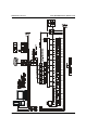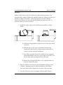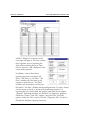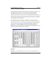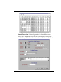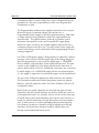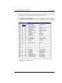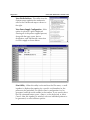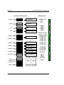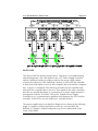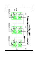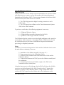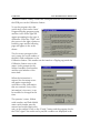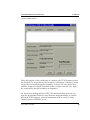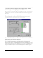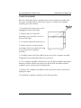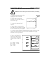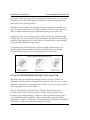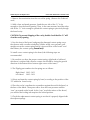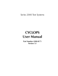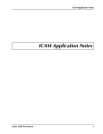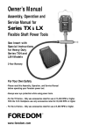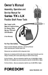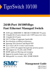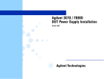
1
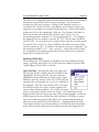
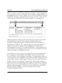
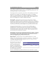
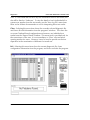
Series 2040D Test Systems
2040D
Maintenance
Manual
Part Number #4200-0181
Version 1.0
Table Of Contents
System Overview ......................................................................................... 3
SYSTEM MAINTENANCE OVERVIEW ................................................ 5
Selftest & Calibration .................................................................................. 7
SELFTEST AND CALIBRATION OVERVIEW ........................................ 8
Purpose Of Calibration ........................................................... 8
When To Calibrate .................................................................. 8
SELFTEST ........................................................................................... 9
Selftest Failure Analysis ......................................................... 14
CALIBRATION ................................................................................. 16
Diagnostics................................................................................................ 19
DIAGNOSTIC TOOLS ..................................................................... 20
SelfTest EXaminer (STEX) for Microsoft Windows 95 ......................... 20
Overview .............................................................................. 20
Creating the Diagnostic File for STEX ..................................... 20
Analyzing Selftest Data .......................................................... 21
TRMAN (Tester Resource Manager) .................................................. 25
Menu Bar ............................................................................. 25
TESTHEAD - PATCHBOARD - UUT P/S BUILT-IN DIAGNOSTICS .... 31
Breakers and Test Points ........................................................ 32
LED Indicators ...................................................................... 32
GPIB/HPIB POWER SUPPLIES ......................................................... 37
Troubleshooting Hewlett-Packard Power Supplies.................. 37
Certification .............................................................................................. 43
CERTIFICATION .............................................................................. 45
Setup .................................................................................... 45
Module Repair & Replacement ................................................................. 49
REPAIR AND REPLACEMENT PROCEDURES ................................... 50
COMPUTER ASSEMBLY ........................................................ 51
INTERNAL AND PATCHBOARD P/S OVERVIEW ............................. 52
TESTHEAD & PATCHBOARD P/S REPLACEMENT ................. 53
+5VDC Testhead Power Supply ............................................ 54
UUT POWER SUPPLIES - Description .............................................. 56
UUT POWER SUPPLY CONTROLLER REPLACEMENT .......... 57
UUT POWER SUPPLIES........................................................ 58
GPIB/HPIB POWER SUPPLIES .............................................. 59
UUT - GPIB/HPIB P/S DISCONNECT AT TEST BAY ............... 60
CIRCUIT BOARD REPLACEMENT ................................................... 61
CONTACT SPRING REPAIR ............................................................. 63
USE OF PATCHBOARD SPRING REMOVAL TOOL (0000-2746) ...... 64
CONTACT SPRING REPLACEMENT (Conventional Method) . 65
Series 2040 Maintenance Manual V2.00
Maintenance Overview
System Overview
Series 2040 Test System
3
Maintenance Overview
4
Series 2040 Maintenance Manual V2.00
Series 2040 Test System
Series 2040 Maintenance Manual V2.00
Maintenance Overview
SYSTEM MAINTENANCE OVERVIEW
The Series 2040 Test System has been designed with extensive diagnostics and
self testing capabilities. Each module and circuit board includes additional
circuitry for calibration and self testing programs. In addition, a Selftest
Assembly is provided to calibrate and functionally test every component in the
test system. This assembly attaches to the fixture interface to provide the best
accuracy and reliability for calibration and self-diagnostics.
The Certification program uses a Calibration station containing a Digital
Voltmeter (DVM) and Universal Counter/Timer, which are certified by the
National Institute of Standards and Technology as a “Transfer Standard,” to
calibrate the internal precision references of the tester. The Selftest Assembly
uses a 18-bit D/A converter (TDAC) as an internal precision voltage standard.
The internal precision time standard is a Temperature Compensated Crystal
Oscillator located on the Time Measurement System board.
The Calibration and Selftest routines calibrate the remainder of the system to
the tester’s internal precision references. Calibration constants are derived
during Calibration. These constants are used during runtime to maintain
system accuracy. The Calibration constants are stored on the hard drive and
reloaded at powerup. Complete system auto-calibration is achieved without
any pots to adjust.
The Selftest programs use the Selftest Assembly to test all circuits to their
published specifications, and assure that all paths and modules are functional.
The System Maintenance guide is written for troubleshooting to the module
and circuit board level.
The tester shall be disconnected from all power sources
before it is opened for any adjustment, replacement,
maintenance or repair. If service repairs performed under
power become necessary, the repairs shall be performed
by a skilled technician who is aware of the hazard
involved.
Series 2040 Test System
5
Maintenance Overview
6
Series 2040 Maintenance Manual V2.00
Series 2040 Test System
Series 2040 Maintenance Manual V2.00
Selftest & Calibration
Selftest & Calibration
Series 2040 Test System
7
Selftest & Calibration
Series 2040 Maintenance Manual V2.00
SELFTEST AND CALIBRATION OVERVIEW
Calibration on the Series 2040 Functional Test System is completely
automated. All calibration is based on high precision references built into the
system Testhead and the Selftest Assembly. A high precision Temperature
Compensated Crystal Oscillator (TCXO) on the Time Measurement System
Board (TMS) is used as a frequency/time reference. A precision digital to
analog converter (TDAC) contained within the Selftest Assembly is used as a
voltage reference for system calibration.
Purpose Of Calibration
Calibration of the functional tester is necessary to obtain gain and offset terms
for all signal paths that exist within the system, and to determine timing for the
MDE’s (Measurement Display Electronics) sweeps, delays, triggers, and
measurement mark. Since potentiometers are used in only a few instances
where factory calibration is required, the majority of the calibration is done by
taking measurements and calculating calibration terms which can be
referenced at a later time. These terms are used by the hardware functional
calls to account for gains, offsets, and timing discrepancies, and their use is
transparent to the user.
In all calibration programs, limits are set on what values any given calibration
term may take on. If a calculated value is outside of the allowable range, a
failure will result and be displayed/printed to the designated output device .
When To Calibrate
Selftest is the best guide to determine if calibration is required. The battery of
Selftest programs is designed to test all functions of the 2040 to their
specifications. If any failures occur during Selftest (especially borderline
failures), calibration should be carried out before proceeding to troubleshoot
the system.
Running through Selftest periodically can tell you if calibration is or is not
required. If you find that all Selftest programs run without failures, there is no
need to recalibrate any portion of the tester. The recommended guideline is to
calibrate every 3 months.
Whenever a temperature change of more than five (5) degrees Celsius occurs
or a Testhead board swap is made, the 2040 should be recalibrated.
8
Series 2040 Test System
Series 2040 Maintenance Manual V2.00
Selftest & Calibration
SELFTEST
Selftest on the Series 2040 Test System is an automated procedure. The
programs that comprise Selftest are organized under the Selftest Executive in a
test menu called “Functional”. These programs exercise the hardware
functions available to the user through the hardware functional calls. To
perform Selftest, proceed as follows:
1) Install the Selftest unit on the Patchboard assembly as shown
below:
A) Pull the locking handle towards the front of the unit until it
is vertical.
B) Slide the pins on the rear of the Selftest unit into the
Patchboard and rotate the Selftest unit forward until it is
vertical, and sets into the Patchboard.
C) The ribbon assembly should be installed in the receptacle
behind the Selftest, with the colored edge of the ribbon on
the left side, while viewing the front of the unit.
D) Rotate the locking handle back to it’s original position to
lock the Selftest into place.
2) Enter the Selftest Executive by selecting (double-clicking on) the
“SelfExec” program from the Windows Explorer. The Selftest
Executive menu will be displayed as shown on the next page.
3) From the File menu, select Configure, and the small “Report
Series 2040 Test System
9
Selftest & Calibration
Series 2040 Maintenance Manual V2.00
Utilities” dialog box in shown on the
next page will appear. This box contains
three separate ways of reporting the
data collected during the tests. Data
may be stored to a file, displayed on the
screen and/or printed.
In addition, each of these three
reporting functions can report “All
Data”, “Fail Data” or “No Data”. “All
Data” includes all of the pass or fail
sequences from the test. “Fail Data”
includes only information on the tests
that failed. “No Data” disables that reporting function. To select, merely
use the mouse to check or uncheck each reporting function. If a
reporting device is unchecked, the options under that device appear
“ghosted”, indicating that they are disabled. For diagnostic purposes,
enable the “Printer” and “File” options, and select the “Fail Data”
option. Under the “File” section, click the “Diagnostic File” check box.
Disable the Window reporting functions.
10
Series 2040 Test System
Series 2040 Maintenance Manual V2.00
Selftest & Calibration
4) Once the type(s) of reporting is completed, click on “OK” to return
to the Selftest Executive menu. Select “Functional” from the
Selftest Executive screen, and the Functional menu will appear as
shown below.
The Functional test menu has been organized so that tests closely
related are blocked together in groups. If only one test is to be run,
use the mouse to select that particular test. If a related group of
tests is to be run, they may be selected using only the mouse. For
example, if the Measurement Display Electronics group is to be
selected, place the mouse pointer on test #30 and hold the left
button down, and drag the mouse down to test #38. The entire
MDE group is now selected. If a random series of tests is desired,
place the mouse pointer on the box under “Run sequence”. When
the Windows text tool appears, click the left mouse button. At the
blinking cursor, any sequence of tests can be entered. The test
numbers, however, must follow this syntax:
‘E’ (Execute) signifies the beginning of a sequence or acts as a
separator between sequences.
Series 2040 Test System
11
Selftest & Calibration
Series 2040 Maintenance Manual V2.00
“:” (Colon) signifies that the following number indicates the amount
of iterations to perform of the previous sequence.
‘,’ (Comma) shares the definition of ‘E’ as a separator between
sequences.
‘-’ (Dash) signifies inclusive or ‘through’.
EXAMPLE: E1-3:5,6-100:2,1-5
This sequence executes tests 1 through 3 five times, tests 6 through
100 two times, and tests 1 through 5 once.
If a single test or a group of selected tests is to be run once, 10
times, or 100 times, use the mouse to select the appropriate button
on the upper left. If the test or group is to be run at some other
number, place the mouse pointer in the box to the direct left of the
stop button, and the Windows text tool will appear in place of the
mouse pointer. Click the left mouse button while texttool is
displayed in the box, and a blinking cursor appears in the box. The
user can now enter any number from 1 to 999 for the number of
times a test should run.
For diagnostic purposes, click
the mouse button on the small
box in the upper left corner of
the menu next to “All Tests”.
Select the “1" button, and the
program will run all of the
functional tests once, while reporting the data to wherever it was
directed from the ”Report Utilities" box. For diagnostics this path
should include the “File” and “Printer” categories, and the “Fail
Data” and “Diagnostic File” options.
5) If any of the Functional programs fail, check these common
problems:
SELFTEST ASSEMBLY IMPROPERLY INSTALLED - Check to make
sure the assembly is properly installed on the Patchboard. Also,
12
Series 2040 Test System
Series 2040 Maintenance Manual V2.00
Selftest & Calibration
check the Selftest assembly’s cable for damage.
UUT POWER SUPPLIES OFF - Make sure the UUT Power Supplies
are on.
TESTHEAD POWER SUPPLY FAULT - Check the Testhead Power
Supply Controller’s indicator LEDs. If any of the LEDs are not lit,
reset the system and recheck.
MISALIGNED PINS ON PATCHBOARD RECEIVER - Remove the
Selftest Assembly and carefully inspect the alignment of the
Patchboard receiver pins. Adjust any pins that are misaligned,
remount the Selftest Assembly, and re-test.
After the common problems have been eliminated, a failure in
Functional Selftest can indicate a hardware problem. Since a failure
in Functional Selftest could also be caused by calibration,
recalibrate the unit and run Functional Selftest again. If calibration
or Functional Selftest fails now, a hardware problem most likely
exists. Refer to the Selftest Failure Analysis on the next two pages.
Series 2040 Test System
13
Selftest & Calibration
Series 2040 Maintenance Manual V2.00
Selftest Failure Analysis
1)
2)
3)
4)
5)
6)
7)
8)
9)
10)
11)
12)
13)
14)
15)
16)
17)
18)
19)
20)
21)
22)
23)
24)
25)
26)
27)
28)
29)
30)
31)
32)
33)
34)
35)
36)
37)
38)
39)
40)
41)
42)
43)
44)
45)
14
Test Name
SELF_dig-f
th_config_tst
ams_dig_f
ams_mode_f
ams_sig3_f
#1
#2
#3
Selftest
TH Cont/CPU TH P/S Cont
Testhead configuration does not match the stored configuration.
AMS
TH Cont/CPU TH P/S Cont
AMS
MSP/ISO
ASB
AMS
MSP/ISO
TH P/S Cont
arly_dig_f
arly_f
afet_rft_f
Arly/AFET
Arly/AFET
AFET
TH Cont/CPU
RMUX
RMUX
TH P/S Cont
AMS
AMS
mrly_dig_f
mrly_f
MRLY
MRLY
Selftest
RMUX
TH Cont/CPU
AMS
rmux_dig_f
rmux_f
rmux_prt_f
RMUX
RMUX
RMUX
TH Cont/CPU
AMS
AMS
TH P/S Cont
Selftest
MDE
arb_mem_f
arb_brst_f
arb_ext_f
arb_freq_f
arb_mon_f
arb_ref_f
da_ref_f
ASB
ASB
ASB
ASB
ASB
ASB
ASB
TH Cont/CPU
AMS
AMS
AMS
AMS
AMS
AMS
TH P/S Cont
MDE
MDE
MDE
MSP/ISO
MDE
MSP/ISO
mde_dlmd_f
mde_dltm_f
mde_expm_f
mde_freq_f
mde_mrkp_f
mde_msmk_f
mde_pmes_f
mde_tgfl_f
mde_tglv_f
MDE
MDE
MDE
MDE
MDE
MDE
MDE
AMS
AMS
TMS
TMS
TMS
TMS
TMS
TMS
TMS
MDE
MDE
AMS
AMS
AMS
AMS
AMS
AMS
AMS
TMS
TMS
tms_dig_f
tms_evnt_f
tms_test_f
TMS
TMS
TMS
TH Cont/CPU
MDE
MDE
TH P/S Cont
AMS
TH P/S Cont
dio_f
DIO
Selftest
TH P/S Cont
Series 2040 Test System
Series 2040 Maintenance Manual V2.00
46)
47)
48)
49)
50)
51)
52)
53)
54)
55)
56)
57)
58)
59)
60)
61)
62)
63)
64)
65)
66)
67)
68)
69)
70
71)
72)
Selftest & Calibration
dio_ext_f
DIO
Selftest
TH P/S Cont
iamp_dig_f
inst_f
amp_cmrr_f
isoamp_f
INST
INST
INST
MSP/ISO
TH Cont/CPU
ASB
RMUX
ASB
TH P/S Cont
AMS
AMS
AMS
pwr_mon_f
ptest_f
th_iso_f
Power Supply
TH P/S Cont
MSP/ISO
UUT Controller AMS/RMUX
Selftest
Scope Connected?
Internal coax short?
msp_ser_f
MSP
TH Cont/CPU
TH P/S Cont
ocio_dig_f
ocio_f
ocio_rail_f
OCIO
OCIO
OCIO
TH Cont/CPU
Selftest
Selftest
TH P/S Cont
TH Cont/CPU
TH Cont/CPU
adio_f
adio_ext_f
ams_int_f
ADIO
ADIO
AMS
Selftest
Selftest
MDE
TH Cont/CPU
TH Cont/CPU
TH Cont/CPU
dms_dig_f
dms_mem_f
DMS
DMS
Selftest
TH Cont/CPU
TH Cont/CPU
TH P/S Cont
psc_dig_f
PSC
Any other Trigger Matrix board.
Series 2040 Test System
15
Selftest & Calibration
Series 2040 Maintenance Manual V2.00
CALIBRATION
Whenever a Testhead board is
replaced, or any time that Selftest
determines a failure, a calibration
must be performed. If a unit
passes the complete Functional
Selftest routine, a calibration is
not necessary. When Calibrate is
selected from the Selftest
Executive, the screen shown to
the right is displayed.
The Calibrate menu operates
under the same basic rules as the
Functional menu. For installation
purposes, use the mouse to select the “All Tests” box, and select the “1"
button for the number of times to be run. (See page #6). Ensure that the
Printer and Fail Data are selected, so that any failures will be printed
automatically.
The following is a list of the calibration programs located in the Calibrate
menu in the Selftest Executive, with the three most likely boards or assemblies
that could cause failures:
Test Name
#1 AMS_RMUX_c
#2 AMS_SIG3_c
#3 AMS_DIFF_c
#4 DMS_c
#5 ARB_v_c
#6 DA_v_c
#8 DIO_c
#9 ADIO_c
#10 ADIO_dac_c
#12 MDE_c
#13 MDE_TGDC_c
#15 POWER_c
#17 ISOAmp_c
16
#1
#2
AMS
RMUX
AMS
MSP/ISO
AMS
RMUX
DMS
ASB
MSP/ISO
ASB
MSP/ISO
DIO
TH CONT/CPU
ADIO
TH CONT/CPU
ADIO
AMS
MDE
TMS
MDE
TMS
UUT Cont
AMS/RMUX
MSP/ISO
AMS
#3
MSP/ISO
RMUX
ICAM
AMS
AMS
Selftest
Selftest
RMUX
AMS
AMS
Selftest
RMUX
Series 2040 Test System
Series 2040 Maintenance Manual V2.00
Selftest & Calibration
Any type of failure during calibration could indicate a hardware problem. If a
failure during Functional was the reason that a calibration is being run, refer to
the Selftest Failure Analysis sheet on page 8 of this section.
Series 2040 Test System
17
Selftest & Calibration
18
Series 2040 Maintenance Manual V2.00
Series 2040 Test System
Series 2040 Maintenance Manual V2.00
Diagnostics
Diagnostics
Series 2040 Test System
19
Diagnostics
Series 2040 Maintenance Manual V2.00
DIAGNOSTIC TOOLS
SelfTest EXaminer (STEX) for Microsoft Windows 95
Overview
The STEX program may be used to help graphically interpret the
results of any diagnostic output file generated by Digalog System’s
SelfExec program run on the Series 2040 testers. STEX uses the results of the
diagnostic output file to show the configuration of the tester and evaluate
possible problems with the tester resources based on failed test data and/or
system errors during testing. STEX will use these results to ‘decide’ what the
top three most likely resource problems are in the tester, based on Selftest
output information. These results will be shown graphically on the STEX
interface, highlighting and identifying the potentially problematic resources in
the tester.
STEX can be very useful in aiding an operator who is troubleshooting possible
problems in the Digalog testers by providing a graphical depiction of the
location of potentially faulty tester resources. These resources include all
Testhead boards, the Testhead power supplies, the variable power supplies
and their controller modules, the computer with its Testhead controller card,
and the Selftest unit itself.
Creating the Diagnostic File for STEX
To use STEX to analyze Selftest data, the proper information must be recorded
in the Selftest output file first. A new user selection under SelfExec’s output
configuration has been added to provide this information. To obtain a
diagnostic file for use in STEX, follow these steps
when running SelfExec:
1) Under the ‘File’ menu, select
‘Configuration’.
2) On the configuration form under ‘File
Options’, select either ‘Fail Data Only’ or ‘All
Data’ and select ‘Diagnostic’.
3) Run the desired calibration and function
tests.
20
Series 2040 Test System
Series 2040 Maintenance Manual V2.00
Diagnostics
Selection of the ‘Diagnostic’ option for file output will create a file with all the
information required by STEX to analyze the system. This information
includes the tester type being run, a listing of the Testhead resources as
recorded in the ‘resource.ini’ file or the Registry, and a listing of all tests run
along with any problems encountered during the tests. These results will be
written into a file in the ‘digalog\bin\’ directory. The filename is the date on
which the test was run with the file extension ‘.dxx’, where ‘xx’ is an
incrementing number starting at ‘01’ and going through ‘99’. For example, if
the diagnostic file was written on January 20, 1997, the file name would be
‘jan2097.d01’. If a second file were created on the same day, its name would
be ‘jan2097.d02’, and so on. The first SelfExec file written each day would
carry the extension ‘.d01’. If SelfExec’s file option is not set to ‘Diagnostic’, the
file extension would be ‘.001’, ‘.002’, and so on. These files do not contain
the configuration information required by STEX and will not be accepted as
proper files for analysis by STEX.
Analyzing Selftest Data
When starting the STEX program, the graphics show the Testhead as being
empty. Under the menu item ‘File’ are the selections: Open for EXam, View
Log File, Report Details, Close, and Exit.
Open for EXam - Selecting this menu item opens up a
file selection window showing the files available in the
‘digalog\bin\’ directory with the ‘.dxx’ file extension.
Highlight the desired filename and Click on the ‘Open’
button to select for analysis under STEX. STEX will then
open that file, and examine it to see if it is a valid file for
this program. If the file is not valid for STEX, a message
box will inform the user of this, and the graphics will
return to their default condition. If it is valid, the tester
resource information will be read in for analysis. The boards listed in the
Registry will be placed in the proper slots in the Testhead graphic and the file
will be inspected for any fail data from the tests listed. If fail data or system
errors are found, the program will analyze those results using information
about the tests located in the STEX database — ‘digalog\include\stex.mdb’.
The program will then use this information to calculate the three most likely
tester resources that could cause the problems found in this diagnostic file.
Series 2040 Test System
21
Diagnostics
Series 2040 Maintenance Manual V2.00
All tester resources, by default, are either gray-colored or on gray background.
The one to three resources calculated to be most likely causing the fault(s) will
be highlighted in red. Also, the ‘Results:’ box on the lower portion of the form
displays the information regarding these three tester resources. If the resource
is a board in the Testhead, an arrow with a number 1-3 according to its
relative importance (1 being greatest) will point to the location of the board.
An information box with the same number will display the board’s
description, Digalog part number, and serial number (if this information is
available in the diagnostic file.) If the tester resource is not a board in the
Testhead, the resource’s graphic will be highlighted in red with a label
indicating which ‘Choice #’ it is in relative importance. The information box
with the ‘Choice #’ information will have the resource’s description and other
optional information regarding that resource.
If the SelfExec test ‘TH_config_test’ has logged fails in the current diagnostic
file, a message box will be shown informing the user that this fault exists.
Also, the ‘Results:’ box will display the message: “Config problems found” on
a red background. The configuration of the Testhead will be displayed, but no
specific tester resources will be tagged as being at fault as a result of this file’s
analysis. The test ‘TH_config_test’ examines and compares the contents of
the Testhead to the recorded listing in the Registry. If a problem is found with
this test, it cannot be automatically known where the source of the problem is
without further investigation. Therefore, the user should refer to the Tester
Resource Manager (TRMAN) section of this manual to proceed in
troubleshooting this problem.
22
Series 2040 Test System
Series 2040 Maintenance Manual V2.00
Diagnostics
If any failure(s) or problem(s) are found in a valid diagnostic file, the menu item
‘Report Details’ will be enabled to show some details about those tests. See
item ‘Report Details’ for more information.
If the diagnostic file is examined, and no fails or other problems were found
with this test, the ‘Results:’ box will display the message: “No Problem
Found” on a green background. The proper configuration for the Testhead
will be displayed, but the menu item ‘Report Details’ will be disabled, since
there are no failing tests on which to display information.
View Log File - Selecting this menu item opens a file selection window
showing the available files, similar to the ‘Open for EXam’ item. Selecting a
filename here will start the Microsoft Windows text editor program ‘WordPad’
and open the diagnostic file for viewing. Here, individual test results may be
viewed to provide further possible insight into any problems with the tester.
Viewing the individual failures of a test may aid in troubleshooting an
individual board. Examining any system error messages and referring to
documentation for the source and/or meaning of the error may also help in
resolving the problem with the tester resources. While viewing this file, the
user may also elect to print the file contents.
IMPORTANT!! The file being examined SHOULD NOT be edited. Changing
any information in these files could render the information inaccurate or
useless for diagnosing any problems with the tester.
Report Details - This menu item is only available while there is a valid
diagnostic file with fail information opened for examination. ‘Report Details’
is a listing of the individual Selftest programs that show at least one fail or
system error during its execution.
Selecting this menu item will
bring up a separate window
with a list of the failed test
programs. This list gives the
name of the Selftest which had
the problem, the slot number of
the board being examined by
that test, and whether the problem with the test was a test fail or a system
Series 2040 Test System
23
Diagnostics
Series 2040 Maintenance Manual V2.00
error. If a test listed did not have any slot information listed in the results, the
slot will be listed as ‘Unknown’. To view the details of each individual fail or
system error number from the test results, use the ‘View Log File’ menu item.
Refer to the Selftest documentation to aid in interpreting these test results.
Close - Selecting this menu item closes the currently selected diagnostic file
and clears all result information from the program’s windows. This clears the
on-screen Testhead board configuration and removes any individual test
results from the ‘Report Details’ window. This menu item is provided only for
the convenience of the user. It is not mandatory to ‘Close’ one test before
opening another for exam. However, it may be used to provide an obvious
separation in the examination of different test result sets.
Exit - Selecting this menu item closes the current diagnostic file, clears
configuration information from the program, and closes and exits the program.
24
Series 2040 Test System
Series 2040 Maintenance Manual V2.00
Diagnostics
TRMAN (Tester Resource Manager)
The Tester Resource Manager is used to track and manage the tester resources
including all the boards in the Testhead and the UUT power supplies.
Information about these resources can be automatically generated or
manually defined, and is used to generate a Patchboard Interface Map and
define the pin locations of these resources at the Patchboard. This information
can be saved to a project specific file called resource.ini and can be used by
other Digalog System’s applications.
Specifically, the software is capable of printing out a “Patchboard Map”
containing Patchboard pin mnemonics by either automatically interrogating
the tester for its resources, or by asking the programmer to define the tester’s
resources. When the configuration is performed manually, it allows the
programmer to configure additional resources beyond what the tester
physically contains. In this manner, a programmer has the additional resources
to generate programs and fixtures for any tester.
Menu Bar
File Menu - The TRMAN File menu is similar to the standard Windows file
Series 2040 Test System
25
Diagnostics
file in the \Digalog\include\ directory.
Series 2040 Maintenance Manual V2.00
menu. It has selections for a New
configuration, Load an existing
configuration, Save a configuration, Save
an existing configuration As another file,
and Exit. The Print Utility as shown
below will be discussed later in this
section. For the purposes of this
explanation, the file being used for
illustrations is the standard resource.ini
Options Menu - When the Options menu is
selected, a pull-down menu will be displayed
prompting for a choice of the following: Automatic generation, Link to tester, Manual Generation, View pin Definitions, and View
Testhead configuration. Each of these options,
along with the Print utility from the File menu,
will be briefly discussed.
Link to Tester - This item will toggle the link between the application
and a tester. When checked, the application assumes a Testhead is
present and enables Automatic generation. When using Tester
Resource Manager on a development computer that is not connected
to a Digalog tester, this item should never be checked as it could lead
to corruption of certain memory locations.
Automatic Generation - If Automatic Generation is selected, the
program scans the tester for its resources, and then updates the map of
the Patchboard as shown on the next page. Tester resources required
to generate the Patchboard map plus any other tester resources can
also be saved to a resource file on the hard drive (resource.ini) stored in
the Registry, or printed out.
All programmers writing code for the system should be familiar with
this map, since it is the actual physical configuration of the
Patchboard.
26
Series 2040 Test System
Series 2040 Maintenance Manual V2.00
Diagnostics
Manual Generation - If Manual generation is selected, the screen
below will be displayed. Note that the Power Supply Distribution
board is always in slot 0 and therefore does not show in the Testhead
Series 2040 Test System
27
Diagnostics
Series 2040 Maintenance Manual V2.00
configuration table. From this utility, any system configuration may be
generated. It is the users responsibility to make sure the generated
configuration is valid.
The Programmable variable power supplies (maximum of five) may be
defined in terms of maximum voltage and current once a
Programmable Power Supply is selected (up/down button). With Volts
or Amps selected, the jog shuttle located to the right modifies the
selected value. The option buttons under the jog shuttle control
determine what position in the serial loop that the supply being
defined occupies. However, the variable supplies must be filled in a
contiguous manner from #0 to #4. The spin control on the upper left
corner of the dialog is used to determine which programming channel
is being configured.
If a GPIB or HPIB power supply is being defined or added, the channel
and type can be selected and the upper right of the dialog changes to
allow the programmer to select a power supply type, a GPIB/HPIB
Device number, and what Relay Control board will be used. The spin
control on the middle left of the dialog (Patchboard Connection) is
used to define which of the five Patchboard connections are connected
to which supply, or if a GPIB/HPIB supply will use an external output
(i.e. the supply’s output does not physically appear on the Patchboard.)
The rest of the Testhead is displayed in table format by slot number.
The Description and Board Number drop-down menus are directly
linked to, and will modify the table. The Clear All button will clear all
configuration items.
Board Codes are specific identifiers for the particular type of board
selected for that slot. Board Numbers are used to define the resources
of that particular board. For example, if there are two of the same type
of board in the system, board numbers zero and one, the resources of
board one will be numbered over and above those of board number
zero. In other words, for a Relay Multiplexer Board containing sixtyfour channels, board zero channels would be labeled zero through
sixty-three and board one channels would be labeled sixty-four
through one hundred and twenty-seven.
28
Series 2040 Test System
Series 2040 Maintenance Manual V2.00
Diagnostics
The table is directly linked to the slot drop-down menu, therefore any
slot changes in either place will be reflected in the other.
View Testhead Configuration - This utility displays the entire Testhead
configuration in an organized format. An example of a typical Testhead
configuration is shown below.
Series 2040 Test System
29
Diagnostics
Series 2040 Maintenance Manual V2.00
View Pin Definitions - This utility from the
Options menu explains the mnemonics
used in the Patchboard map as shown to
the right.
View Power Supply Configuration - If this
option is selected, a grid is displayed
showing all of the power supplies present,
along with the type, name, device
designation, and Patchboard connection
for each supply as shown below.
Print Utility - When this utility is selected from the File menu, a small
inputbox is displayed prompting for a specific serial number for the
printout to be generated. If a specific tester’s configuration is to be
generated, enter the serial number in the textbox. If not, merely select
the OK command button, press <Enter> on the keyboard, or select
Cancel. After this inputbox is satisfied, select an individual printout to
be generated, or select all three options.
30
Series 2040 Test System
Series 2040 Maintenance Manual V2.00
Diagnostics
TESTHEAD - PATCHBOARD - UUT P/S BUILT-IN DIAGNOSTICS
When a malfunction is suspected in either the Testhead Internal or
Patchboard Power Supply system, the LED status indicators should be
examined. The top LEDs are labeled for their respective power supplies as
shown on page 14. The legend for the four lower LEDs is shown below. In
case of a power supply malfunction, the power supply that has shut down first
will be indicated by its respective LED being extinguished.
If you are diagnosing the case of no power at the Patchboard, and the status
indicators, the lower four LEDs, are all lit, then an over/under voltage fault has
occurred in a Patchboard power supply. The power supply causing the fault
will have it’s respective LED extinguished. Power could also have been
removed from the Patchboard without generating a fault condition. In this
case, the reason that the power has been removed is indicated by one or two
of the lower four status LEDs being extinguished.
CASE
Power Call
TCLEAR
Patchboard removed
UUT Power Fault
PROX
PBON
Ext.Fault
Reset
on
on
off
on
off
off
on
on
on
on
on
off
on
off
on
on
When a power supply cannot be restored by resetting the unit, the circuit
breaker for the offending supply should be checked for continuity. A graphic of
the circuit breakers on the edge of the Testhead Power Supply Controller
board is shown on page 14 of this section. If any of these breakers continually
trips, the associated power supply must be replaced.
Series 2040 Test System
31
Diagnostics
Series 2040 Maintenance Manual V2.00
Breakers and Test Points
+ 5VDC TH
+ 48V TH
DC1+
DC1-
- 40VDC TH
+ 40VDC TH
- 19VDC TH
+ 19VDC TH
- 15VDC TH
+ 15VDC TH
- 5.2VDC PB
TP17
TPA17
TP16
TPA16
TP14
TPA14
TP13
TPA13
LED Indicators
+ 5VDC TH
+ 48V TH
GPIB 3
GPIB 2
GPIB 1
GPIB 0
DC1+
DC1-
TP19
TPA19
TP18
+/- 40VDC TH
TPA18
TP8
TPA8
TP7
TPA7
TP6
TPA6
TP5
TPA5
TP4
TPA4
- 19VDC TH
+ 19VDC TH
+ 5VDC TH
+/- 15VDC TH
Patchboard Power
TP3
Common
- 15VDC PB
+ 15VDC PB
+ 5VDC PB
32
TPA3
TP2
TPA2
K2
+ 5VDC
PB
+48VDC TH
DC1 DC1 +
K1
+/- 15VDC
PB
- 40VDC (ICAM)
+ 40VDC (ICAM)
- 5.2VDC TH
+ 5VDC TH
- 19VDC TH
+ 19VDC TH
- 15VDC TH
+ 15VDC TH
- 15VDC PB
+ 15VDC PB
+ 5VDC PBF
HP Fault
PROX
PBON
Ext. Fault
Reset
TP1
TPA1
Series 2040 Test System
Series 2040 Maintenance Manual V2.00
Diagnostics
FAULT LOOP
The Series 2040 Test System incorporates a “fault loop” for troubleshooting
and self-diagnostics. The cable between the UUT Power Supply Controller
and the Testhead, besides providing a path for the power supply output,
contains the fault loop. If the fault loop is broken, it will cause the controller
to shut down and report an error to the computer (the next time the computer
tries to give it a command). The fault loop is broken by the controller itself
whenever the controller detects an error. This signals to the other controllers
that they too should shut down. If a controller for a power supply channel is
unresponsive and the “Ext.Fault” LED on the Testhead Power Supply
Controller is on, a communication problem exists between the CPU and the
controller. If the LED is out, the fault loop is probably broken.
The power supplies may be isolated for diagnostics as shown in the following
pages. If a supply is isolated and fails to power up, it is most likely the
problem. If a supply is isolated and powers up, it can b eliminated as the
cause of the failure.
Series 2040 Test System
33
Diagnostics
34
Series 2040 Maintenance Manual V2.00
Series 2040 Test System
Series 2040 Maintenance Manual V2.00
Series 2040 Test System
Diagnostics
35
Diagnostics
36
Series 2040 Maintenance Manual V2.00
Series 2040 Test System
Series 2040 Maintenance Manual V2.00
Diagnostics
GPIB/HPIB POWER SUPPLIES
The Series 2040 Test System may also contain one or more GPIB/HPIB Power
Supplies. These supplies communicate with each other and the computer via
an IEEE-488 bus. In addition, they use a Fault/Inhibit loop for voltage/current
protection and this loop also connects to the Testhead Power Supply
Controller.
Some of these supplies may have more than one output channel. In these
situations, each separate output of each GPIB/HPIB supply is assigned its own
channel or unit number. Programming is accomplished using Digalog’s
PowerUUT functional call. Over/under voltage/current limits for these supplies
and channels are listed in the “resource.cat” file. For programming purposes,
these power supplies act in the same manner as the Digalog UUT Product
Power Supplies.
Troubleshooting Hewlett-Packard Power Supplies
The fault/inhibit loop for the Hewlett Packard power supplies links each HP
power supply serially with each other and with the PSC board. It is completely
independent of the UUT P/S controllers’ (external) fault loop and the fault
loop for each non-HP GPIB power supply.
The PSC board will recognize a fault generated by the HP fault/inhibit loop
only if the registered power supply configuration (set up by TRMAN) contains
at least one HP power supply whose “resource.cat” entry has its “Fault
Capable” property set to “1.”
The “HPF” LED on the PSC board will turn off whenever an HP power supply
has either detected an internal error condition, such as overvoltage, or has
been “faulted” by the PSC board, but only after a HP power supply has been
programmed following a Testhead power-up or the TClear event.
The fault signal driving the HPF LED on the PSC is not latched. Also, if the
reset jumper shunt on the PSC board is installed, only the Proximity-Switch
LED will turn off when the Patchboard fixture handle is disengaged. It will
then turn back on when the handle has re-engaged. The PSC board will drive
its HP fault/inhibit loop connection low every time that it detects a fault from
any source whether or not any HP power supplies are registered or even
present.
Series 2040 Test System
37
Diagnostics
Series 2040 Maintenance Manual V2.00
For a system containing “n” number of HP power supplies, the PSC board
drives the +Inhibit (input) line of HP P/S #n low relative to its -Inhibit (input)
line. When this power supply detects that its +Inhibit input signal is low, then
it drives its +Fault (output) signal low relative to its -Fault (output) signal.
These fault output lines are connected to the inhibit input connections of HP
P/S #(n-1). Upon its detection that HP P/S #n has driven its +Inhibit (input)
signal low, HP P/S #(n-1) will then “fault” HP P/S #(n-2) using its fault (output)
connections. Thus, each HP P/S in the fault loop will “fault” the power supply
preceding it in the loop all the way to HP P/S #0. The Fault (output) lines of
HP P/S #0 connect to the PSC board, which allows that power supply to
signal the PSC board that an error has been detected by one of the HP power
supplies.
Upon detection of an internal error condition, such as overvoltage, or the
external inhibit (input) signal, the HP power supply will program its output(s)
to 0.0V @ 0.0A, disable its output(s), and assert its fault (output) signal.
If an HP power supply detects an internal error condition, it will then drive its
+Fault (output) line low to signal the next HP power supply positioned below
it in the loop. Eventually, the “fault” signal will reach HP P/S #0, and it, in
turn, will trigger the PSC board. The PSC board will then latch HP P/S fault
condition and drive all of its fault output connections, including that for the
HP power supplies. This will “fault” all of the HP power supplies positioned
after the one which detected the internal error condition. The initial faulting
HP power supply will also have its +Inhibit (input) connection driven low by
the power supply following it.
To determine which HP power supply detected an internal error condition,
press the “Local” button and then the “Prot” button on each HP power
supply. All of the HP power supplies that were “faulted” by their following
brethen via their inhibit (input) lines will display the letters “RI,” which stands
for “Remote Inhibit,” in its LCD display. The single HP power supply that
displays something other than “RI” in its LCD display is the power supply that
detected an internal error condition. Consult its operating manual to
determine the cause of the internal error condition.
If some or none of the HP power supplies are disabled via their fault/inhibit
loop connections when the PSC board detects a fault from some other source,
such as the proximity switch, proceed with the following troubleshooting
procedure.
38
Series 2040 Test System
Series 2040 Maintenance Manual V2.00
Diagnostics
1) Verify on the relay controller board (0000-5X44) that pin #3 relative
to pin #4 of connector P3 (PSC Port) is low or at a logic “0.” If not, a
problem exists on the PSC board, in the fault/inhibit cable from the
PSC board to connector P3, or with connector P3 .
2) Otherwise, verify that pin #3 relative to pin #4 of connector P5
which mates to the first relay disconnect board is low or at a logic “0.”
If not, a problem exists on the relay controller board.
3) Otherwise, on the first relay disconnect board, verify that pin #3
relative to pin #4 of connector P1 (which mates to the relay controller
board) is low or at a logic “0.” If not, a problem exists either with
connector P1 or else with connector P5 on the relay controller board.
4) Otherwise, verify that pin #3 relative to pin #4 of connector P3
(which mates to the next relay disconnect board) is low or at a logic
“0.” If not, a problem exists between connectors P1 and P3 on the
relay disconnect board.
5) Otherwise, on the second relay disconnect board, verify that pin #3
relative to pin #4 of connector P1 (which mates to the first relay
disconnect board) is low or at a logic “0.” If not, a problem exists either
with connector P1 or else with connector P3 on the first relay
disconnect board.
6) Repeat steps #4-5 for the second and all subsequent relay
disconnect boards up to and including the last relay disconnect board.
7) Jumper shunts #7-8 (which connect the corresponding inhibit and
fault signals) on the last relay disconnect board must be installed. Verify
continuity from pin #3 of connector P1 through jumper shunt #8 to
pin #4 of connector P2 (which connects to the fault/inhibit cable for
the HP power supply). Verify continuity from pin #4 of connector P1
through jumper shunt #7 to pin #3 of connector P2.
8) Otherwise, verify that pin #4 relative to pin #3 of connector P2 is
low or at a logic “0.” If not, a problem exists on the relay disconnect
board, in its fault/inhibit cable, or with the HP power supply’s inhibit
input pins. Verify the continuity of each wire in the fault/inhibit cable,
Series 2040 Test System
39
Diagnostics
Series 2040 Maintenance Manual V2.00
and verify that each wire is connected to the proper terminal on the HP
power supply. The HP power supply may be configured to use its
inhibit input pins as simply digital I/O pins. Consult its operating
manual to determine the correct position of the internal configuration
jumper shunt for “Fault/Inhibit” operations, and then remove its cover
to confirm the shunt’s proper placement.
9) Otherwise, verify that an arrow exists above the word “Prot” on the
LCD display. If not, the HP power supply itself is faulty.
10) Otherwise, verify that pin #1 relative to pin #2 of connector P2 on
the relay disconnect board is low or at a logic “0.” If not, a problem
exists in the HP power supply, in the fault/inhibit cable for this supply,
on the relay disconnect board for this supply, on the relay disconnect
board for the previous supply, in the fault/inhibit cable for the previous
supply, or in the previous HP power supply itself.
11) Otherwise, verify that pin #1 relative to pin #2 of connector P1
(which mates to the previous relay disconnect board) is low or at a logic
“0.” If not, a (continuity?) problem exists on the relay disconnect board.
12) Otherwise, on the previous relay disconnect board, verify that pin
#1 relative to pin #2 of connector P3 (which mates to the next relay
disconnect board) is low or at a logic “0.” If not, a problem exists either
with connector P3 or else with connector P1 on the next relay
disconnect board.
13) Repeat steps #8-12 for each previous relay disconnect board up to
and including the first relay disconnect board.
14) Otherwise, on the relay controller board, verify that pin #1 relative
to pin #2 of connector P5 (which mates to the first relay disconnect
board) is low or at a logic “0.” If not, a problem exists either with
connector P5 or else with connector P1 on the first relay disconnect
board.
15) Otherwise, verify that pin #1 relative to pin #2 of connector P1
(PSC Port) is low or at a logic “0.” If not, a problem exists on the relay
controller board, in the fault/inhibit cable from the PSC board, or on
40
Series 2040 Test System
Series 2040 Maintenance Manual V2.00
Diagnostics
the PSC board itself.
Note: If there are no wires in the fault/inhibit cable of the HP power
supply for the fault and inhibit signals (pins 1-4 on connector P2), then
jumper shunts #9-10 (Fault/Inhibit Bypass) must be installed.
Series 2040 Test System
41
Diagnostics
42
Series 2040 Maintenance Manual V2.00
Series 2040 Test System
Series 2040 Maintenance Manual V2.00
Certification
Certification
Series 2040 Test System
43
Certification
X
Series 2040 Maintenance Manual V2.00
Y
Z
10MHz
10 M H Z E X T C L EK X T E V E N T
TDAC
G P IB
P R IN T E R
ETHE RNET
COM 1
K EY BO ARD
M O DEM
44
GPIB
Series 2040 Test System
Series 2040 Maintenance Manual V2.00
Certification
CERTIFICATION
System certification ensures that the system standards that are used for Selftest
and calibration are accurate, and can be traced to the National Institute of
Standards and Technology (NIST). There are two elements of the Series 2040
Functional Test System that need to be certified:
1) The TDAC high precision digital to analog converter on each
Selftest unit.
2) The TCXO precision oscillator on the Time Measurement System
(TMS) in the 2040 Testhead.
To perform a certification, the following equipment is necessary:
1) A Digalog Calibration Station
2) A Digalog Selftest assembly (Mounted on the 2040)
3) A printer (if a hard copy certificate is desired)
The Calibration Station contains a precision digital multimeter and a precision
counter/timer. Both instruments are equipped with a GPIB interface so that
the certification process (in terms of instrument setup and measurement
processing) is completely automatic.
Setup
A number of connections between the 2040 and the Calibration Station must
be made before continuing. These are:
1) Installation of the Selftest assembly. (See page 2-1.)
2) Power connections for the Calibration Station.
3) GPIB IEEE-488 communication link between the 2040 and the
Calibration Station.
4) Connections between the TDAC port on the Selftest assembly and
the multimeter.
5) Connections between the 10MHz output of the TMS in the
Testhead and the counter/timer.
Using the interconnect on the left page, hook a BNC cable from the 10MHz
connector on the back panel of the 2040 Console to the “A” input of the
Frequency counter of the Calibration Station. Using another BNC cable,
connect the TDAC signal from the Selftest unit to the Multimeter on the
Series 2040 Test System
45
Certification
Series 2040 Maintenance Manual V2.00
Calibration Station. Finally, connect the GPIB port from the 2040 console to
the GPIB port on the Calibration Station.
To run the program select the
certification icon from the Atart/
Programs/Digalog program group,
and the screen to the right will
appear prompting for the type of
calibration. Select the TDAC, and
the screens in the right column on
both this page and the following
page will appear in the order
shown.
The first screen prompts for the
user’s name, the serial number of
the 8840 Fluke multimeter in the
Calibration Station. This number can be found on a Digalog tag inside the
Calibration Station next to the
meter. It also prompts for the
Selftest Assembly serial number,
and the serial number of the
tester itself.
When the information is
entered, the last setup screen
will appear requesting a
verification of the information
that was entered. If any of the
information is incorrect, it can
be modified or changed at this
time.
The operator’s name, Selftest
serial number, and Fluke 8840A
meter serial number must be
entered and verified before the
unit can be certified. Click on the “Certify” button and the program checks
the TDAC signal. Test results and a pass/fail condition are displayed in the
46
Series 2040 Test System
Series 2040 Maintenance Manual V2.00
Certification
screen shown below.
When this portion of the certification is complete, the TCXO frequency must
be checked. The procedure for the frequency certification is identical, except
for the final screen displaying the frequency counter. The user should wait
until the frequency is stable, and then click on certify to start the test. Again,
the results and a pass/fail condition are displayed.
For the portion dealing with the TDAC, the measured value must not vary
from the programmed value by more than the designated limits or a failure
will result. If this happens, a manual adjustment must be made. Contact
Digalog Systems should this occur.
Series 2040 Test System
47
Certification
Series 2040 Maintenance Manual V2.00
If the TCXO fails the preset calibration limits, it will also require a manual
adjustment. Again, contact Digalog Systems should this occur.
The procedure for the Selftest PPS current feedback circuit is almost identical
to the first two certification procedures. Follow the instructions displayed on
the screen.
The fourth procedure certifies the ICAM Selftest current measurement
circuitry, and the last certification screen is shown below.
Connect the ICAM Certification cable from the white connector on the ICAM
Selftest board to the Fluke 8840 Multimeter.
The ICAM IMON measurement certification tests the circuitry over six
different ranges with the results displayed to the right of the dialog. The result
of the current certification is also displayed. If any of these readings are out of
range, the small box adjacent to the result will appear red instead of green.
48
Series 2040 Test System
Series 2040 Maintenance Manual V2.00
Module Repair and Replacement
Module Repair & Replacement
Series 2040 Test System
49
Module Repair and Replacement
Series 2040 Maintenance Manual V2.00
REPAIR AND REPLACEMENT PROCEDURES
Upon determining that a part is defective, the customer should:
1) Contact Digalog Systems at (414) 797-8000 to obtain an RMA (Return
Materials Authorization) number and be prepared to supply the part number
and serial number of the defective part. If the part is not covered under
warranty or a support contract, the customer must provide a method of
payment for the repairs.
2) Return the defective part and reference the RMA number. All equipment
being returned to Digalog Systems should be shipped prepaid and insured at
the customer’s expense.
3) All circuit boards to be returned to Digalog Systems must be shipped in
static shielding bags and packed in anti-static packaging material. Digalog
Systems will pay the return freight, within the continental United States on a
warranty issue. Digalog Systems is not liable for consequential shipping
damages.
4) Out-of-warranty repairs will be done on a time-and-materials basis (or may
be covered under a Support Agreement.)
50
Series 2040 Test System
Series 2040 Maintenance Manual V2.00
Module Repair and Replacement
COMPUTER ASSEMBLY
When it is determined that a problem exists in the computer assembly itself,
the entire assembly must be sent back for repair. To remove the computer
assembly, proceed as follows:
1) Ensure that the main power cord is
unplugged from the wall outlet.
2) Remove the two side panel
mounting screws from the console as
shown to the right.
3) Lift up the side panel and remove it.
4) Remove the two screws from the
front edge of the inner panel and swing
it out to expose the computer
assembly.
5) Carefully remove all of the cables from the rear of the computer assembly
noting where each individual cable was connected.
6) The computer assembly is held in place by four bolt assemblies with rubber
bumpers on them. Relieve the tension on all four bolt assemblies until the
computer moves easily forward and backward.
7) Remove the computer assembly from the front of the tester and send it to
Digalog for repair.
To reinstall the computer assembly, reverse this procedure.
Series 2040 Test System
51
Module Repair and Replacement
Series 2040 Maintenance Manual V2.00
INTERNAL AND PATCHBOARD POWER SUPPLY OVERVIEW
The Testhead Power Supply Controller monitors Testhead power supplies for
overvoltage with OVP crowbar IC’s. When an overvoltage is detected, the
OVP IC quickly short circuits the offending power supply. This produces an
undervoltage state on that power supply. This is, in turn, sensed by an optoisolated comparator to produce a digital fail signal. This digital signal is latched
in the control circuit and removes the AC line power from the Testhead
Internal and/or Patchboard Power Supplies. The state of all comparators is
indicated by the LEDs mounted on the top edge of the controller circuit card.
An illuminated LED in the power supply group indicates a normal condition.
The “PBON”, “RESET”, “PROX” and “EXTERNAL FAULT” LEDs, when all are
illuminated, indicate that power is applied to the patchboard. The
extinguishing of any LED shows the reason for the loss of power to the
Patchboard and/or the Testhead. A dedicated power supply on the controller
circuit card maintains its function without regard to the monitored supplies.
The result of the logical OR of any Testhead Internal Power Supply failure is
logically OR’d with any Patchboard Power Supply failure. The result of this is
provided as a current loop signal through an opto-isolator to the UUT Power
Supply Controller. Therefore, when a fault is detected in the Testhead Internal
Power Supply, all power supplies are shut down. If the fault originates in the
Patchboard Power Supply, the Testhead Internal Power Supply remains on.
The Testhead Power Supply Controller also responds to three external logic
signals. They are the Patchboard Open Sensor, CPU ON/OFF command and
Reset. A proximity detector, located near the Patchboard, senses the release of
the Patchboard and causes a shutdown of the Patchboard Power Supplies,
and indirectly the UUT Power Supplies. The CPU ON/OFF command (see the
functional call POWER) is a programmed command where a “0" causes the
Patchboard Power Supplies to shut down without a detected fault condition.
A ”1" enables the Patchboard Power supplies. The Patchboard Power is
removed when a Testhead reset is issued. (See the TCLEAR functional call in
the Programming Manual). When the Patchboard Power Supplies are shut
down, they are also disconnected from the Patchboard via relays.
52
Series 2040 Test System
Series 2040 Maintenance Manual V2.00
Module Repair and Replacement
TESTHEAD & PATCHBOARD POWER SUPPLY REPLACEMENT
WARNING! Remove main power from tester before proceeding.
1) Ensure that the main power cord is
unplugged from the wall outlet.
2) Remove the two side panel
mounting screws from the console as
shown to the right.
3) Lift up on the side panel and
remove it.
4) Remove the two screws from the
front edge of the inner panel and swing
it out to reveal the four power supplies.
5) Locate the proper Testhead or Patchboard power supply connector for the
supply to be replaced and disconnect it from the Testhead Power Supply
Controller. Use the legend below.
6) Remove and replace the
faulty power supply, taking
care to route the new cable
exactly the same as the old
one.
J7 - +5VDC, +15VDC
J8 - -5.2VDC, +15VDC
J9 - +19VDC
J13 - +5VDC
Series 2040 Test System
53
Module Repair and Replacement
Series 2040 Maintenance Manual V2.00
+5VDC Testhead Power Supply
The Testhead cooling fan assembly contains the main +5VDC Power Supply
for the Testhead. If it is determined that the supply is faulty, the recommended
procedure would be replacement of the entire assembly as described below:
1) Remove the four screws on the sides of the Testhead cooling fan assembly,
and draw the assembly towards you 2 to 3 inches.
X
Y
Z
10M HZ EXTC LK EXTEVENT
GPIB
PRINTER
ETHERNET
C OM 1
KEYBOARD
M ODEM
Fasteners
2) Remove the five fasteners for the filter housing plate as shown above, and
remove the plate from the cooling fan assembly.
3) Loosen the two Testhead retaining screws located along the back of the
black Testhead cover, by turning them 1/4 turn counterclockwise. Using the
handle, lift the Testhead into the position shown on the next page.
4) Remove the hazard cover from the Testhead by removing the mounting
screw from each end of the cover.
5) Disconnect the supply wiring harness from connector J13 on the Testhead
Power Supply Controller board.
54
Series 2040 Test System
Series 2040 Maintenance Manual V2.00
Testhead
Boards
Module Repair and Replacement
Retaining
Screws
Remove the assembly
through this opening.
6) Disconnect the AC fan power cord from the Testhead section of the AC
Distribution box.
7) Remove and replace the assembly through the Testhead bay, taking care to
route the wiring for the new Testhead fan assembly exactly as the old wiring
was routed.
8) To reinstall the supply, reverse steps 1 - 7.
Series 2040 Test System
55
Module Repair and Replacement
Series 2040 Maintenance Manual V2.00
UUT POWER SUPPLIES - Description
Contained in the middle rack of the unit are the product power supply
controllers. Each one controls a single product supply. The controllers are
arranged PCS2, PCS1, and PCS0 from left to right. (This is a typical installation.
Individual systems may vary.)
To the right of the controllers, PS2, a Kikusui PDA110-1.5L, completes the top
power supply rack. Directly beneath, a second rack contains, from left to right,
PS1, a Kikusui (or Kenwood) PD-35-20, and a Kikusui PD55-10 (Kenwood
PD56-10). The bottom rack is heavy, so care is suggested in handling it.
The three power supply controllers are identical. To adapt them to the
different characteristics of each supply, a configuration card, unique for each
supply, is inserted into the front of each controller. To replace a configuration
card, ensure that the power to the controller is shut off, and pull the black tabs
and remove the card. To install, reverse the process.
56
Series 2040 Test System
Series 2040 Maintenance Manual V2.00
Module Repair and Replacement
UUT POWER SUPPLY CONTROLLER REPLACEMENT
WARNING! Remove main power from tester before proceeding.
To remove a controller, remove the upper and lower retaining screws from the
front of the console. The controller should slide directly forward. Place the
controller to be installed on the floor directly beside the controller being
replaced. Place it in the same orientation to make the process simpler. One by
one, remove each of the cables/cords from the back of the controller being
removed, installing them in the exact same locations on the replacement
controller. To reinstall, reverse the removal process.
Series 2040 Test System
57
Module Repair and Replacement
Series 2040 Maintenance Manual V2.00
UUT POWER SUPPLIES
WARNING! Remove main power from tester before proceeding.
The removal process for UUT Power Supplies and GPIB/HPIB Power Supplies
is almost identical. However for both types of supplies, extreme caution
should be exercised due to the considerable weight of the supplies.
Lower Rack Power Supplies (Kikusui or Kenwood PD-35-20, Kikusui PD5510, and Kenwood PD56-10)
1) Remove the left side panel (side opposite the computer) to gain access to
the rear of the power supplies.
2) Disconnect the AC power cords from the AC/DC Distribution Box, and
remove the Power Output/Programming cables from the UUT Controllers.
3) Remove the screws in the front panel holding the lower rack in place, and
slide the entire rack forward out of the cabinet. The rack assembly is very
heavy so proceed with caution.
4) Remove the faulty supply from the rack and return for repair.
Upper Power Supplies (PDA110-1.5L)
Repeat the above procedure except that the supply can just be removed by
removing the small upper and lower retaining brackets. No rack assembly
needs to be removed.
58
Series 2040 Test System
Series 2040 Maintenance Manual V2.00
Module Repair and Replacement
GPIB/HPIB POWER SUPPLIES
1) Remove the left side panel (side opposite the computer) to gain access to
the rear of the power supplies.
2) Disconnect the AC power cords from the AC/DC Distribution Box, and
disconnect the GPIB cable, Fault/Inhibit cable, and power output cable from
the rear of the supply.
3) If the faulty supply is the lower of two GPIB/HPIB supplies, it may be easier
to remove the upper supply first.
4) Remove the faulty supply and return for repair.
GPIB/HPIB
Supplies
PAD115-1.5L
Kikusui PD-35-20,
Kenwood PD-35-20,
Kikusui PD55-10, or
Kenwood PD56-10
This illustration shows a typical installation. Individual systems may vary from
this example.
Series 2040 Test System
59
Module Repair and Replacement
Series 2040 Maintenance Manual V2.00
UUT - GPIB/HPIB POWER SUPPLY DISCONNECT AT TEST BAY
From top to bottom:
PS0
PS1
PS2
PS3 - Jumper
PS4 - Jumper
All unused power supplies must be jumpered. This is a typical installation.
Individual systems may vary. Also note, the GPIB/HPIB power supplies may be
externally connected to the fixture/UUT.
60
Series 2040 Test System
Series 2040 Maintenance Manual V2.00
Module Repair and Replacement
CIRCUIT BOARD REPLACEMENT
PSC
The illustration below shows the positions of the boards in a typical Series
2040 Test System. The MDE, TMS, and AMS are always the last three on the
left side of the tester (as viewed from the rear of the Testhead) and are
dedicated to those slots shown. The PSD (Power Supply Distribution)
assembly always occupies Slot 0, while the PSC (P/S Controller) occupies its
own slot on the far right.
26
25
24
23 22 21 20 19 18 17 16 15 14 13 12
11 10 09 08 07 06 05 04 03 02 01 00
To remove a circuit board, grasp the white tabs on the corners of the board
and spread them outward towards the sides of the Testhead, as shown on the
next page.
Series 2040 Test System
61
Module Repair and Replacement
Spread these tabs.
Series 2040 Maintenance Manual V2.00
Spread these tabs.
Pin Guide
To reinstall a board, first check the positioning of the black plastic pin guide to
ensure that the beveled openings are aligned with the receptacles on the
board. Position the board’s leading edge in the top and bottom card guides for
the Testhead slot and carefully insert the board until resistance is felt. At this
time, it is crucial to ensure that the pointed ends of the Patchboard pins are
properly aligned with the receptacles on the board. When the alignment is
correct, a slight “give”will be felt as the pins begin to seat. At this point, place
your thumbs on the white tabs and firmly seat the board. Ensure that it is fully
seated by comparing the position of the rear edge of the board with the rear
edge of neighboring boards.
If excessive resistance is encountered or a high pitched metallic noise is heard,
stop and remove the board or damage to
the pins and/or receptacles may occur.
Repeat the procedure from the beginning.
In some cases, temporary removal of boards
in adjacent slots may be helpful.
62
Series 2040 Test System
Series 2040 Maintenance Manual V2.00
Module Repair and Replacement
CONTACT SPRING REPAIR
Alignment of the contact springs (pins) in the Patchboard receiver of the
Digalog Series 2040 Test System is critical. Misaligned or bent pins can cause
failures in the system. It is possible that one or more contact springs may
become damaged in one way or another. If the springs are bent, and the bend
is horizontal (lateral), the springs may be repairable. If the springs are severely
bent, or bent vertically, they must be replaced.
When damage to the springs is minor and
repairable, they may be straightened with
an Alignment Comb (Digalog part number
0000-2745) designed for this purpose.
When several contact springs of a single
row are out of position, straighten them
with the alignment comb to attain
uniformity. Use the comb as follows:
1. De-energize the system, and remove the Patchboard fixture to expose the
contact springs.
2. Determine the contact springs to be straightened. You can do this by
placing a non-metallic straight edge vertically along the row to be straightened.
CAUTION: Be sure the contact springs you are aligning are either all left
hand or all right hand springs.
3. Place the bottom edge of the teeth of the
comb between two vertical rows of contact
springs.
4. Place the bottom edge of the teeth against
the base of the contact springs in the row
adjacent to those being straightened.
5. Push against the top of the contact springs
with the comb. It may be necessary to bend
the contact springs beyond the normal
Series 2040 Test System
63
Module Repair and Replacement
Series 2040 Maintenance Manual V2.00
position to ensure that they all have the proper spring tension. If so, you must
then place the comb on the opposite side of the contact springs and bend
them back to the normal position.
Individual contact springs can be aligned using a suitable non-metallic tool
(e.g. the eraser end of a pencil). Simply reposition the bent contact spring so
that it is aligned with the properly positioned springs in the same row.
Alignment of the contact springs can be visually checked by looking straight
through the holes of an empty Patchboard with the Patchboard in operating
position. When making such a visual check, be sure that the contact springs
are positioned within the range shown.
If a contact spring is severely bent, or bent vertically, replacement of the
contact spring is recommended. Should the bend be minor and in the
horizontal (lateral) plane, the contact spring may be repairable.
USE OF PATCHBOARD SPRING REMOVAL TOOL (0000-2746)
Determine the slot in which the damaged spring is located. If there is a
Testhead card in that slot, it will need to be removed. Be sure to use a wrist
strap when removing or inserting the card, and be sure to place the card into a
static bag while it is out of the tester.
Turn off Testhead power and open the Testhead. Remove the card if
necessary, put it into a static bag and set it safely aside. Determine the
location of the damaged spring. Observe on the top (fixture mating) side of
the Testhead that each spring has a pair of small metal tangs at the base,
opposite the “finger” of the spring. The latching tab on the bottom (Testhead
card) side is on the same side of the spring as the tangs.
64
Series 2040 Test System
Series 2040 Maintenance Manual V2.00
Module Repair and Replacement
Retract the plunger of the spring removal tool and position the sleeve of the
tool so that the flat side of the “D”-shape formed by the end of the sleeve is
aligned with the latching tab of the damaged Patchboard spring (Testhead card
Board Side of Patchboard
“D”shaped
latching tab
“D” shaped sleeve
Plunger
Patchboard
side of the Patchboard). Carefully lower the sleeve over the spring until it is
fully seated and the sleeve is resting against the Patchboard. The “stinger” of
the spring will slide into the hollow end of the plunger. A flashlight may be
needed to provide adequate lighting, especially if there are Testhead cards on
either side of the slot. The latching tab of the spring should be fully depressed
inside the tool sleeve.
Be sure that the tool is held straight in-line with the spring. Apply steady,
careful pressure on the handle. Do NOT push sharply and do NOT strike or
tap the end of the handle. Resistance will be felt as the spring slides out of the
Patchboard. Continue to apply steady pressure until the plunger handle
bottoms out. If these precautions are ignored, it is possible to damage the tool
or the Patchboard material itself.
The ejected Patchboard spring will be protruding from the top (fixture mating)
side of the Patchboard. Simply grasp it and pull it free of the Patchboard.
After replacing the spring in the Patchboard, re-install the Testhead card and
close the Testhead.
CONTACT SPRING REPLACEMENT (Conventional Method)
To remove a damaged contact spring when the removal tool is not available,
use the following procedure:
Series 2040 Test System
65
Module Repair and Replacement
Series 2040 Maintenance Manual V2.00
1. Remove the termination from the rear of the spring. (Remove the Testhead
card.)
2. With a slow and steady pressure, bend the one side of the “U” in far
enough to clear the board opening. Then, in the same manner, bend the other
side of the “U” in far enough to permit the contact spring to pass freely though
the board cavity.
CAUTION: To prevent chipping of the cavity, double check that the “U” will
clear the cavity opening.
3. Face the front of the board, and grasp the damaged contact spring across
the chevron with a needle-nosed pliers. With a steady, even pressure, pull
straight out on the contact spring until it is free and clear of the board - and
then destroy the contact spring immediately!
To install a new contact spring in the board, the following steps are
recommended:
1. Be sure that you have the proper contact spring, right hand or left hand,
whichever is required (the chevron contact area should be facing the general
direction of the bottom left or bottom right corner of the frame).
2. The Digalog part numbers for the springs are as follows:
Right Hand: 2825-1011
Left Hand:
2825-1012
3. Orient and start the contact spring by hand, according to the position of the
“D” within the board cavity.
4. Place the end of a medium size screwdriver against the end of the barrel, at
the base of the blade. Then press with a slow and even pressure until the
“ears” are seated on the board. As the “ears” reach the surface of the board,
you will feel the locking tab snap into the locked position.
5. Check the replacement contact spring to see that it is properly aligned with
the adjacent springs.
66
Series 2040 Test System