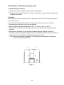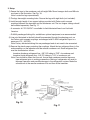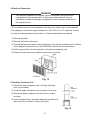
1
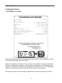
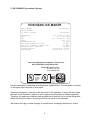
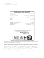
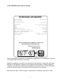
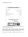
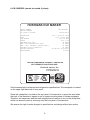
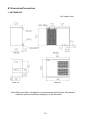
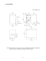
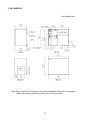
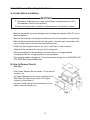
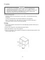
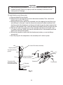
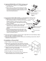
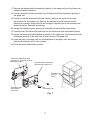
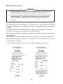
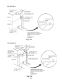
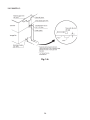
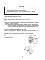
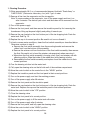
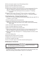
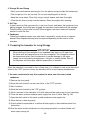
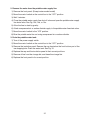
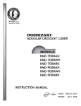
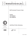
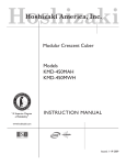
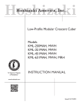
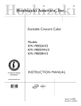
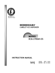
Hoshizaki
Hoshizaki America, Inc.
Stackable Crescent Cuber
Models
KM-1800SAH/3
KM-1800SWH/3
KM-1800SRH/3
“A Superior Degree
of Reliability”
INSTRUCTION MANUAL
www.hoshizaki.com
™
Issued: 10-2-2000
Revised: 12-11-2006
IMPORTANT
Only qualified service technicians should attempt to install, service or maintain
this icemaker. No installation, service or maintenance should be undertaken
until the technician has thoroughly read this Instruction Manual. Likewise, the
owner/manager should not proceed to operate the icemaker until the installer
has instructed them on its proper operation.
HOSHIZAKI provides this manual primarily to assist qualified service technicians in the
installation, maintenance and service of the icemaker.
Should the reader have any questions or concerns which have not been satisfactorily
addressed, please call, write or send an e-mail message to the HOSHIZAKI Technical
Support Department for assistance.
HOSHIZAKI AMERICA, INC.
618 Highway 74 South
Peachtree City, GA 30269
Attn: HOSHIZAKI Technical Support Department
Phone: 1-800-233-1940 Technical Service
(770) 487-2331
Fax: 1-800-843-1056
(770) 487-3360
E-mail: [email protected]
Web Site: www.hoshizaki.com
NOTE: To expedite assistance, all correspondence/communication MUST include the following information:
• Model Number
• Serial Number
• Complete and detailed explanation of the problem
• Please review this manual. It should be read carefully before the icemaker is installed
and operated. Only qualified service technicians should install, service and maintain the
icemaker. This manual should be made available to the technician prior to installation,
maintenance or service.
• Keep this manual with the icemaker for later reference.
CONTENTS
I. Specifications....................................................................................................................... 4
A. Nameplate Rating.......................................................................................................... 4
1. KM-1800SAH (air-cooled)........................................................................................ 4
2. KM-1800SAH3 (air-cooled, 3 phase)........................................................................ 5
3. KM-1800SWH (water-cooled)................................................................................... 6
4. KM-1800SWH3 (water-cooled, 3 phase).................................................................. 7
5. KM-1800SRH (remote air-cooled)............................................................................ 8
6. KM-1800SRH3 (remote air-cooled, 3 phase)........................................................... 9
B. Dimensions/Connections............................................................................................. 10
1. KM-1800SAH/3....................................................................................................... 10
2. KM-1800SWH/3...................................................................................................... 11
3. KM-1800SRH/3...................................................................................................... 12
II. Installation and Operating Instructions............................................................................. 13
A. Checks Before Installation........................................................................................... 13
B. How to Remove Panels................................................................................................ 13
C. Location....................................................................................................................... 14
D. Setup............................................................................................................................ 14
E. Installation of Second Unit........................................................................................... 16
F. Electrical Connection.................................................................................................... 18
G. Installation of Remote Condenser Unit........................................................................ 19
1. Checks Before Installation...................................................................................... 19
2. Location.................................................................................................................. 19
3. Setup...................................................................................................................... 20
4. Electrical Connection.............................................................................................. 21
5. Stacking Condenser Unit........................................................................................ 21
H. Water Supply and Drain Connections.......................................................................... 22
I. Final Checklist .............................................................................................................. 25
J. Startup.......................................................................................................................... 26
III. Cleaning and Maintenance Instructions.......................................................................... 27
A. Cleaning Instructions................................................................................................... 27
1. Cleaning Procedure................................................................................................ 28
2. Sanitizing Procedure - Following Cleaning Procedure........................................... 29
I. Specifications
A. Nameplate Rating
1. KM-1800SAH (air-cooled)
HOSHIZAKI ICE MAKER
MODEL NUMBER
SERIAL NUMBER
AC SUPPLY VOLTAGE
KM-1800SAH
208-230/60/1 (3 WIRE WITH
NEUTRAL FOR 115V)
COMPRESSOR
230V 13RLA 82LRA
PUMP
120V 1.2FLA 60W
FAN
115V 2FLA(total) 60W
OTHER
115V 0.3A
MAXIMUM FUSE SIZE
30 AMPS
MAX. HACR BREAKER(USA ONLY)
30 AMPS
MAX. CIRC. BREAKER (CANADA ONLY)
30 AMPS
MINIMUM CIRCUIT AMPACITY
30 AMPS
DESIGN PRESSURE
HI-467PSI LO-230PSI
REFRIGERANT
R-404A 4LBS. 6.5oz.
MOTOR-COMPRESSOR THERMALLY PROTECTED,
NOT INTENDED FOR OUTDOOR USE!
Hoshizaki America, Inc.
Peachtree City, GA
www.hoshizaki.com
LISTED
ICE MAKER
WITHOUT
STORAGE
MEANS
946Z
See the nameplate for electrical and refrigeration specifications. This nameplate is located
on the upper right hand side of rear panel.
Since this nameplate is located on the rear panel of the icemaker, it cannot be read when
the back of the icemaker is against a wall or against another piece of kitchen equipment.
Therefore, the necessary electrical and refrigeration information is also on the rating label,
which can be easily seen by removing only the front panel of the icemaker.
We reserve the right to make changes in specifications and design without prior notice.
2. KM-1800SAH3 (air-cooled, 3 phase)
HOSHIZAKI ICE MAKER
MODEL NUMBER
SERIAL NUMBER
AC SUPPLY VOLTAGE
KM-1800SAH3
208-230/60/3
COMPRESSOR
PUMP
FAN
OTHER
MAXIMUM FUSE SIZE
MAX. HACR BREAKER(USA ONLY)
MAX. CIRC. BREAKER (CANADA ONLY)
MINIMUM CIRCUIT AMPACITY
DESIGN PRESSURE
REFRIGERANT
230V 7.5RLA 65.5LRA
120V 1.2FLA 60W
115V 2FLA(total) 60W
115V 0.3A
20 AMPS
20 AMPS
20 AMPS
20 AMPS
HI-467PSI LO-230PSI
R-404A 4LBS. 6.5oz.
MOTOR-COMPRESSOR THERMALLY PROTECTED,
NOT INTENDED FOR OUTDOOR USE!
Hoshizaki America, Inc.
Peachtree City, GA
www.hoshizaki.com
LISTED
ICE MAKER
WITHOUT
STORAGE
MEANS
946Z
See the nameplate for electrical and refrigeration specifications. This nameplate is located
on the upper right hand side of rear panel.
Since this nameplate is located on the rear panel of the icemaker, it cannot be read when
the back of the icemaker is against a wall or against another piece of kitchen equipment.
Therefore, the necessary electrical and refrigeration information is also on the rating label,
which can be easily seen by removing only the front panel of the icemaker.
We reserve the right to make changes in specifications and design without prior notice.
3. KM-1800SWH (water-cooled)
HOSHIZAKI ICE MAKER
MODEL NUMBER
SERIAL NUMBER
AC SUPPLY VOLTAGE
KM-1800SWH
208-230/60/1 (3 WIRE WITH
NEUTRAL FOR 115V)
COMPRESSOR
230V 10.9RLA 82LRA
PUMP
120V 1.2FLA 60W
FAN
- - OTHER
115V 0.3A
MAXIMUM FUSE SIZE
30 AMPS
MAX. HACR BREAKER(USA ONLY)
30 AMPS
MAX. CIRC. BREAKER (CANADA ONLY)
30 AMPS
MINIMUM CIRCUIT AMPACITY
30 AMPS
DESIGN PRESSURE
HI-427PSI LO-230PSI
REFRIGERANT
R-404A 3LBS. 2oz.
MOTOR-COMPRESSOR THERMALLY PROTECTED,
NOT INTENDED FOR OUTDOOR USE!
Hoshizaki America, Inc.
Peachtree City, GA
www.hoshizaki.com
LISTED
ICE MAKER
WITHOUT
STORAGE
MEANS
946Z
See the nameplate for electrical and refrigeration specifications. This nameplate is located
on the upper right hand side of rear panel.
Since this nameplate is located on the rear panel of the icemaker, it cannot be read when
the back of the icemaker is against a wall or against another piece of kitchen equipment.
Therefore, the necessary electrical and refrigeration information is also on the rating label,
which can be easily seen by removing only the front panel of the icemaker.
We reserve the right to make changes in specifications and design without prior notice.
4. KM-1800SWH3 (water-cooled, 3 phase)
HOSHIZAKI ICE MAKER
MODEL NUMBER
SERIAL NUMBER
AC SUPPLY VOLTAGE
KM-1800SWH3
208-230/60/3
COMPRESSOR
PUMP
FAN
OTHER
MAXIMUM FUSE SIZE
MAX. HACR BREAKER(USA ONLY)
MAX. CIRC. BREAKER (CANADA ONLY)
MINIMUM CIRCUIT AMPACITY
DESIGN PRESSURE
REFRIGERANT
230V 8.2RLA 65.5LRA
120V 1.2FLA 60W
- - 115V 0.3A
20 AMPS
20 AMPS
20 AMPS
20 AMPS
HI-427PSI LO-230PSI
R-404A 3LBS. 2oz.
MOTOR-COMPRESSOR THERMALLY PROTECTED,
NOT INTENDED FOR OUTDOOR USE!
Hoshizaki America, Inc.
Peachtree City, GA
www.hoshizaki.com
LISTED
ICE MAKER
WITHOUT
STORAGE
MEANS
946Z
See the nameplate for electrical and refrigeration specifications. This nameplate is located
on the upper right hand side of rear panel.
Since this nameplate is located on the rear panel of the icemaker, it cannot be read when
the back of the icemaker is against a wall or against another piece of kitchen equipment.
Therefore, the necessary electrical and refrigeration information is also on the rating label,
which can be easily seen by removing only the front panel of the icemaker.
We reserve the right to make changes in specifications and design without prior notice.
5. KM-1800SRH (remote air-cooled)
HOSHIZAKI ICE MAKER
MODEL NUMBER
SERIAL NUMBER
AC SUPPLY VOLTAGE
KM-1800SRH
208-230/60/1 (3 WIRE WITH
NEUTRAL FOR 115V)
COMPRESSOR
230V 10.9RLA 82LRA
PUMP
120V 1.2FLA 60W
FAN REMOTE
120V 3A MAX
OTHER
115V 0.3A
MAXIMUM FUSE SIZE
30 AMPS
MAX. HACR BREAKER(USA ONLY)
30 AMPS
MAX. CIRC. BREAKER (CANADA ONLY)
30 AMPS
MINIMUM CIRCUIT AMPACITY
30 AMPS
DESIGN PRESSURE
HI-467PSI LO-230PSI
REFRIGERANT
R-404A
MOTOR-COMPRESSOR THERMALLY PROTECTED,
NOT INTENDED FOR OUTDOOR USE!
Hoshizaki America, Inc.
Peachtree City, GA
www.hoshizaki.com
LISTED
ICE MAKER
WITHOUT
STORAGE
MEANS
946Z
See the nameplate for electrical and refrigeration specifications. This nameplate is located
on the upper right hand side of rear panel.
Since this nameplate is located on the rear panel of the icemaker, it cannot be read when
the back of the icemaker is against a wall or against another piece of kitchen equipment.
Therefore, the necessary electrical and refrigeration information is also on the rating label,
which can be easily seen by removing only the front panel of the icemaker.
We reserve the right to make changes in specifications and design without prior notice.
6. KM-1800SRH3 (remote air-cooled, 3 phase)
HOSHIZAKI ICE MAKER
MODEL NUMBER
SERIAL NUMBER
AC SUPPLY VOLTAGE
KM-1800SRH3
208-230/60/3
COMPRESSOR
PUMP
FAN REMOTE
OTHER
MAXIMUM FUSE SIZE
MAX. HACR BREAKER(USA ONLY)
MAX. CIRC. BREAKER (CANADA ONLY)
MINIMUM CIRCUIT AMPACITY
DESIGN PRESSURE
REFRIGERANT
230V 7.5RLA 65.5LRA
120V 1.2FLA 60W
120V 3A MAX
115V 0.3A
20 AMPS
20 AMPS
20 AMPS
20 AMPS
HI-467PSI LO-230PSI
R-404A
MOTOR-COMPRESSOR THERMALLY PROTECTED,
NOT INTENDED FOR OUTDOOR USE!
Hoshizaki America, Inc.
Peachtree City, GA
www.hoshizaki.com
LISTED
ICE MAKER
WITHOUT
STORAGE
MEANS
946Z
See the nameplate for electrical and refrigeration specifications. This nameplate is located
on the upper right hand side of rear panel.
Since this nameplate is located on the rear panel of the icemaker, it cannot be read when
the back of the icemaker is against a wall or against another piece of kitchen equipment.
Therefore, the necessary electrical and refrigeration information is also on the rating label,
which can be easily seen by removing only the front panel of the icemaker.
We reserve the right to make changes in specifications and design without prior notice.
B. Dimensions/Connections
1. KM-1800SAH/3
Unit: inches (mm)
Note: When used with a storage bin not recommended by Hoshizaki, the icemaker
needs the space at the bottom opening as in the illustration.
10
2. KM-1800SWH/3
Unit: inches (mm)
Note: When used with a storage bin not recommended by Hoshizaki, the icemaker
needs the space at the bottom opening as in the illustration.
11
3. KM-1800SRH/3
Unit: inches (mm)
Note: When used with a storage bin not recommended by Hoshizaki, the icemaker
needs the space at the bottom opening as in the illustration.
12
II. Installation and Operating Instructions
A. Checks Before Installation
IMPORTANT
1. Remove all shipping cartons, tape and packing. If packing material is left in
the icemaker, it will not work properly.
2. Ensure all components, fasteners and thumbscrews are securely in place.
• Remove the panels to prevent damage when installing the icemaker. (See "B. How to
Remove Panels.")
• Remove the package containing the accessories from the compressor compartment.
• Remove the protective plastic film from the panels. If the icemaker is exposed to the
sun or to heat, remove the film after the icemaker cools.
• Check that the refrigerant lines do not rub or touch lines or other surfaces.
• Check that the compressor is snug on all mounting pads.
• See the nameplate on the rear panel, and check that your voltage supplied
corresponds with the voltage specified on the nameplate.
• This icemaker needs a storage bin. The recommended storage bin is HOSHIZAKI ICE
STORAGE BIN, Model B-800 series.
B. How to Remove Panels
See Fig. 1
• Front Panel: Remove the two screws. Lift up and pull
towards you.
• Top Panel: Remove the two screws, and then lift off.
• Side Panel (R): Remove the screw. Pull slightly
towards you, and take off.
• Insulation Panel: Remove the thumbscrew. Lift up
slightly, and pull towards you.
Fig. 1
13
C. Location
WARNING
This icemaker is not intended for outdoor use. Normal operating ambient
temperature should be within +45°F to +100°F (+7°C to +38°C); Normal
operating water temperature should be within +45°F to +90°F (+7°C to +32°C).
Operation of the icemaker, for extended periods, outside of these normal
temperature ranges may affect production capacity.
For best operating results:
• Icemaker should not be located next to ovens, grills or other high heat producing
equipment.
• Location should provide a firm and level foundation for the equipment.
• Allow 12" clearance at rear, sides and top for proper air circulation and ease of
maintenance and/or service should they be required.
D. Setup
1) Unpack the storage bin, and attach the four adjustable legs provided to the bottom of
the storage bin.
2) Position the storage bin in the selected permanent location.
3) Place the icemaker on top of the storage bin.
4) Secure the icemaker to the storage bin by using the two universal braces and two of the
bolts provided. See Fig. 2.
Fig. 2
14
CAUTION
Before operating the icemaker, the bin control thermostat assembly must be
installed correctly. Failure to properly install the assembly could result in ice
backup and unit damage.
5) Install the bin control thermostat.
a. Remove the baffle from the bin.
b. Remove the tie securing the bin control thermostat assembly. Then, remove the
thumbscrew and the "Z" bracket.
c. Remove the bin control thermostat assembly from the shipping hook by lifting it up
and shifting it to the right. Lower the thermostat extension bracket (stainless) with
the thermostat bulb attachment and thermostat bulb through the hole located at the
bottom of the icemaker. Next, lower the thermostat bracket (plastic) through the hole.
d. Slide the left side of the upper part of the assembly towards you and make sure it
is hooked on the wall. Make sure the left side and bottom of the assembly are flush
against the wall and base panel.
e. Secure the assembly in place with the thumbscrew (unless you are installing a
second unit).
f. Insert the plug into the receptacle on the assembly until it locks in place.
Bin Control Thermostat Assembly
Wall
Shipping Hook
Thermostat Bracket
(plastic)
Plug
Hook
Bushing
Tie
Thermostat Bulb
Attachment (plastic)
and Thermostat Bulb
Thermostat Extension
Bracket (stainless)
Receptacle
"Z" Bracket
Thumbscrew
Hole
Fig. 3
15
Thumbscrew
If a Hoshizaki B-800, B-900 or B-1150 bin is being used:
g. Put aside the "Z" bracket; it is not needed with the
bins listed above.
h. Remove the two screws from the lower part of the
thermostat bracket (plastic) and use them to attach
the thermostat extension bracket (stainless) to the
thermostat bracket (plastic).
Thermostat Bracket
(plastic)
Thermostat Extension
Bracket (stainless)
Fig. 4
If a Hoshizaki B-1300, B-1500, B-1650 or non-Hoshizaki bin is being used:
g. Remove the two screws securing the thermostat
Thermostat Bracket
bulb attachment (plastic) to the thermostat extension (plastic)
bracket (stainless). Use the two screws to attach
the "Z" bracket (plastic) to the thermostat extension
Thermostat Bulb
bracket (stainless).
Attachment (plastic)
h. Use the two 4×10 stainless steel screws in the
accessory bag to attach the thermostat bulb
Thermostat Extension
attachment (with attached thermostat bulb) to the "Z"
Bracket (stainless)
bracket.
i. Remove the two screws from the lower part of the
"Z" Bracket (plastic)
thermostat bracket (plastic) and use them to attach
the thermostat extension bracket (stainless) to the
Fig. 5
thermostat bracket (plastic).
6) Level the icemaker/storage bin in both the left-to-right and front-to-rear directions. Adjust
the ice bin legs to make the icemaker level.
7) Place the panels and baffle in position (unless you are installing a second unit). (See "E.
Installation of Second Unit.")
E. Installation of Second Unit
1) See "D. Setup" for the lower unit installation.
2) Remove the top panel and the top insulation of the lower
unit. The top panel and the top insulation of the lower unit
Universal
are not required when installing the second icemaker.
3) Unpack the second icemaker (upper unit), and remove all
shipping cartons, tape and packing.
4) Remove the panels of the second icemaker.
5) Stack the upper unit on top of the lower unit.
6) Secure the upper unit to the lower unit by using the two
universal braces and the four bolts provided.
16
Brace
Icemaker
(Upper
Unit)
Bolt
Icemaker
(Lower
Unit)
Bin
Fig. 6
7) Remove the thermostat bulb attachment (plastic) of the upper unit from the thermostat
extension bracket (stainless).
8) Carefully remove the thermostat bulb from the thermostat bulb attachment (plastic) of
the upper unit.
9) Carefully route the thermostat bulb and capillary tubing of the upper unit through
the bottom hole of the upper unit. Remove the bushing from the lower bin control
thermostat assembly. Route the bulb and tubing through the hole in the assembly and
down into the bin. Reattach the bushing.
10) Secure the lower bin control thermostat assembly in place with the thumbscrew.
11) Carefully insert the thermostat bulb back into the thermostat bulb attachment (plastic).
12) Secure the thermostat bulb attachment (plastic) of the upper unit to the thermostat bulb
attachment (plastic) of the lower unit with the screws of the upper unit.
13) Insert the plug of the upper unit into the receptacle of the upper unit's bin control
thermostat assembly until it locks in place.
14) Place the panels and baffle in position.
Thermostat Extension Bracket
(stainless) or "Z" Bracket (plastic)
Depending on Bin
Thermostat Bulb Attachment
Removed from Upper Unit
Thermostat
Capillary
Tubing
Thermostat Bulb
Attachment of
Lower Unit
Thermostat Bulb
Fig. 7
17
F. Electrical Connection
WARNING
1. Electrical connection must be made in accordance with the instructions on a
"WARNING" tag, provided with the pig tail leads in the junction box.
2. This icemaker requires a ground that meets the national and local electrical
code requirements. To prevent possible electrical shock to individuals or
extensive damage to the equipment, install a proper ground wire to the
icemaker.
• On single phase models (KM-1800S_H), the white lead must be connected to the neutral
conductor of the power source. Miswiring results in severe damage to the icemaker. See
Fig. 8a.
• On three phase models (KM-1800S_H3), the voltage tap switch in the unit should be
positioned to match incoming voltage at start-up. See Fig. 8b.
• This icemaker must have a separate power supply or receptacle of proper capacity. See
the nameplate.
• The opening for the power supply connection is 7/8" DIA to fit a 1/2" trade size conduit.
• When excessive voltage is supplied to the controller board, the icemaker stops running in
3 seconds. See "J. Startup."
• Usually an electrical permit and services of a licensed electrician are required.
KM-1800S_H
KM-1800S_H3
Fig. 8a
Fig. 8b
18
G. Installation of Remote Condenser Unit
1. Checks Before Installation
1) Unpack and remove shipping carton, tape(s) and packing.
2) Check that the refrigerant lines do not rub or touch lines or other surfaces, and that the
fan blade turns freely.
2. Location
The condenser unit must be positioned in a permanent site under the following guidelines.
• A firm and flat site.
• A dry and well ventilated area with 24" clearance on both front and rear for ease of
maintenance and service should they be required.
• Normal condenser ambient temperature: -20°F to +122°F (-29°C to +50°C).
Temperatures not within this operating range may affect the production capacity of the
icemaker.
• The maximum line length for the standard refrigerant charge is 66 feet. Should an
installation require a longer line length, please call 1-800-233-1940 for recommendations
concerning the correct additional refrigerant charge to be added.
Note: If the recommended guidelines of the installation are exceeded, the icemaker
performance may be reduced.
Air
Fig. 9
19
Air
3. Setup
1) Secure the legs to the condenser unit with eight M8×16 mm hexagon bolts and M8 nuts
as shown in the illustration. See Fig. 10.
Note: Locate the legs symmetrically.
2) The legs have eight mounting holes. Secure the legs with eight bolts (not included).
3) Install enough length of two copper tubings provided with Parker quick connect
couplings between the icemaker and the condenser unit. The two copper tubings should
be insulated separately. See Fig. 11.
• A connector kit "OS-QUICK" is available for field-fabricated lines from Hoshizaki
America.
• R-404A precharged tubing kits, available as optional equipment, are recommended.
4) Line sets fabricated in the field should be evacuated through the charging ports on
the Parker quick connect couplings and charged with R-404A refrigerant vapor to a
pressure of 15 - 30 PSIG.
Note: Factory fabricated tubing kits are precharged and do not need to be evacuated.
5) Remove the plastic caps protecting the couplings. Attach the two refrigerant lines to the
male couplings on the icemaker and the remote condenser unit. Each refrigerant line
must be connected as follows:
Icemaker discharge refrigerant line - 5/8" OD tubing to "DIS" of condenser unit
Icemaker liquid refrigerant line - 3/8" OD tubing to "LIQ" of condenser unit
Note: Care should be taken that the unit, line set and condenser contain the same
type refrigerant prior to making connections. Mixing of refrigerants will result in
improper operation and possible damage to the refrigeration system. Make the
connections at the remote condenser first and then at the icemaker.
Fig. 10
Fig. 11
20
4. Electrical Connection
WARNING
This remote condenser unit requires a ground that meets the national and
local electrical code requirements. To prevent possible electrical shock to
individuals or extensive damage to equipment, install a proper ground wire to
this condenser unit.
• This condenser unit must be connected to the fan motor junction box on the icemaker.
• The opening for the power supply connection is 7/8" DIA to fit a 1/2" trade size conduit.
• Usually an electrical permit and services of a licensed electrician are required.
1) Remove the panel.
2) Remove the junction box cover.
3) Connect the fan motor leads in the junction box of the remote condenser unit to the fan
motor leads in the junction box of the HOSHIZAKI remote air-cooled icemaker.
4) Install a ground wire from the icemaker to the remote condenser unit.
5) Place the junction box cover and the louver panel in position.
Fig. 12
5. Stacking Condenser Unit
1) Secure the lower condenser unit to the legs with eight
bolts (not included).
2) Attach the upper condenser unit on the top of the lower.
3) Secure the upper condenser unit with the four screws
provided.
4) Install refrigerant lines, and make electrical connection for
each fan motor as shown in Items [c] and [d].
Fig. 13
21
H. Water Supply and Drain Connections
See Fig. 14a, 14b and 14c
WARNING
To prevent damage to the pump assembly, do not operate the icemaker when
the water supply is OFF, or if the pressure is below 10 PSIG. Do not run the
icemaker until the proper water pressure is reached.
• Water supply inlet is 1/2" female pipe thread (FPT).
Note: On water-cooled model, two water supply inlets are provided. One is for the
icemaker, and the other is for the water-cooled condenser.
• A water supply line shut-off valve and drain valve should be installed. A minimum of 1/2"
OD copper tubing is recommended for the water supply lines.
• Water supply pressure should be a minimum of 10 PSIG and a maximum of 113 PSIG. If
the pressure exceeds 113 PSIG, the use of a pressure reducing valve is required.
• Drain outlet for icemaker dump is 3/4" FPT. The drain for condensation is a 3/8" ID
pipe. The icemaker drain and the condenser drain piping connections must be made
separately from the bin drain.
Note: On water-cooled model, a 1/2" FPT is provided for the condenser drain outlet.
• The drains must have 1/4" fall per foot on horizontal runs to get a good flow.
• The drains should not be piped directly to the sewer system. An air gap of a minimum of 2
vertical inches should be between the end of the drain pipe from the icemaker or the ice
bin and the floor drain.
• This icemaker should be installed in accordance with applicable national, state and local
regulations.
• A plumbing permit and services of a licensed plumber may be required in some areas.
• In some areas, a back flow preventer may be required in the cooling water circuit.
22
KM-1800SAH/3
Fig. 14a
KM-1800SWH/3
Fig. 14b
23
KM-1800SRH/3
Fig. 14c
24
I. Final Checklist
1) Is the icemaker level?
2) Is the icemaker in a site where the ambient temperature is within +45°F to +100°F
(+7°C to +38°C) all year around?
3) Is there at least a 12" clearance around the icemaker for maintenance or service?
4) Have all shipping tape(s), packing and cartons been removed from the icemaker? Are
the cube guides in their correct position? Are the separators properly attached to their
holding clips?
5) Are all components, fasteners and thumbscrews securely in place?
6) Have all electrical and piping connections been made?
7) Has the power supply voltage been checked or tested against the nameplate rating?
Has the voltage tap switch in the three phase model unit been positioned to match
incoming voltage? Has a proper ground been installed in the icemaker?
8) Are the water supply line shut-off valve and drain valve installed? Has the water
supply pressure been checked to ensure a minimum of 10 PSIG and a maximum of
113 PSIG?
Note: The icemaker may stop running when the water supply is OFF, or if the pressure
is below 10 PSIG. When the proper water pressure is reached, the icemaker
automatically starts running again.
9) Have the compressor hold-down bolts and refrigerant lines been checked against
vibration and possible failure?
10) Has the bin control switch been checked for correct operation? When the icemaker is
running, hold an ice cube in contact with the bulb. The icemaker should stop within 6 to
10 seconds.
11) Has the end user been given the instruction manual, and instructed on how to operate
the icemaker and the importance of the recommended periodic maintenance?
12) Has the end user been given the name and telephone number of an authorized service
agent?
13) Has the warranty tag been filled out and forwarded to the factory for warranty
registration?
25
J. Startup
CAUTION
1. All parts are factory-adjusted. Improper adjustments may result in failure.
2. If the unit is turned off, wait for at least 3 minutes before restarting the
icemaker to prevent damage to the compressor.
3. Do not operate the unit in the "WASH" position without water in the water
tank. This will cause damage to the water pump seal.
1) Open the water supply line shut-off valve.
2) Remove the front panel.
3) Move the control switch on the control box to the "ICE" position.
4) Replace the front panel in its correct position.
5) Turn on the power supply, and allow the water tank to fill with water and the icemaker to
operate for a total of 10 minutes.
Note: If miswiring causes excessive voltage on the controller board, the high voltage
cut-out shuts down the circuit in 3 seconds and the icemaker automatically stops.
When the proper supply voltage is resumed, the icemaker automatically starts
running again.
6) Turn off the power supply, and remove the front panel.
7) Remove the insulation panel. Remove the cap located on the front bottom part of the
ice dropping hole. Drain the water tank. See Fig. 15.
8) Replace the cap, insulation panel and front panel in their correct position.
9) Clean the storage bin.
10) Turn on the power supply, and start the automatic
icemaking process.
Fig. 15
26
III. Cleaning and Maintenance Instructions
IMPORTANT
Ensure all components, fasteners and thumbscrews are securely in place after
any maintenance or cleaning is done to the equipment.
A. Cleaning Instructions
WARNING
1. HOSHIZAKI recommends cleaning this unit at least once a year. More
frequent cleaning, however, may be required in some existing water
conditions.
2. To prevent injury to individuals and damage to the icemaker, do not use
ammonia type cleaners.
3. Always wear liquid-proof gloves to prevent the cleaning and sanitizing
solutions from coming into contact with skin.
IMPORTANT
1. The cleaning valve is used to provide access to the inside of the evaporator
during the cleaning and sanitizing operation. It should be closed for all
icemaking operation. The compressor will not operate unless this valve is
completely closed.
2. To open the cleaning valve, the valve handle should be parallel to the valve
body. To close the valve, the valve handle should be at a right angle to the
valve body.
CLOSED POSITION 27
OPEN POSITION
1. Cleaning Procedure
1) Dilute approximately 38 fl. oz. of recommended cleaner Hoshizaki "Scale Away" or
"LIME-A-WAY," (Economics Laboratory, Inc.) with 7 gal. of water.
2) Remove all ice from the evaporator and the storage bin.
Note: To remove cubes on the evaporator, turn off the power supply and turn it on
after 3 minutes. The defrost cycle starts and the cubes will be removed from the
evaporator.
3) Turn off the power supply.
4) Remove the front panel, and then remove the insulation panel by first removing the
thumbscrew, lifting up the panel slightly and pulling it towards you.
5) Remove the cap located on the front bottom part of the ice dropping hole. Drain the
water tank. See Fig. 15.
6) Replace the cap in its correct position. Be careful not to cross thread it.
7) In bad or severe water conditions, clean the float switch assembly as described below.
Otherwise, continue to step 8.
a. Remove the float switch assembly from the mounting bracket and remove the
rubber boot from the bottom of the assembly.
b. Remove the retainer rod from the bottom of the float switch assembly, then remove
the float. Be careful not to bend the retainer rod excessively when removing it.
c. Wipe down the float switch assembly's housing, shaft, float, and retainer rod with
cleaning solution. Wipe the inside of the rubber boot with cleaning solution.
d. Reassemble the float switch assembly and replace it and the rubber boot in their
correct positions.
8) Pour the cleaning solution into the water tank.
9) Fully open the cleaning valve on the left side wall of the machine compartment.
10) Move the control switch on the control box to the "WASH" position
11) Replace the insulation panel and the front panel in their correct positions.
12) Turn on the power supply, and start the washing process.
13) Turn off the power supply after 30 minutes.
14) Remove the front panel and the insulation panel.
15) Remove the cap located on the front bottom part of the ice dropping hole. Drain the
water tank. Replace the cap and the insulation panel in their correct positions.
16) Move the control switch to the "ICE" position.
17) Close the cleaning valve.
18) Replace the front panel in its correct position.
19) Turn on the power supply to fill the water tank with water.
20) Turn off the power supply after 3 minutes.
21) Remove the front panel, and fully open the cleaning valve.
22) Move the control switch to the "WASH" position.
23) Replace the front panel in its correct position.
28
24) Turn on the power supply to rinse off the cleaning solution.
25) Turn off the power supply after 5 minutes.
26) Remove the front panel and the insulation panel.
27) Remove the cap located on the front bottom part of the ice dropping hole. Drain the
water tank. Replace the cap and the insulation panel in their correct positions.
Note: Do not replace the insulation panel when you proceed to "2. Sanitizing
Procedure."
28) Repeat the above steps 16 through 27 three more times to rinse thoroughly.
Note: If you do not sanitize the icemaker, go to step 9 in "2. Sanitizing Procedure."
2. Sanitizing Procedure - Following Cleaning Procedure
1) Dilute a 5.25% sodium hypochlorite solution (chlorine bleach) with water (add 3.5 fl. oz.
of sanitizer to 7 gal. of water).
2) Pour the sanitizing solution into the water tank.
3) Replace the insulation panel and the front panel in their correct positions.
Note: Make sure that the control switch is in the "WASH" position and the cleaning
valve is open.
4) Turn on the power supply, and start the sanitizing process.
5) Turn off the power supply after 15 minutes.
6) Remove the front panel and the insulation panel.
7) Remove the cap located on the front bottom part of the ice dropping hole. Drain the
water tank. Replace the cap and the insulation panel in their correct positions.
8) Repeat the above steps 16 through 27 in "1. Cleaning Procedure" two times to rinse
thoroughly.
9) Close the cleaning valve.
10) Move the control switch to the "ICE" position.
11) Replace the front panel in its correct position.
12) Clean the storage bin with water.
13) Turn on the power supply, and start the automatic icemaking process.
B. Maintenance Instructions
IMPORTANT
This icemaker must be maintained individually, referring to the instruction
manual and labels provided with the icemaker.
1. Stainless Steel Exterior
To prevent corrosion, wipe the exterior occasionally with a clean and soft cloth. Use a
damp cloth containing a neutral cleaner to wipe off oil or dirt build up.
29
2. Storage Bin and Scoop
• Wash your hands before removing ice. Use the plastic scoop provided (bin accessory).
• The storage bin is for ice use only. Do not store anything else in the bin.
• Keep the scoop clean. Clean it by using a neutral cleaner and rinse thoroughly.
• Clean the bin liner by using a neutral cleaner. Rinse thoroughly after cleaning.
3. Air Filter
A plastic mesh air filter removes dirt or dust from the air, and keeps the condenser from
getting clogged. As the filter gets clogged, the icemaker’s performance will be reduced.
Check the filter at least twice a month. When clogged, use warm water and a neutral
cleaner to wash the filter.
4. Condenser
Check the condenser once a year, and clean if required by using a brush or vacuum
cleaner. More frequent cleaning may be required depending on the location of the
icemaker.
C. Preparing the Icemaker for Long Storage
IMPORTANT
When shutting off the icemaker for an extended time, drain out all water from
the water tank and remove the ice from the storage bin. The storage bin should
be cleaned and dried. Drain the icemaker to prevent damage to the water
supply line at sub-freezing temperatures, using air or carbon dioxide. Shut off
the icemaker until the proper ambient temperature is resumed.
When the icemaker is not used for two or three days, it is sufficient to only move the control
switch to the "OFF" position, unless the icemaker will be at sub-freezing temperatures.
1. On water-cooled model only, first remove the water from the water-cooled
condenser:
1) Remove the front panel.
2) Move the control switch, on the control box, to the "OFF" position.
3) Wait 3 minutes.
4) Move the control switch to the "ICE" position.
5) Allow 5 minutes for the icemaker to fill with water and the water pump to start operating.
6) Close the water-cooled condenser water supply line shut-off valve. See Fig. 14b.
7) Open the drain valve for the water-cooled condenser water supply line.
8) Allow the line to drain by gravity.
9) Quickly attach compressed air or carbon dioxide supply to the condenser water line
drain valve.
10) Blow the water-cooled condenser out using compressed air or carbon dioxide until
water stops coming out.
30
2. Remove the water from the potable water supply line:
1) Remove the front panel. (Except water-cooled model)
2) Move the control switch on the control box to the "OFF" position.
3) Wait 3 minutes.
4) Close the potable water supply line shut-off valve and open the potable water supply
line drain valve. See Fig. 14a, 14b, or 14c.
5) Allow the line to drain by gravity.
6) Attach compressed air or carbon dioxide supply to the potable water line drain valve.
7) Move the control switch to the "ICE" position.
8) Blow the potable water line out using compressed air or carbon dioxide.
3. Drain the potable water tank:
1) Turn off the power supply switch.
2) Move the control switch on the control box to the "OFF" position.
3) Remove the insulation panel. Remove the cap located on the front bottom part of the
ice dropping hole. Drain the water tank. See Fig. 15.
4) Replace the cap and the insulation panel in their correct positions.
5) Remove all ice from the storage bin, and clean the storage bin.
6) Replace the front panel in its correct position.
31
HOSHIZAKI AMERICA, INC.
618 Hwy. 74 S., Peachtree City, GA 30269 USA TEL (770) 487-2331 FAX (770) 487-3360 www.hoshizaki.com 91A1SA10D
32