1
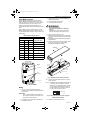
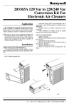
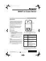
69-1200-2.fm Page 1 Tuesday, December 3, 2002 11:21 AM
W8600F Air Cleaner Monitor
INSTALLATION INSTRUCTIONS
APPLICATION
LCD
The W8600F Air Cleaner Monitor is an option available
for use with the F50F and F52F Honeywell Electronic Air
Cleaners (EAC). The series two F50F and F52F require
a solid state power supply that is compatible with the
W8600F driver board. Any series one F50E, F or F52F
can be upgraded to use the W8600F when the power
supply is replaced and the driver board (included in
W8600F kit) is installed.
ON
BATTERY
SERVICE
FAULT
Air Cleaner Monitor
FUNCTION
INDICATOR
PANEL
The W8600F function indicator panel has four liquid
crystal display (LCD) arrowheads that point to ON,
BATTERY, SERVICE or FAULT. See Fig. 1. The
arrowheads darken to indicate the existing EAC
condition. See Table 1.
INSTALLATION
RESET BUTTON
M11965
When Installing this Product..
1.
2.
3.
4.
Fig. 1. W8600F Air Cleaner Monitor features.
Read these instructions carefully. Failure to follow
the instructions could damage the product or cause
a hazardous condition.
Check the ratings given in the instructions and on
the product to make sure the product is suitable for
your application
Installer must be a trained, experienced service
technician.
After completing the installation, use these instructions to check out the product operation.
Table 1. Description of W8600F Function Indicator
Panel.
Indicators
ON
EAC is powered and system blower is
running.
BATTERY
Battery that maintains W8600F
memory is low and needs to be
replaced.
SERVICE
EAC prefilter and cells need to be
washeda.
FAULT
•Shorting of collector plates.
•Continuous ionizer or collector plate
arcing.
•Power supply failure.
•Excessive current.
•Major reduction in high voltage.
•EAC prefilter and cells are past
SERVICE level of dirt and need to be
washed immediately.
Call a service technician.
Location
The styling of the W8600F is designed to blend with the
latest T8600 family of Honeywell Chronotherm¨ IV
Deluxe Programmable Thermostats. A special mounting
template is included for mounting next to the T8600. The
W8600F can also be mounted at any other convenient
location in the living area or equipment room. See Fig. 2.
NOTE: The W8600F shares no common electrical connections with the thermostat.
a
® U.S. Registered Trademark
Copyright © 2002 Honeywell International Inc. •
Condition
The reset button is located on the bottom of W8600F.
After the prefilters and cells are cleaned and reinstalled,
press this button to turn off the SERVICE indicator and
reset the wash frequency timer.
• All Rights Reserved
69-1200-2
69-1200-2.fm Page 2 Tuesday, December 3, 2002 11:21 AM
W8600F AIR CLEANER MONITOR
EAC
W8600F
On
Battery
Service
Fault
W8600F
Air Clea
ner Mon
itor
EAC
RETURN AIR DUCT
CEMENT BLOCK WALL
EAC
W8600F
W8600F
EAC
W8600F
EAC
CLOSET
GARAGE/DRYWALL
F52-ATTIC
M11966
Fig. 2. W8600F mounting locations.
Mounting
The following mounting instructions assume that the
W8600F is mounted next to a T8600 Thermostat. If
installing the monitor at another location, modify the
procedure to fit the installation.
1.
2.
3.
4.
5.
THERMOSTAT
WALLPLATE
Hold the mounting template (included in the
W8600F kit) next to the T8600 as shown in Fig. 3.
Mark the holes for the screw anchors and the
3-conductor thermostat cable.
Remove the template and drill the holes.
Remove the W8600F from the base.
Position the W8600F base over the holes and
install the anchors and screws (included in the bag
assembly). Tighten the screws until the base is
mounted firmly on the wall.
69-1200—2
MOUNTING
TEMPLATE
WIRING HOLE
MOUNTING HOLES (2)
Fig. 3. Positioning mounting template.
2
M11971
69-1200-2.fm Page 3 Tuesday, December 3, 2002 11:21 AM
W8600F AIR CLEANER MONITOR
Select Wash Frequency
3.
Use the W8600F DIP switches to program the time
between SERVICE indications. Be sure to select the
setting according to the conditions of the home. Factors
to consider include the duty cycle of the EAC, the
number of people and pets, and activities such as
woodworking and other crafts that are being done in the
home.
4.
5.
Check that the battery is correctly installed in the
W8600F battery holder.
Snap the W8600F onto the base.
Turn off the power for the EAC.
WARNING
Electric Shock Hazard.
Can cause electrical shock or equipment
damage.
Disconnect EAC power and open the access
door before opening power supply box cover.
Refer to Table 2 to select the wash frequency. Set the
W8600F DIP switches to match the selection. See Fig. 4.
The time listed represents actual run time of the EAC, not
calendar days.
6.
7.
Table 2. Wash Frequency Options.
DIP Switch Settings
Wash Frequency
1
2
3
Days (Run Time)
Off
Off
Off
10
On
Off
Off
20
Open the power supply box cover.
Remove the plug from the side of the power supply
box (plug can be a metal knockout or a blank terminal strip).
Install the terminal block/cable assembly supplied
with W8600F kit.
Plug the connector on the end of the cable assembly into the J2 terminal on the driver board
(included with W8600F kit). See Fig. 5.
8.
9.
Off
On
Off
30
On
On
Off
40
Off
Off
On
50
On
Off
On
70
Off
On
On
100
On
On
On
180
POWER SUPPLY
BOX COVER
ELEC
TRON
IC AI
R CL
EANE
SYST
R
EM
J2
DRIVER
BOARD
BACK OF W8600F
TERMINAL
STRIP
BATTERY
IN HOLDER
J1
MOUNTING
SCREW
DIP SWITCHES
POWER
SUPPLY
UP
123
POWER SUPPLY BOX
WIRING
TERMINALS (3)
M11970
Fig. 5. Installing the driver board on the EAC.
1
10.
3
4
RESET BUTTON
M11969A
NOTE: This W8600F kit is configured to operate with a
power supply that is controlled by an airflow
switch (AFS). If your application does not have
an AFS, place the black shorting bar (found in
the bag assembly) on power supply connector
J3, pins 1 and 2, as shown in Fig. 6.
Fig. 4. Back of W8600F.
Wiring
1.
Run a 3 -conductor thermostat cable (up to
18 gauge) from the W8600F to the terminal strip on
the air cleaner.
SHORTING BAR
J3
IMPORTANT
Connect cable to W8600F before attaching to
the air cleaner terminals to minimize the risk of
damage due to static electricity.
2.
Plug the driver board assembly into the J1 power
supply connector.
4
3
2
1
M20890
Fig. 6. Placing shorting bar on power supply for
applications without AFS.
Connect the wires to terminals E1, E3 and E4 on
the W8600F. See Fig. 4.
11.
3
Replace the power supply box cover.
69-1200—2
69-1200-2.fm Page 4 Tuesday, December 3, 2002 11:21 AM
W8600F AIR CLEANER MONITOR
12. Connect the three wires from the W8600F to the
EAC terminals 1, 3 and 4.
3.
4.
NOTE: Connect terminal 1 to 1, 3 to 3 and 4 to 4.
13. Turn on the EAC power.
14. Turn on the system fan.
15. Push the W8600F reset button. All four indicators
on the display will flash five times. The On indicator
will stay active as long as the EAC and the system
fan are on.
Checkout (Without EAC)
1.
2.
3.
SYSTEM CHECKOUT
4.
Checkout (With EAC Running)
1.
2.
Be sure the battery is installed in the W8600F.
Press the reset button on bottom of the W8600F.
All four indicatiors on the display will flash five
times and then ON and FAULT will remain indicated.
Connect terminal 3 to terminal 4 and the function
panel indicates ON. FAULT will turn off.
Disconnect terminal 3 from terminal 4. The
W8600F is functional.
5.
Be sure the battery is installed in the W8600F.
Press the reset button on the bottom of the
W8600F. All four indicators on the display will flash
five times, then ON and FAULT will remain indicated.
Connect 9 Vdc to terminal 4 with terminal 1 as
ground (use a 9-volt transistor battery). The function panel indicates ON and FAULT.
Connect terminal 3 to terminal 4 and the function
panel indicates ON, FAULT will turn off.
Remove 9 Vdc input. The W8600 is functional.
TROUBLESHOOTING
Refer to Table 3.
Table 3. W8600F Troubleshooting Information.
Display
Condition
Blank
Solution
EAC is not operating.
Turn on EAC. Function panel indicates ON.
Press W8600F reset button. DISPLAY flashes five
times.
ON indicator does not flash when
reset button is pressed.
Check W8600F battery for 2.7 volts. Replace with
BR2032 lithium battery if necessary.
Power supply does not have an
airflow switch.
Assemble jumper on pins 1 and 2 of J3 connector on
power supply.
Voltage between W8600F
terminals 1 (ground) and 4 (+10 to
+15 Vdc).
Replace W8600F.
No voltage, low voltage or wrong
polarity.
Check wiring between W8600F and EAC. Correct
wiring, if necessary.
No voltage between EAC terminals
1 (ground) and 4 (+10 to +15 Vdc).
Check the driver board and cable installation. Correct
installation if necessary.
BATTERY, SERVICE or
FAULT, but not ON
Incorrectly wired.
Check wiring between W8600F and EAC. Correct
wiring, if necessary.
ON and BATTERY
Bad battery.
Check W8600F battery for 2.7 volts. Replace with
BR2032 lithium battery, if necessary.
ON and SERVICE
EAC cells and prefilters are dirty.
Wash and reinstall the EAC cells and prefilters. Press
the W8600F reset button. ON flashes five times and
SERVICE is off.
ON and FAULT
Damaged cells.
Repair or replace cells.
Power supply problem.
Press EAC test button and verify output voltage.
Replace power supply, if necessary.
All four indicators flash
after pressing reset button,
but ON is not displayed
with EAC operation.
Automation and Control Solutions
Honeywell International Inc.
1985 Douglas Drive North
Golden Valley, MN 55422
69-1200—2
Honeywell Limited-Honeywell Limitée
35 Dynamic Drive
Scarborough, Ontario
M1V 4Z9
G.H. Rev. 12-02
Printed in U.S.A. on recycled
paper containing at least 10%
post-consumer paper fibers.
www.honeywell.com