1
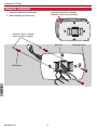
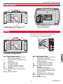
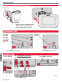
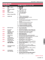
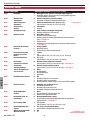
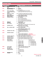
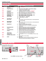
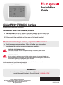
Installation
Guide
VisionPRO TH8000 Series
®
Touch-screen Programmable Thermostat
This manual covers the following models
• TH8321U1097: For up to 3 Heat/2 Cool heat pump or up to 2 Heat/2 Cool
conventional systems with dehumidification, humidification, or ventilation
(Pull thermostat from wallplate and turn over to find model number)
Must be installed by a trained, experienced technician
• Read these instructions carefully. Failure to follow these instructions
can damage the product or cause a hazardous condition.
CAUTION: ELECTRICAL HAZARD
Can cause electrical shock or equipment damage. Disconnect power before
beginning installation.
MERCURY NOTICE
If this product is replacing a control that contains mercury in a sealed tube, do not
place the old control in the trash. Contact your local waste management authority for
instructions regarding recycling and proper disposal.
This thermostat contains a Lithium battery which may contain Perchlorate material.
Perchlorate Material—special handling may apply,
See www.dtsc.ca.gov/hazardouswaste/perchlorate
Need Help?
For assistance with this product please visit http://customer.honeywell.com
or call Honeywell Customer Care toll-free at 1-800-468-1502
® U.S. Registered Trademark.
US Patent No. 6595430, D509151 and other patents pending.
Copyright © 2011 Honeywell International Inc.
All rights reserved.
69-2389-03
Installation Guide
Wallplate installation
1. Separate wallplate from thermostat.
Grasp top and bottom of wallplate
and pull to remove from thermostat.
2. Mount wallplate as shown below.
+
+
+
Drill 3/16” holes for drywall.
Drill 7/32” holes for plaster.
MCR29480
Wire hole
Mounting screws
Wall anchors
ENGLISH
MCR29481
69-2389—03
2
VisionPRO TH8000 Series
TM
Power options
R
U1
U1
E/AUX
U1
U1
MCR29723
Insert supplied batteries for
primary or backup power.
For 24VAC primary power, connect common
side of transformer to “C” terminal.
Wiring
Push excess wire back into the wall opening. Plug
wall opening with non-flammable insulation.
R
U1
U1
E/AUX
U1
U1
MCR29724
Terminal Designations
Heat Pump Terminal Letters:
R
System power. Connect to secondary
side of system transformer.
C
Common wire from secondary side of
system transformer.
Y
1st stage compressor contactor.
Y2
2nd stage compressor contactor.
E/Aux Auxiliary/Emergency heat relay.
G
Fan relay.
L
Heat pump reset (powered
continuously when System is set to
Em Heat; system monitor when set to
Heat, Cool or Off).
O/B Changeover valve for heat pumps.
S1/S2 Optional outdoor/remote/discharge
sensor.
U1/U1 Optional IAQ device
3
69-2389—03
ENGLISH
Conventional Terminal Letters:
R
System power. Connect to secondary
side of system transformer.
C
Common wire from secondary side of
transformer.
W
1st stage heat relay.
W2
2nd stage heat relay.
Y
1st stage compressor contactor.
Y2
2nd stage compressor contactor.
G
Fan relay.
S1/S2 Optional outdoor/remote/discharge
sensor.
U1/U1 Optional IAQ device
Installation Guide
Wiring
Wiring guide—conventional systems
1H/1C System (1 transformer)
2H/2C System (1 transformer)
R
W
Y
G
C
S1/S2
Y2
W2
R
W
Y
G
C
S1/S2
Power [1, 6]
Heat relay
Compressor contactor
Fan relay
24VAC common [2]
Optional outdoor/remote/discharge
sensor
U1/U1 Optional IAQ relay
Cool relay 2
Heat relay 2
Power [1, 6]
Heat relay 1
Cool relay 1
Fan relay
24VAC common [2]
Optional outdoor/remote/discharge
sensor
U1/U1 Optional IAQ relay
Heat Only System
R
W
C
S1/S2
Power [1]
Heat relay
24VAC common [2]
Optional outdoor/remote/discharge
sensor
U1/U1 Optional IAQ relay
Heat Only System With Fan
R
W
G
C
S1/S2
Power [1, 6]
Heat relay
Fan relay
24VAC common [2]
Optional outdoor/remote/discharge
sensor
U1/U1 Optional IAQ relay
Heat Only System (Series 20)
R
W
Y
C
S1/S2
Series 20 valve terminal “R” [1]
Series 20 valve terminal “B”
Series 20 valve terminal “W”
24VAC common [2]
Optional outdoor/remote/discharge
sensor
U1/U1 Optional IAQ relay
Cool Only System
R
Y
G
C
S1/S2
Power [1]
Compressor contactor
Fan relay
24VAC common [2]
Optional outdoor/remote/discharge
sensor
U1/U1 Optional IAQ relay
ENGLISH
See [notes] below
[1] Power supply. Provide disconnect means and overload protection as required.
[2] Optional 24VAC common connection.
[6] Only works with single transformer systems.
69-2389—03
4
VisionPRO TH8000 Series
TM
Wiring
Wiring guide—heat pump systems
1H/1C Heat Pump (no auxiliary heat)
2H/2C Heat Pump (no auxiliary heat)
R
O/B
Y
G
C
S1/S2
Y2
R
O/B
Y
G
C
S1/S2
Power [1]
Changeover valve [3]
Compressor relay
Fan relay
24VAC common [2]
Optional outdoor/remote/discharge
sensor
U1/U1 Optional IAQ relay
Compressor 2 relay
Power [1]
Changeover valve [3]
Compressor 1 relay
Fan relay
24VAC common [2]
Optional outdoor/remote/discharge
sensor
U1/U1 Optional IAQ relay
2H/1C Heat Pump (with auxiliary heat)
3H/2C Heat Pump (with auxiliary heat)
L
E/Aux
R
O/B
Y
G
C
S1/S2
Equipment monitor [4, 5]
Auxiliary/emergency heat relay
Power [1]
Changeover valve [3]
Compressor relay
Fan relay
24VAC common [2, 4]
Optional outdoor/remote/discharge
sensor
U1/U1 Optional IAQ relay
Y2
L
E/Aux
R
O/B
Y
G
C
S1/S2
Compressor 2 relay
Equipment monitor [4, 5]
Auxiliary/Emergency heat relay
Power [1]
Changeover valve [3]
Compressor 1 relay
Fan relay
24VAC common [2, 4]
Optional outdoor/remote/discharge
sensor
U1/U1 Optional IAQ relay
Wiring guide—humidification systems
Steam humidifier (or any humidifier with
its own transformer)
R
U1
U1
Bypass, flow-through humidifier (or any
humidifier that uses the system transformer)
Power [1]
Humidifier relay [7]
Humidifier relay [7]
R
U1
U1
Power [1]
Field jumper R to U1 [7]
Humidifier relay [7]
Wiring guide—dehumidification systems
Whole house dehumidifier
A/C with low-speed fan
R
U1
U1
Power [1]
Dehumidifier relay [7]
Dehumidifier relay [7]
Power [1]
Field jumper R to U1 [7]
Dehumidifier relay [8]
ENGLISH
R
U1
U1
Wiring guide—ventilation systems
Whole house powered ventilator
R
U1
U1
Non-powered ventilator
R
U1
U1
Power [1]
Ventilator relay [7]
Ventilator relay [7]
Power [1]
Field jumper R to U1 [7]
Ventilator relay
See [notes] below
[1] Power supply. Provide disconnect means and overload protection as required.
[2] Optional 24VAC common connection.
[3] O/B set to control as either O or B in installer setup.
[4]If L terminal is used, 24VAC common (terminal C) must be connected.
[5] Heat pump reset (powered continuously when thermostat is set to Em. Heat; system monitor
when set to Heat, Cool, or Off).
[7] Terminals are normally open dry contacts.
[8] Equipment must include dehumidification terminal for low-speed fan.
5
69-2389—03
Installation Guide
Remove tab and mount thermostat
Remove tab.
Align pins on back of thermostat with
slots in wallplate, then push gently
until thermostat snaps into place.
MCR29484
Set date and time
Press st
to set date
Press st
to set time
TUE
Press st
to set month
TUE
15
Press st
to set year
2010
6
1:00 PM
DONE
DONE
MCR29746
Press DONE to save changes.
Press DONE to save and exit.
Installer setup
ENGLISH
1Press SYSTEM
2 Press and hold for 5 seconds
Press DONE to save & exit
3 Change settings (see p. 7-9)
SYSTEM
TUE
FAN
AUTO
Inside
70
SYSTEM
HEAT
HEAT
0120
6:00aM
DONE
DONE
6:00aM
SCHED
CANCEL
Function
0120
HOLD
Setting
20
DONE
MCR29745
Press s t to change
69-2389—03
20
6
VisionPRO TH8000 Series
TM
Installer setup
Setup functions
0120
0140
0150
0160
Year
(first two digits)
Year
(second two digits)
Month
Date
Schedule format
0165
Restore energy saving
0170
System type
0173
Heat Pump Type
0180
Fan control
(heating)
Changeover valve
(O/B terminal)
Auxiliary heat
0130
0190
0200
0210
0220
0230
0250
2nd stage heat cycle
rate (CPH)
0260
3rd stage heat
cycle rate (CPH)
Continued on next page
7
69-2389—03
ENGLISH
0240
External fossil
fuel kit
1st stage compressor cycle rate
2nd stage compressor cycle rate
1st stage heat
cycle rate (CPH=
cycles per hour)
Settings & Options (factory default in bold)
20(2000-2099)
21(2101-2178)
10(2010)
[Other options: 00-99]
6 [Other options: 1-12]
15 [Other options: 1-31]
4 7-day programming
0Non-programmable
0No
1Yes
1 1 heat/1 cool conventional
2 1 heat/1 cool heat pump (no aux. heat)
3 Heat only (2-wire systems)
4 Heat only with fan
5 Hot water Series 20 system (power to open & close zone
valves/normally open zone valves)
6 Cool only
7 2 heat/1 cool heat pump (with aux. heat)
8 2 heat/2 cool multistage conventional
9 2 heat/1 cool multistage conventional
10 1 heat/2 cool multistage conventional
11 2 heat/2 cool heat pump (no aux. heat)
12 3 heat/2 cool heat pump (with aux. heat)
0 Air to Air heat pump
1 Geothermal heat pump
0 Gas/Oil heat (equipment controls heating fan)
1 Electric furnace (thermostat controls heating fan)
0 O/B terminal controls valve in cooling
1 O/B terminal controls valve in heating
0 Electric backup heat
1 Fossil fuel backup heat
1 External fossil fuel kit controls backup heat
0 Thermostat controls backup heat (outdoor sensor required)
3 Recommended for most compressors
[Other options: 1, 2, 4, 5 or 6 CPH]
3 Recommended for most compressors
[Other options: 1, 2, 4, 5 or 6 CPH]
5 Gas or oil furnaces of less than 90% efficiency
1 Steam or gravity systems
3 Hot water systems & furnaces of 90%+ efficiency
9 Electric furnaces
[Other options: 2, 4, 6, 7, 8, 10, 11, 12 CPH]
5 Gas or oil furnaces of less than 90% efficiency
1 Steam or gravity systems
3 Hot water systems & furnaces of 90%+ efficiency
9 Electric furnaces
[Other options: 2, 4, 6, 7, 8, 10, 11, 12 CPH]
9 Electric auxiliary heat or electric furnaces
1 Steam or gravity systems
3 Hot water systems & furnaces of 90%+ efficiency
5 Gas or oil furnaces of less than 90% efficiency
[Other options: 2, 4, 6, 7, 8, 10, 11, 12 CPH]
Installation Guide
Installer setup
Setup functions
0280
Backlight
0300
0330
Manual/Auto
changeover
Auto changeover
deadband
Temperature
display
Daylight savings
0340
Remote sensor
0345
Dual Fuel Heat Pump
Control **
0346
Dual fuel heat pump
upstage to furnace
timer **
Droop temperature
0310
0320
0347
0350
0360
0371
Heat pump
compressor lockout
Heat pump
auxiliary lockout
Indoor Air Quality device on U1/U1
ENGLISH
0372
Humidification Control
0374
Hum fan action
0379
Dehumidification
Control
0380
Dehumidify with air
conditioner
0383
Over cooling limit
0384
Dehumidification fan
control
Whole house dehumidification lockout
0386
69-2389—03
Settings & Options (factory default in bold)
0
1
Backlight on for approx. 8 seconds after keypress
Backlight always on low intensity, full bright after keypress
(requires 24VAC connection)
0 Manual changeover (Heat/Cool/Off)
1 Automatic changeover (Heat/Cool/Auto/Off)
3 Heat/cool temperature 3°F apart (1.5°C) ** See page 11
[Other options: 2-9 (2°F to 9°F/1°C to 5°C)]
0Fahrenheit
1 Celsius
2 Auto-change to daylight saving time
0 Daylight saving time is turned off
0 No remote sensor
1 Outdoor sensor (display only)
2 Outdoor sensor for control (select lockouts and frost protection) ** See page 11
3 Indoor sensor
4 Discharge air sensor (Required for Desert humidity control)
** See page 11
1 Droop Control
0 No droop control
2 Droop control with aux heat lockout
1 1 hour
0Off
[Other options: 0.5, 1.5, 2-6, 8, 10, 12, 14, 16 hours]
2 2°F (1°C)
[Other options: 2-5 (2°F to 5°F/1°C to 2.5°C)]
0 No heat pump compressor lockout
[Other options: 5–60°F (-15°C to 15.5°C)] ** See page 11
0 No heat pump auxiliary lockout
[Other options: 5–65°F (-15°C to 18.5°C)] ** See page 11
0None
1 Humidification
2 Dehumidification
3Ventilation
0Off
1 Humidify with no frost protection
3 Humidify with frost protection
8 Desert humidity control in heat, off, or cool; DATS required
0 Humidify only while fan is on
1 Humidifier forces fan on
2 Humidify only when heat it on
3 Humidifier operates independent of fan
0None
1 Air conditioning with low speed fan
3 Whole house dehumidification
0 No dehumidification control
1 Thermostat controls dehumidification with air conditioner
high speed fan ** See page 11
3 3°F (1.5°C)
[Other options: 1-2 (1°F to 2°F/.5°C to 1°C)]
0 Fan turns on with dehumidifier
1 Dehumidifier operates independent of fan
0Off
** See pages 11–12
1On
Continued on next page
8
VisionPRO TH8000 Series
TM
Installer setup
Setup functions
0390
0391
0392
0393
0394
0400
0401
Dehumidification Away
Mode
Dehumidification Away
Mode Fan Setting
Dehum. Away Mode
Low Limit Temperature
Setting
Dehum. away mode
temp. setting
Dehum. Away Mode
Dehum. Setting
Ventilation control
0403
Ventilation level
0404
Max. ventilation limit
0405
Ventilation fan action
0430
Ventilation lockout
0431
Ventilation high temperature lockout
Ventilation low temperature lockout
Furnace filter
change reminder
0432
0500
0502
0510
0520
Furnace filter
alert options
Humidifier pad
change reminder
UV lamp change
reminder
85 Low limit away temperature 85°F (29°C)
[Other options: 70°F to 99°F (21°C to 37°C)]
65 Away humidity level 65%
[Other options: 40% to 70%]
0 No ventilation
1 Vent on during all periods
2 Vent off during sleep period
3 Vent on during all periods with lockouts
4 Vent off during sleep period with lockouts
2 Two bedrooms
[Other options: 1 to 6]
10 1,000 square feet}
[Other options: 11 to 50 (1,100 to 5,000 square feet)]
160 CFM (cubic feet per minute)
[Other options: (30 to 195 CFM)]
50 50% ventilation limit
[Other options: 30% to 60% or 100%]
P Meets ASHRAE 62.2 standard
F Does not meet ASHRAE 62.2 standard
1 Ventilation on forces fan on
2 Ventilation does not force fan on
0Off
1 Lockout for high temperatures ** See page 11
2 Lockout for low temperatures ** See page 11
3 Lockout for high and low temperatures ** See page 11
100 100°F (38°C): Settings 5°F apart (3°C)
[Other options: (90°F to 110°F/32°C to 43.5°C)]
-10 -10°F (-23.5°C): Settings 5°F apart (3°C)
[Other options: (-20°F to 0°F/-29°C to -18°C)]
0 Off
8365-day run time
1 10-day run time
930 calendar days
2 30-day run time
10 60 calendar days
3 60-day run time
11 90 calendar days
4 90-day run time
12 120 calendar days
5 120-day run time
13 180 calendar days
6 180-day run time
14 365 calendar days
7 270-day run time
0 Timer counts Heat & Cool run time
1 Timer counts Cool run time only
0Off
1 90 calendar days
2 180 calendar days
3 365 calendar days
0Off
1 1 year
2 2 years
Continued on next page
9
69-2389—03
ENGLISH
0402
Number of
bedrooms
Size of home
Settings & Options (factory default in bold)
0No
1Yes
0 Fan auto
1 Fan on
2 Fan circulate
76 Low limit temperature 76°F (24°C)
[Other options: 70°F to 80°F (21°C to 27°C)]
Installation Guide
Installer setup
Setup functions
0530
0540
0580
0600
0610
0640
Settings & Options (factory default in bold)
Adaptive Intelligent
Recovery™
Program periods
Compressor
protection
Heat temperature
range stop
Cool temperature
range stop
Clock format
0650
Extended fan
timer (heat)
0660
Extended fan
timer (cool)
0670
Keypad lock
0680
Heat temperature
control
0690
Cool temperature
control
0700
0701
Temperature
display offset
Humidity display offset
0710
RESET
1On ** See page 11
0Off
4 4 program periods (Wake, Leave, Return, Sleep)
2 2 program periods (Wake, Sleep)
5 5 minute compressor off time ** See page 11
[Other options: 0, 1, 2, 3 or 4-minute off time]
90 Max. heat temperature setting is 90°F (32°C)
[Other options: 40-89°F (4°C to 32°C)]
50 Min. cool temperature setting is 50°F (10°C)
[Other options: 51-99°F (11°C to 37°C)]
12 12-hour time (i.e., “3:30 pm”)
24 24-hour time (i.e., “15:30”)
0Off
[Other options: Fan runs for 30, 60, 90, or 120 seconds after
call for heat ends]
0Off
[Other options: Fan runs for 30, 60, 90, or 120 seconds after
call for cool ends]
0 Keypad unlocked (fully functional)
1 Partially locked (access to temperature settings only)
2 Fully locked
2 Standard temperature control (recommended)
1 Choose if room is warmer than set temperature
3 Choose if room does not reach set temperature
2 Standard temperature control (recommended)
1 Choose if room is cooler than set temperature
3 Choose if room does not reach set temperature
0 Thermostat displays actual room temperature
[Other options: -3, -2, -1, 1, 2, 3°F offset (-1.5°C to 1.5°C)
00%
[Other options: -12% to 12%]
0 No reset
1 Reset installer options & program schedule to factory default (only date and time settings are retained)
ENGLISH
Installer system test
During installer setup, press t
repeatedly until “Test” appears.
0120
System
status
Test
number
1
20
DONE
TEST
0
DONE
Press DONE to terminate testing.
69-2389—03
10
Press st to
select test
MCR29488
Press st to
change status
VisionPRO TH8000 Series
TM
Installer system test
System test
1 Cooling system
2
Fan system
3
Heating system
4
5
Emergency
heating system
Humidifier
6
Dehumidifier
7
Ventilator
System status
0 Compressor and fan turn off
1 Compressor and fan turn on
2 Second stage compressor turns on
0 Fan turns off
1 Fan turns on
0 Heat and fan turn off
1 Heat turns on (fan on if Function 0170 is set for heat pump,
or if Function 0180 is set to “1”) ** See page 6
2 Second stage heat turns on
3 Third stage heat turns on
0 Heat and fan turn off
1 Heat and fan turn on
CAUTION: EQUIPMENT
0Off
DAMAGE HAZARD.
1 Humidifier on
Compressor protection
0Off
is bypassed during test1 Dehumidifier on
ing. To prevent equipment
0Off
damage, avoid cycling the
1 Ventilator on
compressor quickly.
Special functions
Auto Changeover (Setup Function 0300): When set to Auto, the thermostat automatically selects heating
or cooling depending on the indoor temperature. Heat and cool settings must be at least 2 degrees apart. If
function 0380 is set to On, the heat and cool settings must be at least 5 degrees apart.
Remote Sensor (Setup Function 0340): If an optional outdoor sensor is installed, the thermostat can display
the outside temperature. If an optional remote indoor sensor is installed, the thermostat will display the temperature at the sensor location (the internal sensor in the thermostat is not used). A Discharge Air Temperature Sensor (DATS) is required to enable desert humidification.
Adaptive Intelligent Recovery (Setup Function 0530): Allows the thermostat to “learn” how long the furnace
and air conditioner take to reach programmed temperature settings, so the temperature is reached at the
scheduled time.
Compressor Protection (Setup Function 0580): Forces the compressor to wait a few minutes before restarting, to prevent damage. During this time, the message “Wait” is displayed.
Dehumidification control (Setup Function 0380): TH8321 models monitor the indoor humidity level and
automatically activate the cooling system to reduce humidity by lowering the temperature by up to 3 degrees
below the current cool setting. When Setup Function 0371 is set to dehumidification, the U1/U1 relay can be
set to control dehumidification.
ENGLISH
Heat Pump Control — Electric Backup (Setup Functions 0350-0360): If an outdoor temperature
sensor is installed, select a compressor lockout temperature (Function 0350). Below this temperature,
only electric heat operates. Also select an auxiliary lockout temperature (Function 0360). Above this
temperature, only the compressor operates. Between these temperatures, both heat sources operate.
Heat Pump Control — Fossil Fuel Backup (Setup Function 0345):
Option 0 (No Droop Control): If outdoor temperature is above balance point (Function 0350), only the
compressor operates. Below this temperature, only backup heat operates.
Option 1 (Droop Control): As above, but backup heat is activated if room temperature drops to the
selected droop temperature setting (compressor is deactivated).
Option 2: (Droop Control with Aux Heat lockout): Compressor works only above auxiliary lockout
temperature, backup heat works only below balance point, 2° droop between temperatures.
If temperature is not reached in a reasonable time, set the upstage timer (Function 0346). After the
designated time, the compressor will be deactivated and the system will switch to backup heat.
Ventilation Control (Setup Functions 0400-0432): If the system includes a self-powered ventilation unit
(Function 0400), the home can be ventilated on demand. Ventilation can also be locked out based on high
and low outdoor temperature (Function 0431 & 0432)—outdoor temperature sensor required.
Dehumidification Away Mode (Setup Functions 0390-0394): This feature is useful for homes in southern
climates. It allows humidity control when the the home is unoccupied for long periods during the hot/humid
season. You can control temperature (Function 0393) and dehumidification (Function 0394) while away. You
can control humidity with a dehumidifier or a cooling system (Function 0379). If a cooling system is used,
humidity is controlled by cooling indoor air to the Low Limit Temperature (Function 0392). When the desired
humidity is reached, the system will maintain the temperature you select in Function 0393.
Indoor Air Quality Device (Setup Function 0371): This feature allows the thermostat to control one of the following IAQ devices: whole house humidifier, dehumidifier, or ventilator.
11
69-2389—03
Installation Guide
Accessories & replacement parts
Please contact your distributor to order replacement parts.
Outdoor temperature sensor................................................Part Number C7089U1006
Remote indoor temperature sensor....................................Part Number C7189U1005
Discharge air temperature sensor......................................Part Number C7735A1000
Energy recovery ventilator...................................................Part number ER200B2006
Heat recovery ventilator.......................................................Part number HR200B1005
Fresh air damper...................................................................Part number EARD6
Bypass flow through humidifier..........................................Part number HE265A1007
TrueSTEAM humidifier...........................................................Part number HM512W1005
Cover plate*............................................................................Part Number 32003796-001
*(Use to cover marks left by old thermostats.)
Specifications
Temperature Ranges
• Heat: 40° to 90°F (4.5° to 32°C)
• Cool: 50° to 99°F (10° to 37°C)
Operating Ambient Temperature
• 0° to 120°F (-18° to 48.9°C)
Shipping Temperature
• -30° to 150°F (-34° to 66°C)
Operating Relative Humidity
• 5% to 90% (non-condensing)
Physical Dimensions
• 4-9/16” H x 6” W x 1-3/8” D
• 116 mm H x 152 mm W x 35 mm D
Electrical Ratings
Terminal
Voltage (50/60Hz)
W Heating
20-30 Vac
(Powerpile)
750 mV DC
W2 Heating
20-30 Vac
Y Cooling
20-30 Vac
Y2 Cooling
20-30 Vac
E/Aux Auxiliary/
Emergency heat
20-30 Vac
O/B Changeover
20-30 Vac
L Heat pump reset
20-30 Vac
U1/U1 IAQ relay
20-30 Vac
20-30 Vac
Running Current
0.02-1.0 A
100 mA DC
0.02-0.6 A
0.02-1.0 A
0.02-0.6 A
Automation and Control Solutions
Honeywell International Inc.
Honeywell Limited-Honeywell Limitée
1985 Douglas Drive North
35 Dynamic Drive
Golden Valley, MN 55422
Toronto, Ontario M1V 4Z9
http://yourhome.honeywell.com
® U.S. Registered Trademark.
US Patent No. 6595430, D509151 and other patents pending.
© 2011 Honeywell International Inc.
69-2389—03 M.S. Rev 03-11
Printed in U.S.A.
0.02-1.0 A
0.02-0.6 A
0.02-0.6 A
0.02-0.6 A