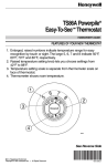
1
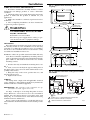
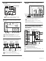
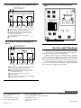
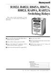
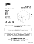
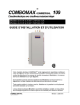
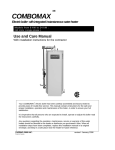
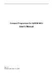
TRADELINE ®
R182J, R482J, R845A,
R847A, RA89A, RA832A
Switching Relays
Application
These relays can be used for a variety of switching applications. Typically they provide control of line- or low-voltage
devices by a low voltage controller. See Table 1.
TABLE 1—SWITCHING RELAY SPECIFICATIONS.
Models
R182J
R482J
a
Application
For 24V thermostat
control of line voltage
devices.
Controlled by a line
voltage controller
R845A
For hot water zone control
systems or spst control of
two separate loads.
R847A
Provides switching for
high-current loads such as
cooling compressors.
RA89A
For switching one line
voltage load.
RA832A
For switching two line
voltage loads with a
common power source.
Voltage
(50/60 Hz)
Switch
Action
Control
Circuit
Coil
Voltage
(Vac at
50/60 Hz)
120
Dpdt
3-wire
24
Relay Coil
Current
(A)
0.40 a
Contact
Ratings (A)
AFL ALR
240
120
2-wire
7.4
44.4
3.7
22.2
120
0.08
7.4
44.4
208/240
0.04
3.7
22.2
24
0.40
7.4
44.4
120
22
100
240
10
50
10.2
61.2
208/240
120
Dpst
120
Spst
120
Dpst
240
IMPORTANT: The transformer on the R182 can overheat when used with a series 20 thermostat if the
total resistance of the thermostat circuit exceeds
2.5 ohms. If the measured resistance of the thermostat (including thermostat wire and thermostat contact resistance) exceeds 2.5 ohms, add a 100 ohm,
10 watt resistor between the W and R terminals.
Table 2 gives maximum thermostat wire runs; if
longer runs are necessary, measure the resistance or
add a 100 ohm, 10 watt resistor across terminals W
and R.
7.4
44.4
3.7
22.2
TABLE 2—LENGTH OF WIRE.
Length of Run
to Thermostat
(Wires)
AWG
Wire
Size
(Number)
Feet
Meters
Feet
22
120
38.0
60
18.0
20
200
61.0
100
30.5
18
300
91.5
150
45.5
16
500
152.5
250
76.0
14
800
244.0
400
122.0
Total Wire
Length
Meters
J.H. • Rev. 10-94
1 • ©Honeywell Inc. 1994 • Form Number 69-0791—3
Installation
Fig. 1—Approximate mounting dimensions in
in. [mm].
WHEN INSTALLING THIS PRODUCT…
1. Read these instructions carefully. Failure to follow
instructions can damage product or cause a hazardous
condition.
2. Check the ratings given in the instructions and on the
product to make sure the product is suitable for your
application.
3. Make sure installer is a trained, experienced service
technician.
4. After completing installation, use these instructions
to check out product operation.
4
5
1 [29]
32
1
[108]
4
7
8
[48]
1
7
[22] DIAMETER
8
3
[2] DIAMETER
32
1
[13] DIAMETER
2
WARNING
KEYHOLE TYPE
MOUNTING HOLE
ELECTROCUTION HAZARD CAN
CAUSE PROPERTY DAMAGE, SEVERE
INJURY, OR DEATH.
Transformer core not bonded.
1
2
[114]
4
Disconnect power supply before wiring to prevent electrical shock or equipment damage.
1
4
[133]
5
MOUNTING
For replacement, mount the relay in the same location as
the old relay. If this is a new installation, locate the relay
vertically on a solid wall or partition as close as possible to
the device to be controlled. Select a location that is easily
accessible for installation and service.
3
[10]
8
1
3 [89]
2
7
[6] DIAMETER MOUNTING HOLE
32
NOTE: To reduce the possible transformer hum and relay
noise that is sometimes amplified by mounting surfaces
such as sheetmetal, plasterboard, and similar materials,
place rubber or felt washers between the case and the
mounting surface.
15
2
16
[75]
7
8
[48]
1
1. Position the relay and mark the mounting holes. See
Fig. 1.
2. Start a screw for the keyhole type mounting hole in
the upper right corner. Screw it down within about 1/8 in.
[3 mm] of the surface.
3. Hang the relay on the screw, position the case, and
start the bottom screw.
4. Tighten both screws.
25
[20]
32
1
KNOCKOUT FOR
1/2 (13) CONDUIT (3)
3
[35]
8
M3823
Fig. 2—Internal schematic and typical hookup
for RA89A.
LOW VOLTAGE (CLASS 2)
2-WIRE THERMOSTAT
WIRING
All wiring must comply with all applicable electrical
codes, ordinances, and regulations. Follow any instructions
furnished with the controlled equipment.
T
T
RA89A (SPST)
RA89A
2
JUMPER REMOVED
2
IMPORTANT: The switching relay terminals are approved for use with copper wires only.
1
3
4
JUMPER
2
See Figs. 2 through 9 for hookup diagrams for these
relays. When two or more devices are to be controlled in
parallel, the total current must not exceed the relay load
rating. Fig. 11 is an internal view of the RA832A showing
terminal locations and barriers.
Never connect load terminals to a load that takes more
current than the amount listed in the electrical ratings on the
relay.
69-0791—3
3 [10]
8
1
3
4
L2
1
CONTROLLER
(IF USED)
L2
2
1
L1
HOT
TO LOAD
L1
HOT
1
TO LOAD
1
POWER SUPPLY. PROVIDE OVERLOAD PROTECTION
AND DISCONNECT MEANS AS REQUIRED.
2
COMPLETE WIRING AS SHOWN ABOVE.
M3819
Fig. 3—Internal schematic and typical hookup
for RA832A.
LOW VOLTAGE (CLASS 2)
2-WIRE THERMOSTAT
Fig. 6—Internal schematics and typical hookup
for R482J.
R482J
AUXILIARY TO LOW
OR MILLIVOLTAGE
(POWERPILE) LOAD
RA832A
T
T
2
1
X
X
3
3
1
CONTROLLER
L2
1
LOAD 1
L1
HOT
1
LOAD 2
(OPTIONAL)
R
3
OHMS
6
7
8
N.O.
N.C. COM.
TO LOAD
TO LOAD
POWER SUPPLY. PROVIDE OVERLOAD PROTECTION
AND DISCONNECT MEANS AS REQUIRED.
2
CONTROLLER (IF USED) MUST BE SNAP ACTION OR
MERCURY SWITCH TYPE.
3
N.O. CONTACTS MAKE BEFORE N.C CONTACTS BREAK,
AND N.C. CONTACTS MAKE BEFORE N.O. CONTACTS BREAK.
M8234
K1
K1
Fig. 7—Schematic diagram showing R845A in
multizone, forced hydronic heating system.
This arrangement is suitable for any number of
additional zones.
L2
2
K2
K1
4
3
HYDRONIC HEATING
CONTROL TERMINALS
6
7
T
LOAD
L1
L2
(HOT)
3
B
K2
L1
5
1
R182J
X
4
N.O. N.C. COM.
L2
Fig. 4—Internal schematic and typical hookup
for R182J.
2
2
L1
(HOT)
1 POWER SUPPLY. PROVIDE OVERLOAD PROTECTION
AND DISCONNECT MEANS AS REQUIRED.
M3821
W
3
4
1
N.O.
N.C.
N.O.
RA845A RELAY
THERM. THERMOSTAT
ZONE 1
T
LOAD
N.C.
TO ADDITIONAL R845A
RELAYS FOR OTHER ZONES
2
1
POWER SUPPLY. PROVIDE OVERLOAD PROTECTION AND
DISCONNECT MEANS AS REQUIRED.
2
N.O. CONTACTS MAKE BEFORE N.C CONTACTS BREAK,
AND N.C. CONTACTS MAKE BEFORE N.O. CONTACTS BREAK.
THERMOSTAT
ZONE 2
1
ZC
4
ZP
3
B1
BURNER BURNER
CONTROL
B2
M8232
5
6
C1
Fig. 5—Thermostat connections for R182J.
CIRC.
CIRCULATOR
ZONE 1
CIRCULATOR
ZONE 2
C2
THREE-WIRE
LOW VOLTAGE
(SERIES 10)
THERMOSTAT 1
W
R
THREE-WIRE
LOW VOLTAGE
(SERIES 20)
2
THERMOSTAT
B
B
W
TWO-WIRE
LOW VOLTAGE
(SERIES 80)
THERMOSTAT
1
LINE
2
1
L1
HOT
L2
2
3
R
1 POWER SUPPLY. PROVIDE OVERLOAD PROTECTION
AND DISCONNECT MEANS AS REQUIRED.
W
X
R
B
W
X
R
B
W
X
R
2 IF CONTROLLING TWO LOADS, USE:
3 AND 4 FOR LINE VOLTAGE LOAD
5 AND 6 FOR LINE OR LOW VOLTAGE LOAD
B
3 IF USING LOW VOLTAGE, USE A SEPARATE TRANSFORMER.
R182J
R182J
M3822
R182J
JUMPER
1 MAKES CONTACT ON TEMPERATURE FALL ONLY.
2 MAKES CONTACT ON BOTH A TEMPERATURE RISE AND FALL.
M8233A
3
69-0791—3
Fig. 8—R845A hookup for controlling two loads.
Fig. 10—Internal view of RA832A Switching
Relay.
LOW VOLTAGE (CLASS 2)
2-WIRE THERMOSTAT
T
X
T
X
R845A
T
T
2
1
4
3
5
RELAY
6
24V TRANSFORMER
3
1
2
1
L1
HOT
L2
TO
POWER
1
TO
POWER
LOAD 1
LOAD 2
1
POWER SUPPLY. PROVIDE OVERLOAD PROTECTION
AND DISCONNECT MEANS AS REQUIRED.
2
WHEN CONTROLLING TWO LOADS, USE 3 AND 4
FOR LINE VOLTAGE LOAD AND 5 AND 6 FOR LINE
OR LOW VOLTAGE LOAD.
3
IF USING LOW VOLTAGE, USE A SEPARATE
TRANSFORMER.
2
1
M3820
3
4
M3824
Fig. 9—Internal schematics and hookup for
R847A.
LOW VOLTAGE (CLASS 2)
2-WIRE THERMOSTAT
Service and Checkout
R847A
T
T
L2
L1
4
3
7
4
1. Never use oil on any part of the relay coil or contacts.
2. Keep the cover on the relay during normal operation
and remove only for service and checkout.
3. Relay contacts require no cleaning; they are arranged
so they close with a wiping action and are self-cleaning.
The contacts may turn black after being in service for some
time; this discoloration does not prevent proper operation.
4. After installation is complete, operate system through
at least one cycle from the controller to make certain the
relay controls the equipment as intended.
6
4
3
1
L2
2
1
TO
L1
POWER
(HOT)
LOAD 1
1
TO
POWER
LOAD 2
1
POWER SUPPLY. PROVIDE OVERLOAD PROTECTION
AND DISCONNECT MEANS AS REQUIRED.
2
WHEN CONTROLLING TWO LOADS, USE 3 AND 4
FOR LINE VOLTAGE LOAD AND 5 AND 6 FOR LINE
OR LOW VOLTAGE LOAD.
3
IF USING LOW VOLTAGE, USE A SEPARATE
TRANSFORMER.
4
10 AMP CONTACT RATING OR 20 AMP WHEN POLES
ARE CONNECTED IN PARALLEL.
M8231B
Home and Building Control
Honeywell Inc.
1985 Douglas Drive North
Golden Valley, MN 55422
69-0791—3
Printed
in U.S.A.
Home and Building Control
Honeywell Limited—Honeywell Limitée
740 Ellesmere Road
Scarborough, Ontario
M1P 2V9
4
Helping You Control Your World
QUALITY IS KEY