1
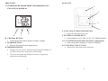
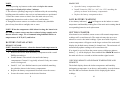
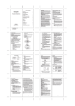
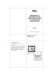
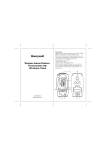
Honeywell
Wireless Thermo-Hygrometer
TABLE OF CONTENTS
INTRODUCTION
3
PRODUCT OVERVIEW
4
REMOTE SENSOR
7
BEFORE YOU BEGIN
8
BATTERY INSTALLATION
9
LOW BATTERY WARNING
10
GETTING STARTED
10
COMFORT LEVEL INDICATORS
11
MAXIMUM AND MINIMUM MEMORY
12
AUTO-SCANNING
12
LOST COMMUNICATION
13
TRANSMISSION COLLISION
14
PRECAUTIONS
14
SPECIFICATIONS
16
FCC STATEMENT
17
DECLARATION OF CONFORMITY
18
STANDARD WARRANTY INFORMATION
19
(TM005X)
USER MANUAL
2
INTRODUCTION
PRODUCT OVERVIEW
Thank you for selecting the Honeywell Wireless Thermo-Hygrometer
with Remote Sensor. This device monitors and displays temperature
and humidity both indoors and outdoors from up to three remote
locations.
In this package you will find:
MAIN UNIT
FEATURES
• One main unit (receiver)
• One remote sensor (transmitter) TS33
• One User Manual
Please keep this manual handy as you use your new item. It contains
practical step-by-step instructions, as well as technical specifications
and precautions you should know.
3
•
Wireless transmission of the temperature and humidity from the
remote sensor to the main unit from up to 100 feet (30 meters)
away
•
•
•
•
•
•
Indoor temperature and relative humidity display
Remote temperature and relative humidity display
Auto scan feature
Comfort level indicator
User-selectable temperature display in Celsius or Fahrenheit
Memory for the indoor and remote temperature and humidity
readings
•
•
Wall mount or desktop option
Low battery indicator
3
4
REAR VIEW
FRONT VIEW
A. TEMPERATURE AND HUMIDITY INFORMATION IN A
TWO LINE LCD DISPLAY
E
F
G
H
E. WALL-MOUNT RECESSED OPENING
B
D
C
B. CHANNEL BUTTON
• Selects the desired remote channel or indoor readings
C. SEARCH BUTTON
• Enforces the remote sensors signal search
D. MEMORY BUTTON
•
Toggles between current, minimum and maximum readings of
the indoor and remote temperature and humidity
•
Clears the maximum and minimum memory of registered
temperature and humidity
5
• Keeps the main unit on the wall
F. BATTERY COMPARTMENT
• Accommodates 2 (two) UM-3 or AA 1.5V alkaline batteries.
G. C°/F° SWITCH (located inside the battery compartment)
• Selects temperature display in Celsius or Fahrenheit
H. UNFOLDING TABLE STAND
•
Supports the main unit on the flat surface
5
6
• Selects the desired channel
E. WALL-MOUNT RECESSED OPENING
REMOTE SENSOR
FEATURES
•
Remote temperature and humidity transmission to the main
unit via 433 MHz signal
•
•
•
•
•
100 feet (30 meters) transmission range without interference
LCD display of measured temperature and humidity
Three (3) channels selection
Selection of the temperature display in Celsius or Fahrenheit
Case can be wall mounted using built-in hanger
• Keeps the remote sensor on the wall
F. °C/ °F SELECTOR
•
Selects the temperature display in Celsius or Fahrenheit
BEFORE YOU BEGIN
•
The remote sensor can be placed indoors or outdoors; the main
unit must be placed indoors.
•
We recommend using alkaline batteries for the remote sensor
and main unit when temperatures are above 32°F (0°C). We
recommend using AA lithium batteries for the remote sensor
when temperatures are below 32°F (0°C).
•
Avoid using rechargeable batteries. (Rechargeable batteries
cannot maintain correct power requirements).
•
Insert batteries before first use, matching the polarity in the
battery compartment.
•
ALWAYS install batteries in the remote sensor before the main
unit.
•
Press RESET after each battery change with a paper clip or
similar tool.
• Flashes twice when battery power is low.
B. BATTERY COMPARTMENT
•
During an initial setup, place the main unit as close as possible
to the remote sensor.
• Holds two AA-size batteries
C. RESET
•
After reception is established (the remote temperature will
appear on the main unit’s display), position the remote sensor
and the main unit within the effective transmission range of 100
feet (30 meters).
A. LED INDICATOR
•
Flashes once when the remote sensor transmits a reading to the
main unit.
• Resets all readings
D. CHANNEL SWITCH
7
7
8
NOTE:
1. Avoid pressing any buttons on the main unit before the remote
temperature is displayed for about 2 minutes.
2. The effective operating range may be influenced by the surrounding
building materials and how the receiver and transmitter are positioned.
3. Place the remote sensor so that it faces the main unit (receiver),
minimizing obstructions such as doors, walls, and furniture.
4. Though the remote sensors are weather-resistant, they should be
placed away from direct sunlight, rain or snow.
NOTE: When the temperature falls below freezing, the batteries in
the outdoor remote sensor may have reduced voltage supply and a
shorter effective range. We recommend using lithium batteries at
temperatures of 32°F (0°C) and below.
BATTERY INSTALLATION
REMOTE SENSOR
NOTE: Install the batteries; select the channel and temperature in
C° or F° before mounting the remote sensor.
MAIN UNIT
•
•
Open the battery compartment door.
Install 2 batteries (UM-3 or “AA” size 1.5V) matching the
polarity as shown in the battery compartment.
•
Replace the battery compartment door.
LOW BATTERY WARNING
A low-battery indicator [
] will appear on the indoor or remote
temperature and humidity reading line of the main unit warning that the
corresponding batteries need replacement.
GETTING STARTED
After batteries are installed; remote sensor will transmit temperature
readings at 45 second intervals. The main unit may take up to two
minutes to receive the initial readings. Upon successful reception,
remote temperature will appear on the larger section of the main unit’s
display (the default remote channel is channel one). The main unit will
automatically update readings at 45-second intervals.
If no signal is received from the remote sensor within two minutes,
•
Remove the screws from the battery compartment with a small
Phillips screwdriver.
dashes [- - -] will be displayed. Press and hold the SEARCH button on
the main unit for two seconds to initiate another signal search.
•
Set the channel. The switch is located in the battery
compartment. Channel 1 is typically selected if only one remote
sensor is being used.
CHECKING REMOTE AND INDOOR TEMPERATURE AND
•
Install 2 “AA” size alkaline batteries (not included) matching
the polarities shown in the battery compartment.
HUMIDITY
The default display shows the indoor temperature and humidity
information (temperature is on the top, and humidity is on the bottom
•
•
Replace the battery compartment door and secure the screws.
Secure the remote sensor in the desired location.
line).The IN icon indicates that the unit is displaying the indoor
readings.
9
9
10
The remote temperature and humidity for channel one, two and three
Indicator
Temperature
Humidity
Shows current
can be recalled by pressing CHANNEL button.
The wave icon is located above the remote channel number and
indicates the reception status from the remote sensor.
The following three types of reception status may be displayed:
displayed
Range
Range
condition
☺
20°C to 25°C
40%RH-
(68°F to 77°F)
70%RH
-5°C to 50°C
OVER
Contains excess
(23°F to122°F)
70%RH
moisture
5°C to 50°C
BELOW
(23°F to122°F)
40%RH
The unit is in searching mode.
Temperature and humidity readings are securely
registered.
---
No signals detected.
NOTE: If the indoor or remote temperature and/or humidity goes above
or below operating range stated in specifications, the main unit’s
display will show dashes “- - -”
COMFORT LEVEL INDICATORS
The Wireless Thermo-Hygrometer is capable of detecting and
displaying the present comfort levels for the surrounding environment.
The environmental comfort level is detected, interpreted and displayed
on the main unit’s display based on the combination of the current
indoor and remote temperature and humidity readings. The four
following comfort levels may be shown: ☺ (comfort),
and No Indicator.
(wet),
(dry)
Ideal for both
relative humidity
and temperature
Contains
inadequate
moisture
MAXIMUM AND MINIMUM MEMORY
The maximum and minimum record of the indoor and remote
temperature and humidity will be automatically stored in the memory of
the main unit (receiver).
To display the minimum, maximum or the current reading press the
MEMORY button after desired mode (indoor or remote) is selected.
If no button is pressed for the next 15 seconds, the unit will return to the
current temperature and humidity display for applicable mode.
To clear the memory, press and hold the MEMORY button for two
seconds and all previously stored readings will be erased.
AUTO-SCANNING
Press and hold the CHANNEL button for 2 seconds – the icon “3”
will appear on the main unit display above the COMFORT LEVEL
indicator. The indoor temperature and all 3 remote temperatures will be
11
11
12
displayed one-by-one automatically for 4 seconds each in the following
sequence: Indoor, Channel 1, Channel 2 and Channel 3.
•
Remove the batteries from the battery compartment and reinstall
them in the same manner. Remote sensor LED indicator will
flash showing transmission of the signal.
•
Remove the batteries from the main unit and reinstall them in
the same manner.
•
The remote temperature appeared on the main unit’s display will
show that transmission is being received successfully.
To exit from scanning mode, press and hold the CHANNEL button for
2 seconds, and the icon “3” will disappear, returning the main unit
display to the default display mode.
LOST COMMUNICATION
If the main unit display mode for the remote sensor reading shows
dashes (- - -), press and hold the SEARCH button for 2 seconds to
begin a new signal search (the signal search icon will flash above the
remote channel number).
If the signal isn’t received within two minutes, please make sure that:
•
•
The remote sensor is in its proper location.
The distance between main unit and remote sensor is not over
100 feet (30meters).
•
The path between units is clear of obstacles. Shorten the
distance if necessary.
•
Fresh batteries are installed correctly in both remote sensor and
main unit.
•
Batteries were inserted into the remote unit first and the main
unit next.
If there is still no communication, please perform the following steps:
•
•
Bring the main unit and remote sensor close together.
Remove the four (4) small screws from the back of the remote
sensor with a small Phillips screwdriver and open the battery
compartment.
13
TRANSMISSION COLLISION
Signals from other household devices such as wireless doorbells, home
security systems, and entry control may interfere with this product or
cause temporary reception interruption. This is normal and will not
affect the general performance of the product. The transmission and
reception of the temperature readings will resume once the interference
subsides.
PRECAUTIONS
This product is engineered to give you years of satisfactory service if
handled carefully. Here are a few precautions:
•
•
Do not immerse the units in water.
Do not clean the units with abrasive or corrosive materials.
They may scratch the plastic parts and corrode the electronic
circuits.
•
Do not subject the product to excessive force, shock, dust,
temperature, or humidity, which may result in malfunctions,
shorter lifespan, damaged batteries, and damaged parts.
•
Do not tamper with the units internal components. Doing so will
13
14
invalidate the warranty and may cause damage. These units
contain no user-serviceable parts.
•
•
Use only fresh batteries. Do not mix new and old batteries.
Read the user's manual thoroughly before operating the units.
SPECIFICATIONS
Main Unit
Indoor Temperature
Proposed operating range: -5.0°C to +50.0°C/23.0°F to 122.0°F
Temperature resolution: 0.1°C/0.2°F
User-selectable (F° or C°) temperature display
Indoor Humidity
Proposed operating range: 20% to 95%
Humidity resolution: 1%
Comfort Level Indicator – Comfort, Wet and Dry
Maximum number of remote sensors: 3 (one included)
Low battery indicator
Wall Mount or Desktop option
Remote Sensor
Remote Temperature
Proposed operating range with alkaline batteries:
-20.0°C to + 70.0°C/-4.0°F to + 158°F
Proposed operating range with lithium batteries:
-38.8°C to + 70.0°C/-38.0°F to +158°F
Temperature resolution: 0.1°C/0.2°F
Remote Humidity
Proposed operating range: 20% to 95%
Humidity resolution: 1%
Low battery indicator
RF Transmission Frequency: 433 MHz
RF transmission range: Maximum 100 feet (30 meters)
Temperature transmission cycle: approximately 45 seconds
Power
Main unit: 2 AA size (UM-3) 1.5V batteries (not included)
Remote Sensor: 2 AA size (UM-3) 1.5V batteries (not included)
Dimensions
Main unit: 4.33(L) x 4.86(H) x 1.08(D) inches
Remote sensor: 2.37(L) x 4(H) x 1(D) inch
15
15
16
FCC STATEMENT
DECLARATION OF CONFORMITY
This device complies with Part 15 of the FCC Rules. Operation is
subject to the following two conditions: (1) This device may not cause
harmful interference, and (2) This device must accept any interference
received, including interference that may cause undesired operation.
Warning: Changes or modification to this unit not expressly approved
by the party responsible for compliance could void the user’s authority
to operate the equipment.
NOTE: This equipment had been tested and found to comply with the
limits for a Class B Digital device, pursuant to Part 15 of the FCC
Rules. These limits are designed to provide reasonable protection
against harmful interference in a residential installation. This equipment,
installed and used in accordance with the instructions, may cause
harmful interference to radio communications.
There is no guarantee that interference will not occur in a particular
installation. If this equipment does cause harmful interference to radio
or television reception, which can be determined by turning the
equipment off and on, the user is encouraged to improve or correct
turning the interference by one or more of the following measures:
We
Name: Hideki Electronics, Inc.
Address: 7865 SW Mohawk, Tualatin, OR 97062
Telephone No.: 1-503-612-8395
declare that the product
Product No.: TM005X
Product Name: Wireless Thermo-Hygrometer
Manufacturer: Hideki Electronics Ltd.
Address: Unit 2304-06, 23/F Riley House, 88 Lei Muk Road, Kwai
Chung, New Territories, Hong Kong
is in conformity with Part 15 of the FCC Rules. Operation is subject to
the following two conditions:
This device may not cause harmful interference.
This device must accept any interference received, including
interference that may cause undesired operation.
•
•
•
Reorient or relocate the receiving antenna
Increase the separation between the equipment and receiver.
Connect the equipment to an outlet on a circuit different from
that to which the receiver is connected.
•
Consult the dealer or an experienced radio / TV technician for
help.
17
The information above is not to be used as a contact for support or
sales. Please call our customer service (refer to the Standard
Warranty Information) for all injuries instead.
17
18
STANDARD WARRANTY INFORMATION
This product is warranted from manufacturing defects for one year from
date of retail purchase. It does not cover damages or wear resulting
from accident, misuse, abuse, commercial use, or unauthorized
adjustment and repair.
Note that online product registration is required to ensure valid
warranty protection.
To register your product, go to our Company website at:
www.hidekielectronics.us . Click Online Product Registration under the
Customer Support menu.
Should you require assistance with this product and its operation, please
contact our Customer Service 1(866) 443 3543.
Please direct all returns to the place of the original purchase. Should
this not be possible, contact Hideki Customer Service for assistance and
to obtain a Return Merchandise Authorization (RMA). Returns without
a return authorization will be refused. Please retain your original receipt
as you may be asked to provide a copy for proof of purchase.
Hideki Electronics, Inc. reserves the right to repair or replace the
product at our option.
Copyright (2009) Hideki Electronics Inc. All Rights Reserved. The
Honeywell Trademark is used under license from Honeywell
International Inc.
Honeywell International Inc. makes no representations or warranties
with respect to this product.
All user manual contents and information are subject to change.
19
19