1
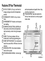
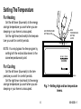
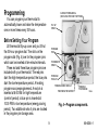
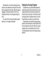
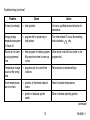
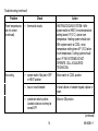
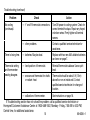
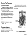
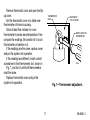
Heating/Cooling
Thermostat and Subbase
Package
T8196A/Q682A
OWNER'S MANUAL
Congratulations on your purchase of a Honeywell energy saving thermostat. The Honeywell
name is your assurance of accurate control and reliable operation for years to come.
During heating and cooling, this thermostat will automatically lower and raise the temperature
in your home one or more times every 24 hours. This allows you to significantly lower your fuel
costs, while awakening (or returning home) to a comfortable temperature.
Read this manual to learn how to use your new thermostat.
Recycling Notice
M3375
This control contains mercury in a sealed tube. Do not place control in the trash at the end of
its useful life.
If this control is replacing a control that contains mercury in a sealed tube, do not place your
old control in the trash.
Contact your local waste management authority for instructions regarding recycling and the
proper disposal of the control, or of an old control containing mercury in a sealed tube.
If you have questions, call Honeywell Inc. at 1-800-468-1502.
2
69-0636—1
Table of Contents
PAGE
Features Of Your Thermostat .......................................................................................................... 4
Setting The Temperature ................................................................................................................. 6
Inserting Timer Batteries .................................................................................................................. 7
Setting The Timer ............................................................................................................................ 8
Programming .................................................................................................................................... 9
Troubleshooting ............................................................................................................................. 12
Warranty ......................................................................................................................................... 19
3
69-0636—1
Features Of Your Thermostat
1 FLlP-UP COVER. Lift it up to set timer for
energy savings and comfort temperature
periods.
2 THERMOSTAT COVER. Lift up to show
timer.
3 THERMOMETER. Provides room temperature reading.
4 TEMPERATURE SETTING LEVERS Left
(blue mark) controls the low temperature,
right (red mark) controls the high temperature.
5 TIMER. This timer provides a 24-hour
slotted dial to hold the programming pins.
6 TIMER SETTING KNOB. Turn clockwise to
match the correct AM or PM time to the time
indicator.
7 TIME INDICATOR. Arrow head indicates
time for 24-hour dial.
8 PROGRAM INDEX WHEEL. Controls high
9
and low temperature at specific time of day
as set by program pins.
PROGRAM PINS. Must be inserted into
24-hour timer dial slots to control program
index wheel.
4
2
1
3
4
M8723
69-0636—1
5
6
10
12
11
O
B
R
W
G
Y
FAN
ON
AUTO
HEAT
OFF
COOL
M2385
9
8
7
M8722
10 PIN SLOTS. Located on 24-hour dial at
10-minute intervals for program pin
insertion.
11 MERCURY BULB AND BIMETAL ELEMENT (2). Provide automatic temperature
control by switching the heating or cooling
system on and off.
12 SUBBASE. Provides mounting base, wiring
connections and manual switching control
for heating/cooling thermostat.
5
69-0636—1
Setting The Temperature
For Heating
Set the left lever (blue mark) to the energy
savings temperature you want when you are
sleeping or your home is unoccupied.
Set the right lever(red mark)to the temperature you want for comfort periods.
HIGH
TEMPERATURE
SETTING
LEVER
LOW TEMPERATURE
SETTING LEVER
50
NOTE: You may bypass the time program by
setting both the red and blue levers to the
same temperature set point.
60
70
80
50 60 70 80
For Cooling
Set the left lever (blue mark) to the temperature you want for comfort periods.
Set the right lever (red mark) to the energy
savings temperature you want when you are
sleeping or your home is unoccupied.
M8586
Fig. 1—Setting high and low temperature
levers.
6
69-0636—1
Inserting Timer Batteries
BATTERY LOCATION FOR
(2) AAA BATTERIES;
INSTALL WITH POSITIVE
ENDS UP
Power is supplied to the timer by two AAA
alkaline batteries (not included). Install the
batteries in the thermostat as shown in Fig. 2.
Once a year or when batteries are dead,
replace with two new AAA alkaline batteries.
We recommend Energizer® batteries.
M8585
Fig. 2—Inserting timer batteries.
7
69-0636—1
Setting The Timer
Lift thermostat flip-up cover, and you’ll find
the 24-hour program dial, slotted in ten-minute
increments. Adjust the timer to the current time
by carefully turning the knob clockwise
.
DO NOT reverse the knob.
When time is correctly set, the Time Indicator Arrow (See Fig. 3) will point to the correct
time and corresponding daytime (light) or nighttime (dark) band of the program dial.
PROGRAM DIAL
PROGRAM
PIN (6)
TIMER
SETTING
KNOB
TIME
INDICATOR
ARROW
EXAMPLE: For 11 PM, the time indicator arrow
will point directly to dark band on dial. For
11 AM, the arrow will point to light band
on dial.
Daylight Savings Time
When Daylight Savings Time starts, carefully
move the knob clockwise
one hour. When
Daylight Savings Time ends, carefully move the
knob clockwise
23 hours. DO NOT
reverse the knob.
8
M821A
Fig. 3—Setting the timer.
69-0636—1
Programming
24-HOUR PROGRAM DIAL
(GRAY AREA FOR NIGHT SETTINGS)
You can program your thermostat to
automatically lower and raise the temperature
one or more times every 24 hours.
FLIP-UP
COVER
Before Setting Your Program
Lift thermostat flip-up cover and you’ll find
the 24-hour program dial. The slots on the
program dial (Fig. 4) are for the program pins
which can be inserted at ten-minute intervals.
Three red and three blue program pins are
included with your thermostat. The red pins
start the high-temperature period; the blue pins
start the low-temperature period. A heating
program was preprogrammed. A red pin is
inserted at 6:00 AM for high temperature
(comfort period); a blue pin is inserted at
10:00 PM for low temperature (energy saving
period). Two additional sets of pins are located
in the program pin storage area.
PROGRAM
PINS
THERMOSTAT
COVER
PROGRAM
PIN SLOT
PROGRAM INDEX WHEEL
TIME INDICATOR ARROW
PROGRAM
PIN STORAGE
M7348
Fig. 4—Program components.
9
69-0636—1
Setting the Heating Program
You can set up to six temperature changes
with the pins supplied. We recommend at least
five hours for each energy savings period.
To change the pins or add a new energy
savings period—
• To insert a pin, push it straight into the
selected notch on the program dial until it is
completely seated.
• To remove a pin, press against program
dial and pull the pin straight out. DO NOT
attempt to change a pin if it is engaged with
the program index wheel.
• On heating-cooling systems, you must
remove the program pins from the heating
program to set new times for your cooling
program. Write down your colors and time
for reprogramming at the next heating
season. Also, you may want to change the
temperature setting lever positions.
Decide when you want the temperature to
reach the comfort level. Find the notch on the
program dial that is one-half hour before this
time and insert a red pin. The half-hour head
start gives the furnace time to heat the house
before you wake up or arrive home.
WINTER
BEGINS
10:00 PM
ENDS
6:00 AM
DAY
BEGINS
ENERGY 7:30 AM
SAVING ENDS
PERIOD 4:00 PM
NIGHT
ENERGY
SAVING
PERIOD
1
SUMMER
1
PROGRAM
PROGRAM
TEMPERATURE PIN IN
TEMPERATURE PIN IN
°C
CONTROL
°F
°C
CONTROL
°F
14
58
27
BLUE
80
RED
68
20
RED
75
24
BLUE
58
14
BLUE
80
27
RED
68
20
RED
75
24
BLUE
NOT APPLICABLE ON HEATING-ONLY MODEL.
M8677
Fig. 5— Program examples.
10
69-0636—1
Setting the Cooling Program
Decide when you want the energy savings
period to start and insert a blue pin at the notch
that corresponds to this time. After the blue pin
engages, the furnace will be off until room
temperature drops to the energy savings set
point.
You can set both a day and night program.
See Fig. 5. for program examples.
Decide when you want the temperature to
reach the comfort level. Find the notch on the
program dial that is one-half hour before this
time and insert a blue pin. The half-hour head
start gives the air conditioner time to cool the
house before you wake up or arrive home.
Decide when you want the energy savings
period to start and insert a red pin at the notch
that corresponds to this time. After the red pin
engages, the air conditioner will be off until
room temperature rises to the energy savings
setpoint.
11
69-0636—1
Troubleshooting
Your Honeywell thermostat requires little or no attention. Most problems can generally be
traced to the following:
Problem
No heat.
Check
Action
— system switch. May be in OFF or
COOL position.
Move system switch to HEAT position.
— fuse or circuit breaker.
If blown or tripped, replace fuse or reset
breaker.
— furnace power switch. May be Off.
Move switch to ON.
— pilot flame. May be out.
Relight pilot flame per furnace manufacturers
instructions.
— R and W thermostat connections.
Turn Off power to furnace. Check for correct
terminal hookups. Repair any frayed or
broken wires. Firmly tighten all terminal
screws. Turn On power.
(continued)
12
69-0636—1
Troubleshooting (continued)
Problem
Check
Action
No heat (continued).
— other problem.
Contact a qualified service technician for
assistance.
Energy savings
temperature program
12 hours off.
— program dial for proper day or
night phase.
Turn timer ahead 12 hours. Move setting
knob clockwise
only.
Rooms do not warm
up at programmed
time.
— timer program for heating system.
May need more time to warm up
rooms.
Move red pin one-half hour earlier on the
program dial.
Temperature change
occurs at the wrong
time.
— programs pins for correct time
locations.
Relocate pins to desired settings.
Room temperatures
are not correct.
— positions of thermostat setpoint
levers.
Reset to desired temperatures.
— position of subbase system
switch.
Move to desired operating position.
(continued)
13
69-0636—1
Troubleshooting (continued)
Problem
Check
Action
Room temperatures
are not correct
(continued).
— thermostat circuits.
HEATING/COOLING SYSTEM—With
system switch at HEAT, move temperature
setting levers 5°F (3°C) above room
temperature. Heating system should start.
With system switch at COOL, move
temperature setting levers 5°F (3°C) below
room temperature. Cooling system should
start. IF THE SYSTEMS DO NOT
OPERATE, CALL A QUALIFIED
TECHNICIAN.
No cooling.
— system switch. May be in OFF
or HEAT position.
Move switch to COOL position.
— fuse or circuit breaker.
If fuse is blown or breaker tripped, replace or
reset.
— condenser switch position.
Located outdoors and may be
turned OFF.
Move to ON position.
(continued)
14
69-0636—1
Troubleshooting (continued)
Problem
Check
Action
— Y and R thermostat connections.
Turn Off power to cooling system. Check for
correct terminal hookups. Repair any frayed
or broken wires. Firmly tighten all terminal
screws.
— other problems.
Contact a qualified service technician for
assistance.
Timer is losing time.
— batteries. May be dead.
Replace with two new AAA alkaline batteries
as shown on page 7.
Thermostat setting
and thermometer
reading disagree.
— level position of thermostat.
— area around thermostat for drafts
or radiant heat.
Reinstall thermostat subbase. Use a spirit
level.
Thermostat should be about 5 ft (1.5m)
above floor on an inside wall. Contact
qualified service technician for change of
location.
— calibration of thermometer.
See instructions on page 16.
No cooling
(continued).
If Troubleshooting section has not solved the problem, call a qualified service technician or
Honeywell Customer Assistance Center at 1-800-468-1502, Monday - Friday, 7:00 AM to 5:30 PM,
Central time, for additional assistance.
15
69-0636—1
Servicing The Thermostat
If the set point lever and the thermometer
reading do not agree, follow the procedure on
the next page.
Cycle Rate Adjustment
The equipment should cycle on and off just
enough to keep the room temperature close to
the temperature lever settings.
If the thermostat seems to cycle the heating
system too fast or too slow, adjust the cycle
rate by moving the anticipator setting lever one
indicator mark at a time (Fig. 6). Observe the
heating system operation after each adjustment.
ANTICIPATOR
SCALEPLATE
NOTE: Most hot water systems require a
setting of 1.2A.
ANTICIPATOR
SETTING LEVER
Thermometer Adjustment
The thermometer has been accurately
calibrated at the factory and should only need
adjustment if it was mishandled.
M7317
Fig. 6—Heat anticipator setting.
16
69-0636—1
Remove thermostat cover and open the flipup cover.
Set the thermostat cover on a table near
thermometer of known accuracy.
Allow at least five minutes for cover
thermometer to sense area temperature, then
compare the readings. Be careful not to touch
thermometer or breathe on it.
If the readings are the same, replace cover
and put the system into operation.
If the readings are different, insert a small
screwdriver in the thermometer slot, shown in
Fig. 7, and turn it until both thermometers
read the same.
Replace thermostat cover and put the
system into operation.
THERMOMETER
SLOT
BACKSIDE OF
FLIP-UP COVER
INSERT AND TURN
SCREWDRIVER
M1810
Fig. 7—Thermometer adjustment.
17
69-0636—1
If you have questions regarding the installation and programming of your Honeywell thermostat, please contact the Honeywell Customer Assistance Center at 1-800-468-1502, Monday Friday, 7:00 AM to 5:30 PM, Central time. Before you call, please have the following information
available: make and model of furnace, thermostat, and air conditioner.
18
69-0636—1
Limited One-Year Warranty
Honeywell warrants this product to be free from defects in the workmanship or materials, under normal use and service, for a period of one (1)
year from the date of purchase by the consumer. If, at any time during the warranty period, the product is detective or malfunctions, Honeywell shall
repair or replace it (at Honeywell’s option) within a reasonable period of time.
If the product is detective,
(I) return it, with a bill of sale or other dated proof-of-purchase, to the dealer or contractor from which you purchased it, or
(ii) package it carefully, along with proof-of-purchase (including date of purchase) and a short description of the malfunction,
and mail it, postage prepaid, to the following address:
Honeywell Inc.
Return Goods Department
1050 Berkshire Lane
Plymouth, MN 55441-4437
This warranty does not cover removal or reinstallation costs. This warranty shall not apply if it is shown by Honeywell that the defect or
malfunction was caused by damage which occurred while the product was in the possession of a consumer.
Honeywell’s sole responsibility shall be to repair or replace the product within the terms stated above. HONEYWELL SHALL NOT BE LIABLE
FOR ANY LOSS OR DAMAGE OF ANY KIND, INCLUDING ANY INCIDENTAL OR Consequential DAMAGES RESULTING, DIRECTLY OR
INDIRECTLY FROM ANY BREACH OF ANY WARRANTY, EXPRESS OR IMPLIED, OR ANY OTHER FAILURE OF THIS PRODUCT. Some
states do not allow the exclusion or limitation of incidental or consequential damages, so this limitation may not apply to you.
THIS WARRANTY IS THE ONLY EXPRESS WARRANTY HONEYWELL MAKES ON THIS PRODUCT. THE DURATION OF ANY IMPLIED
WARRANTIES, INCLUDING THE WARRANTIES OF MERCHANTABILITY AND FITNESS FOR A PARTICULAR PURPOSE, IS HEREBY LIMITED
TO THE ONE YEAR DURATION OF THIS WARRANTY. Some states do not allow limitations on how long an implied warranty lasts, so the above
limitation may not apply to you.
This warranty gives you specific legal rights, and you may have other rights which vary from state to state.
If you have questions concerning this warranty, please write our Customer Assistance Center, Honeywell Inc.., P.O. Box 524, Minneapolis, MN
55440-0524 or call 1-800-468-1502, Monday - Friday, 7:00 a.m. to 5:30 p.m., Central time.
19
69-0636—1
Automation and Control Solutions
Honeywell International Inc. Honeywell Limited—Honeywell Limitée
1985 Douglas Drive North
35 Dynamic Drive
Golden Valley, MN 55422
Scarborough, Ontario M1V 4Z9
D.F. ©Honeywell Inc. 1994 Rev. 11-94 Form Number 69-0636—1