1
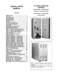
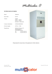
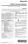
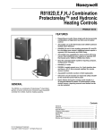
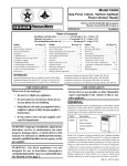
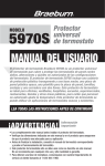
R8184G PROTECTORELAY
OIL PRIMARY
APPLICATION
HOLE OR KNOCKOUT FOR
CAD CELL LEADS
RED RESET
BUTTON
The TRADELINE intermittent ignition oil primary control
operates the oil burner, oil valve (if desired) and the ignition
transformer in response to a call for heat from the thermostat. Through a C554 Cad Cell Flame Sensor, the R8184
monitors the burner flame and shuts down the system on
ignition failure or on flame failure during the run cycle. A light
emitting diode (LED) on the terminal strip lights when the
safety switch opens to provide safety shutdown indication.
A manual reset button is provided to reset the safety switch
after lockout.
For convenience in system maintenance, the safety
switch can be manually opened using a lever on the front of
the control. Clock thermostats that power the clock through
the primary control transformer will lose time during lockout
unless backup batteries are installed.
R8184G is component recognized by Underwriters Laboratories Inc. and meets their flammability test requirements
for a final enclosure.
LOW VOLTAGE
TERMINAL STRIP
2
4 x 4 JUNCTION
BOX
CAD
CELL LEADS
LINE
VOLTAGE LEADS
MOUNTING
SCREW HOLE
1
1 STRIP WIRES 3/8 in. (9.5 mm); INSERT FROM SIDE, ABOVE OR BELOW.
2 T-T TERMINALS ON R8184G; T1-T2 TERMINALS ON R8184N.
Fig. 1—Mounting the R8184G controls with 130° F
[54° C] maximum ambient temprature.
INSTALLATION
WHEN INSTALLING THIS PRODUCT…
1. Read these instructions carefully. Failure to follow
them could damage the product or cause a hazardous
condition.
2. Check the ratings given in the instructions and on the
product to make sure the product is suitable for your
application.
3. Installer must be a trained, experienced service technician.
4. After installation is complete, check out product operation as provided in these instructions.
LOCATION
1. Mount on a 4 x 4 inch junction box, directly on the main
burner, or inside the appliance cabinet. In replacement
applications, mount in the same location as the old control.
2. Ensure the operating temperatures are within the ambient temperature range. Ambient temperature ranges are
either -40° to 130° F [-40° C to 54° C] or -40° F to 150° F
[-40° C to 66° C] (Refer to box label).
MAKE WIRING CONNECTIONS AND MOUNT CONTROL
Wiring must comply with all local codes and ordinances.
Before mounting the control, make line voltage connections as shown in Fig. 1 or 2. Splice leads with solderless
connectors. Do not exceed load ratings shown on the device
label.
If cad cell leads are run with line voltage wires, breakout
knockout at the bottom of the low voltage terminal strip and
thread can cell leads through the hole.
If necessary use control as a template to mark and drill new
mounting holes. Mount using No. 6 screws (obtain locally).
CAUTION
1. Disconnect power before beginning installation to
prevent electrical shock or equipment damage.
2. Make sure combustion chamber is free of oil or
vapor before starting system.
JUNCTION BOX
R8184G PROTECTORELAY CONTROL
THERMOSTAT
LINE VOLTAGE
THERMOSTAT
BLACK
T
2
2
SAFETY
SWITCH
1K
T
LIMIT
SAFETY
SWITCH
HEATER
LOCKOUT
INDICATOR
LED
R1
SAFETY
SWITCH
1K2
TRIAC
L1
(HOT)
1
ORANGE
BILATERAL
SWITCH
CAD CELL
F
M1643B
BURNER
MOTOR
L2
OIL VALVE
(OPTIONAL)
1K1
R2
IGNITION
CAPACITOR
F
WHITE
1 POWER SUPPLY. PROVIDE DISCONNECT MEANS AND OVERLOAD PROTECTION AS REQUIRED.
2 TO USE R8184 WITH LINE VOLTAGE CONTROLLER, JUMPER T-T TERMINALS AND CONNECT LINE VOLTAGE THERMOSTAT IN
SERIES WITH LIMIT CONTROLLER.
M1635
Fig. 2—Typical hookup for TRADELINE R8184G with indicator light.
D.T.
Rev. 4-91
Form Number 69-0617—1
© Honeywell Inc. 1991
L1 (HOT)
FAN
RELAY
1
L2
T87F/Q539A
COOLING
TRANSFORMER
RC
COOLING
CONTROL
G
Y
RH
JUNCTION BOX
R8184G PROTECTORELAY CONTROL
LINE VOLTAGE
THERMOSTAT
W
BLACK
T(R)
X
2
2
SAFETY
SWITCH
1K
T(W)
LIMIT
3
VIOLET
R1
LOCKOUT
INDICATOR
LED
SAFETY
SWITCH
SAFETY
SWITCH
HEATER
1
ORANGE
BILATERAL
SWITCH
TRIAC
CAD CELL
F
1K2
L1
(HOT)
BURNER
MOTOR
L2
OIL VALVE
(OPTIONAL)
1K1
R2
IGNITION
CAPACITOR
WHITE
F
1 POWER SUPPLY. PROVIDE DISCONNECT MEANS AND OVERLOAD PROTECTION AS REQUIRED.
2 TO USE R8184 WITH LINE VOLTAGE CONTROLLER, JUMPER T-T TERMINALS AND CONNECT LINE
VOLTAGE THERMOSTAT IN SERIES WITH LIMIT CONTROLLER.
3 REMOVE PLUG AND ROUTE VIOLET LEADWIRE THROUGH HOLE IN BASE OF R8184.
M718
Fig. 3—Typical hookup for Tradeline R8184G with indicator light and isolated alarm relay.
2. Safety switch should lock out in safety switch timing
(see label). Indicator light should come on. Ignition and
motor should stop and oil valve should close.
Simulate power failure:
1. Follow starting procedure to turn on burner.
2. With burner running, trip circuit breaker or remove
fuse to turn off power to the system.
3. Burner should stop.
4. Restore power. Burner should restart.
If system does not operate as described, proceed to
Troubleshooting.
Mount control as shown in Fig. 1 or 2. After mounting,
make low voltage connections to the screw terminals. Strip
leads 3/8 in. [10 mm] and insert under terminal screw. See
Fig. 1 or 2. Connect cad cell leads to F-F terminals and
thermostat leads to T-T terminals. See Fig. 3 or 4.
CHECKOUT
START SYSTEM
WARNING
TROUBLESHOOTING AND
MAINTENANCE
Fire hazard.
Can cause severe burns.
Make sure combustion chamber is free of oil or oil
vapor before starting system.
1. Push in and release red reset button.
2. Open hand valve in oil supply line.
3. Make sure system is powered. Check circuit
breaker or fuse and close system switch, if
provided.
4. Set thermostat to call for heat.
5. Burner should light and operate until call for
heat ends.
PRELIMINARY STEPS
1. Check wiring connections and power supply. Make
sure power is on to the controls, burner motor, and ignition
transformer.
2. Make sure limit control is closed.
CHECK SAFETY FEATURES
Simulate flame failure:
1. Follow starting procedure to turn on burner.
2. Close hand valve in oil supply line.
3. Safety switch should lock out approximately in safety
switch timing indicated on label. Indicator light should come
on. Ignition and motor should stop and oil valve should
close.
Simulate ignition failure:
1. Follow starting procedure to turn on burner, except do
not open oil supply hand valve.
CHECK OIL PRIMARY RELAY
NOTE: You’ll need an insulated jumper wire with both ends
stripped.
1. Disconnect cad cell leads from F-F terminals.
2. Reset safety switch and set thermostat to call for heat.
Burner should start.
3. Within safety switch timing, jumper F-F terminals with
insulated jumper wire. Burner should continue to run.
4. After safety switch timing, remove jumper. Burner
should shut down in safety switch timing.
5. If operation is not as described, replace oil primary
control.
IMPORTANT
This control contains no field-serviceable parts. Do
not attempt to take it apart. Replace entire control if
operation is not as described.
2
CHECK CAD CELL
1. Disconnect power at system switch, circuit breaker or
fuse.
2. Clean cell face with soft cloth.
3. Make sure cell is seated securely in socket. Be careful
not to disturb socket position.
4. Reconnect cad cell leads to F-F terminals.
5. Reset safety switch, turn on power and set thermostat
PUSH LEVER DOWN
TO TRIP SAFETY SWITCH
WHEN SAFETY SWITCH TRIPS
RESET BUTTON POPS OUT
INDICATOR LIGHT COMES ON
(TRADELINE ONLY)
TRIP SAFETY SWITCH BEFORE PERFORMING
BURNER MAINTENANCE
CAUTION
Tripping the safety switch shuts down the burner but
does not disconnect the power supply. Turn off power
at system switch or circuit breaker before servicing
the control system, burner motor, oil valve or ignition
to avoid electric shock.
M17882
To trip the safety switch, move the safety switch lever
down until the red reset button pops out and the indicator
light comes on. See Fig. 5. Burner will not operate until
safety switch is reset by pushing in the red reset button.
Fig. 4—Move lever down to trip safety switch.
3
69-0617—1
Automation and Control Solutions
Honeywell International Inc. Honeywell Limited—Honeywell Limitée
1985 Douglas Drive North
35 Dynamic Drive
Golden Valley, MN 55422
Scarborough, Ontario M1V 4Z9
www.honeywell.com