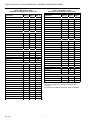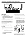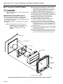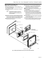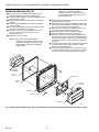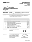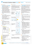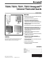
1
TG509, TG510, TG511, TG512 Versaguard™
Universal Thermostat Guards
PRODUCT DATA
FEATURES
❥ Available in four sizes: mini, small, medium and large,
to fit virtually all thermostats.
❥ Used in both new and existing applications.
❥ Constructed of smoke-colored transparent
polycarbonate, off-white opaque polycarbonate,
opaque plastic, clear plastic or off-white painted steel.
TG509
TG510A
❥ Opaque plastic guards match commercial interior
decorating schemes.
❥ Can be mounted on the wall or an exposed junction box.
❥ Smoke-colored transparent or off-white opaque
polycarbonate ring base without wallplate, or opaque
plastic wallplate and plastic ring base. All models
include a guard cover, tumbler lock, two keys and a
Honeywell logo insert.
❥ TG509F,G models permit thermostat calibration
without ring base removal.
TG511D
TG512B
❥ Provision for Honeywell logo (included with all models)
or OEM logo on guard cover.
GENERAL
❥ Ideal for office areas, lobbies, supermarkets,
restaurants, clinics, hospitals, convenience stores,
and similar applications.
The Versaguard™ Universal Thermostat Guards cover wall
thermostats and protect against tampering, damage and
unauthorized adjustment of thermostat settings.
❥ Tamper-resistant lock; key can be removed only when
in the locked position.
❥ Vertical or horizontal mount.
❥ Guard base vents allow airflow for optimum
thermostat performance.
CONTENTS
General ...............................................................................
Features ..............................................................................
Specifications ......................................................................
Ordering Information ...........................................................
Installation ...........................................................................
Checkout .............................................................................
® U.S. Registered Trademark
Copyright © 1996 Honeywell Inc. • All Rights Reserved
1
1
2
2
6
11
68-0104-4
TG509, TG510, TG511, TG512 VERSAGUARD™ UNIVERSAL THERMOSTAT GUARDS
TG510A, TG511A, TG512A Versaguard™ Universal
Thermostat Guards: clear plastic cover, opaque plastic
wallplate and clear plastic ring mounting base.
TG510B, TG511B, TG512B Versaguard™ Universal
Thermostat Guards: opaque plastic cover, opaque plastic
wallplate and opaque plastic ring mounting base.
SPECIFICATIONS
IMPORTANT
The specifications listed in this publication do not
include normal manufacturing tolerances. Therefore,
this unit may not exactly match the listed specifications.
Also, this product is tested and calibrated under closely
controlled conditions, and some minor differences in
performance can be expected if those conditions are
changed. For exact engineering specifications, contact
your Honeywell representative.
Standard Models:
TG510D, TG511D, TG512D Versaguard™ Universal
Thermostat Guards: painted steel cover (off-white), opaque
plastic wallplate and opaque plastic ring mounting base.
Additional Features:
TRADELINE® and Standard Versaguard™ Universal
Thermostat Guards include Honeywell logo insert (fieldinstalled), mounting template, screws, anchors and tumbler
lock with two keys.
TRADELINE® Models:
TRADELINE® models are selected and packaged for ease of
stocking, ease of handling, and maximum replacement value.
TRADELINE® Models Available:
TG509F Versaguard™ Universal Thermostat Guard:
transparent polycarbonate cover (smoke tint) ring base
and allen wrench.
TG509G Versaguard™ Universal Thermostat Guard:
opaque polycarbonate cover (off-white) ring base and
allen wrench.
See Tables 1 and 2 for thermostat guard applications.
Accessory:
191990A Replacement Keys (2); can also be used with
TG500 and TG502 Thermostat Guards.
ORDERING INFORMATION
When purchasing replacement and modernization products from your TRADELINE® wholesaler or your distributor, refer to the
TRADELINE® Catalog or price sheets for complete ordering number, or specify:
1. Order number.
2. Transparent (smoke tint) or opaque (off-white) polycarbonate (TG509 models only), clear or opaque plastic, or painted
steel cover (off-white).
3. Accessory.
If you have additional questions, need further information, or would like to comment on our products or services, please write or phone:
1. Your local Honeywell Home and Building Control Sales Office (check white pages of phone directory).
2. Home and Building Control Customer Relations
Honeywell, 1885 Douglas Drive North
Minneapolis, Minnesota 55422-4386
In Canada—Honeywell Limited/Honeywell Limitee, 35 Dynamic Drive, Scarborough, Ontario M1V 4Z9. International Sales and
Service Offices in all principal cities of the world. Manufacturing in Australia, Canada, Finland, France, Germany, Japan, Mexico,
Netherlands, Spain, Taiwan, United Kingdom, U.S.A.
68-0104—4
2
TG509, TG510, TG511, TG512 VERSAGUARD™ UNIVERSAL THERMOSTAT GUARDS
Table 1. TG509 Thermostat Guard Applications.
Thermostat
HONEYWELL
TP970
TP971
TP972
TP973
TP974
T7660
TP9600 Series
JOHNSON
T4002
T4100
T4506
T4756
T5002
POWERS
TH192
TH193
TH194
TT184
ROBERTSHAW
Table 2. TG510, TG511, TG512
Thermostat Guard Applications.
TG509 (Fig. 1)
Thermostat
HONEYWELL
T87/Q539
●
●
●
●
●
●
●
T451
T498
T631
T641
T651
T694
T810
T822
T834
T841
T874/Q674
T4039
T6051A
T6052
T7047
T8034
T42
T92
T921
T7200
T7300/Q7300
T7400
T8082/Q682
T8085/Q682
T8090/Q682
T8195/Q682
T8600
T8601
T8602
T8603
T8611
T8621
T8624
T8631
TP970
W884
Y594
●
●
●
●
●
●
●
●
●
Original
T12
T13
T18
T19
T23
T27
T32
T33
T34
T35
Uniline
2211
2212
2214
2216
2218
●
●
●
●
●
●
●
●
●
●
●
●
●
●
●
3
TG510
(Fig. 2)
●
TG511
(Fig. 3)
a
TG512
(Fig. 4)
●
●
●
●
●
●
●
●
●
●
●
●
●
●
●
●
●
c
b
b
a
●
●
●
●
●
●
●
●
●
●
●
●
●
●
●
●
●
●
●
●
●
68-0104—4
TG509, TG510, TG511, TG512 VERSAGUARD™ UNIVERSAL THERMOSTAT GUARDS
Table 2. TG510, TG511, TG512
Thermostat Guard Applications (Continued).
Table 2. TG510, TG511, TG512
Thermostat Guard Applications (Continued).
Thermostat
ITT GENERAL
T199
T80
T90
T91
T330 SERIES
T340 SERIES
ENERSTAT
DSP100—DSP700
ET52
HC-7
HP-1
K3-WN
K4-W
MS-1N
HP-2
ROBERTSHAW
TX400
500 SERIES
300-610
300-620
300-630
300-642
WHITE RODGERS
1C-30
1C-31
1C-70
1D-30
1D-35
1D-36
1E-30
1E-31
1E-35
1E-36
1E-56
1F-30
1F-56
1F-57
1F-58
1F-60
1F-62
1F-70
68-0104—4
TG510
(Fig. 2)
TG511
(Fig. 3)
TG512
(Fig. 4)
TG510
TG511
TG512
Thermostat
(Fig. 2) (Fig. 3) (Fig. 4)
WHITE RODGERS
1F-72
●
1F-75
●
1F-76
●
1F-90
●
1F-91
●
1F-92
●
1F-93
●
1F-94
●
1F-95
●
1F-97
●
AMERICAN STABILIS
R-90
●
R-100
●
R-105
●
R-106
●
HP-1
●
HP-10
●
HP15/20/22
●
HP100
●
HP150/200/220
●
HP1000
●
HP1500/2000/3000
●
HP2001
●
SIMPLESTAT
●
COLUMBUS ELECTRIC
RSH-420A
●
RSV-420
●
HPC SERIES
●
SECO
TA-2000
●
TM-1000
●
TM-1400
●
a Use TG512 for thermostat wallplate with dealer logo.
b Turn TG511 90 degrees to fit thermostat wallplate with
dealer logo.
c Fits T87F The Round® Thermostat with decorator wallplate.
●
●
●
●
●
●
●
●
●
●
●
●
●
●
●
●
●
●
●
●
●
●
●
●
●
●
●
●
●
●
●
●
●
●
●
●
●
●
4
TG509, TG510, TG511, TG512 VERSAGUARD™ UNIVERSAL THERMOSTAT GUARDS
RING BASE ONLY
FRONT VIEW
SIDE VIEW
D
C
F
B
A
E
A
B
MODEL
IN.
MM
IN.
MM
NUMBER
TG510A 2-1/2 64 2-7/8
73
C
IN.
4
G
D
MM
IN.
102 4-5/8
E
MM
117
IN.
3-5/8
F
MM
92
G
IN. MM
IN. MM
5-1/2 140 2-1/8 54
M15015
Fig. 1. TG509 overall dimensions.
RING BASE ONLY
FRONT VIEW
SIDE VIEW
F
D
C
B
A
E
MODEL
A
B
NUMBER
IN.
MM
IN.
MM
TG510A 4-7/16 113 3-1/2
89
TG510B 4-7/16 113 3-1/2
89
TG510D 4-7/16 113 3-1/2
89
C
IN.
3-1/2
3-1/2
3-1/2
G
E
F
G
MM
IN. MM
IN..
89 4-7/16 113 5-7/8
89 4-7/16 113 5-7/8
89 4-7/16 113 5-11/16
D
MM
IN.
149 5-7/8
149 5-7/8
144 5-11/16
IN.
MM
149 2-1/2
149 2-1/2
144 2-7/16
MM
64
64
62
M642C
Fig. 2. TG510 overall dimensions.
RING BASE ONLY
C
SIDE VIEW
FRONT VIEW
D
F
B
A
E
MODEL
A
B
NUMBER
IN.
MM
IN.
TG511A 6-1/16 154 5-1/8
TG511B 6-1/16 154 5-1/8
TG511D 6-1/16 154 5-1/8
C
MM
IN.
130 4-1/8
130 4-1/8
130 4-1/8
D
MM
105
105
105
IN.
5-1/16
5-1/16
5-1/16
G
E
F
G
MM
IN. MM
IN. MM
IN.
MM
129 7-1/2 191 6-1/2 165 2-15/16 75
129 7-1/2 191 6-1/2 165 2-15/16 75
129 7-3/8 187 6-3/8 162 2-7/8
73
M643C
Fig. 3. TG511 overall dimensions.
5
68-0104—4
TG509, TG510, TG511, TG512 VERSAGUARD™ UNIVERSAL THERMOSTAT GUARDS
RING BASE ONLY
SIDE VIEW
FRONT VIEW
D
C
F
B
E
A
A
MODEL
IN.
NUMBER
TG512A
8-3/8
TG512B
8-3/8
TG512D 8-3/8
B
MM IN.
213 7-3/8
213 7-3/8
213 7-3/8
D
C
IN.
MM
187 4-7/8
187 4-7/8
187 4-7/8
MM
124
124
124
IN.
5-7/8
5-7/8
5-7/8
G
F
E
MM
149
149
149
IN.
9-3/4
9-3/4
9-5/8
MM
IN.
248 7-1/4
248 7-1/4
244 7-1/8
G
MM IN. MM
184 3-3/8 86
184 3-3/8 86
180 3-1/4 83
M644C
Fig. 4. TG512 overall dimensions.
쐄 Mount the guard cover by placing the hinged edge of
the guard cover on the ring base and swinging it down
(horizontal mounting) or to the side (vertical mounting)
until the guard cover is in place against the ring base.
See Fig. 7.
쐂 Lock the thermostat guard by turning the key (provided)
counterclockwise. See Fig. 8. The key can be removed
only in the locked position.
쐆 Remove the paper backing and clear protective cover
from the included monogram and place the monogram
in the recessed area on the guard cover. See Fig. 9.
INSTALLATION
When Installing this Product…
1. Read these instructions carefully. Failure to follow them
could damage the product.
2. Check the dimensions given in the instructions and on
the product to make sure the product is suitable for your
application.
The Versaguard™ Universal Thermostat Guards can be used
in new or existing thermostat applications. In existing
thermostat applications, the guard can be installed without
removing the thermostat from the wall. In these applications,
the thermostat guard is used without the solid wallplate (only
ring base and cover are used). In new thermostat
applications, the guard can be used with or without the solid
wallplate. The wallplate is typically used to cover mounting
marks from the old thermostat.
NOTE: The TG509F,G Thermostat Versaguards™ are
shipped with an allen wrench secured in the
top notch of the ring base. When thermostat
calibration is needed, remove the Versaguard
cover and use the wrench to remove the top
two allen screws in the thermostat cover. This
allows servicing of the thermostat while the
ring base is in place.
MOUNTING RING BASE
Refer to the following sections for specific mounting
procedures for thermostat guard applications.
FRONT OF DEVICE
COVER
WALL
Mount Thermostat Guard Without Wallplate
(Fig. 5 and 6)
MOUNTING
HOLES (4)
THERMOSTAT
쐃 Place the ring base over the thermostat (and wallplate,
subbase or adaptor plate) on the wall.
쐇 Align the ring base with the thermostat and level
approximately.
쐋 Mark the four mounting holes.
NOTE:
90
80
70
60
90
80
70
60
Do not use the four brass screws for mounting
the TG509. The brass screws are intended for
models with wallplates only.
RING BASE
KEY
RECESSED AREA
FOR MONOGRAM
쐏 Mount the ring base on the wall using the four no. 6
sheet metal screws and four anchors provided as
shown in Fig. 5 for the TG509 and Fig. 6 for the FG510,
TG511 and TG512.
68-0104—4
RING
BASE
MOUNTING SCREWS (4)
M15014
Fig. 5. Mount TG509 ring base only in existing thermostat
applications. TG509 guard cover, lock, monogram area.
6
TG509, TG510, TG511, TG512 VERSAGUARD™ UNIVERSAL THERMOSTAT GUARDS
COVER
WALL
THERMOSTAT
C
50
HE
AT
50
60
70
60
70
L
OO
80
80
50
60
70
80
MOUNTING
HOLES (4)
RING BASE
RING BASE
KEY
MOUNTING SCREWS (4)
M653B
M655
Fig. 8. Lock thermostat guard
(TG510, TG511, TG512 shown).
Fig. 6. Mount TG510, TG511 and TG512 ring bases only in
existing thermostat applications.
MONOGRAM
RING BASE
REMOVE
CLEAR
PROTECTIVE
COVER
REMOVE
PAPER
BACKING
COVER
M654A
Fig. 7. Mount guard cover (TG510, TG511, TG512 shown).
1
PLACE MONOGRAM
IN RECESSED AREA
ON GUARD COVER
1 TURN MONOGRAM 90 DEGREES
ON VERTICALLY MOUNTED GUARDS.
M656A
Fig. 9. Apply monogram to thermostat guard
(TG510, TG511, TG512 shown).
7
68-0104—4
TG509, TG510, TG511, TG512 VERSAGUARD™ UNIVERSAL THERMOSTAT GUARDS
쐏 Mount the thermostat subbase (or wallplate) and the
guard wallplate to the wall using the 1-1/4 in. sheet
metal screws provided with the thermostat. The guard
wallplate must be placed between the thermostat
subbase (or wallplate) and the wall. See Fig. 10.
쐄 Wire the thermostat subbase (or wallplate). Refer to the
installation instructions provided with the thermostat.
쐂 Mount the thermostat on the subbase (or wallplate) and
place the thermostat cover on the thermostat.
쐆 Mount the guard ring base over the thermostat,
subbase (wallplate) and guard wallplate.
쐊 Attach the ring base using four no. 6 sheet metal
screws or four anchors and screws (provided).
쐎 Mount the guard cover by placing the hinged edge of
the guard cover on the ring base and swinging it down
(horizontal mounting) or to the side (vertical mounting)
until the thermostat guard is in place against the ring
base. See Fig. 7.
쐅 Lock the thermostat guard by turning the key (provided)
counterclockwise. See Fig. 8. The key can be removed
only in the locked position.
쐈 Remove the paper backing and clear protective cover
from the included monogram and place the monogram
in the recessed area on the guard cover. See Fig. 9.
Mount Thermostat Guard With Wallplate
CAUTION
Disconnect power supply to prevent electrical shock or
equipment damage.
Wall Mounting Front-wired Subbase (Fig. 10)
쐃 Place the thermostat subbase (or wallplate) on the
wallplate template and mark the mounting holes.
쐇 Locate the mounting holes on the guard wallplate using
the template as a guide.
쐋 Drill the required 5/32 in. mounting holes in the guard
wallplate.
NOTE: If the mounting hole pattern on the guard
wallplate does not match the pattern on the
thermostat subbase or wallplate, drill
additional mounting holes in the guard
wallplate.
WALL
GUARD WALLPLATE
SUBBASE
THERMOSTAT
OL
CO
50
T
EA
50
60
70
60
70
80
80
H
50
60
70
80
MOUNTING
HOLES (4)
RING BASE
MOUNTING SCREWS (4)
M657B
Fig. 10. Mount guard wallplate and ring base on thermostat with front-wired subbase or wallplate.
68-0104—4
8
TG509, TG510, TG511, TG512 VERSAGUARD™ UNIVERSAL THERMOSTAT GUARDS
쐂 Mount the thermostat and the guard wallplate to the
wall using the 1-1/4 in. sheet metal screws provided
with the thermostat. Make sure the guard wallplate is
placed between the thermostat and the wall.
쐆 Place the thermostat cover on the thermostat.
쐊 Mount the guard ring base over the thermostat and the
guard wallplate.
쐎 Attach the ring base using four 1-1/4 in. sheet metal
screws or four anchors and screws (provided).
쐅 Mount the guard cover by placing the hinged edge of
the guard cover on the ring base and swinging it down
(horizontal mounting) or to the side (vertical mounting)
until the guard cover snaps into place against the ring
base. See Fig. 7.
쐈 Lock the thermostat guard by turning the key (provided)
counterclockwise. See Fig. 8. The key can be removed
only in the locked position.
쐉 Remove the paper backing and clear protective cover
from the included monogram and place the monogram
in the recessed area on the guard cover. See Fig. 9.
Back-wired Thermostat (Fig. 11)
쐃 Place the thermostat on the wallplate template and
mark the mounting holes.
쐇 Locate the mounting holes on the guard wallplate using
the template as a guide.
쐋 Drill the required 5/32 in. mounting holes in the guard
wallplate.
NOTE:
If the mounting hole pattern on the guard
wallplate does not match the pattern on the
thermostat, drill additional mounting holes in
the guard wallplate.
쐏 Mount the smooth side of the guard wallplate facing the
thermostat and run the system wires through the wiring
hole in the guard wallplate. The guard wallplate must be
placed between the thermostat and the wall. See Fig. 11.
쐄 Back-wire the thermostat. Refer to the instructions
provided with the thermostat.
WALL
GUARD WALLPLATE
THERMOSTAT
BASE
CONNECT WIRES
TO TERMINALS ON
BACK OF THERMOSTAT BASE
THERMOSTAT COVER
RM
WA
80
70
60
50
OL
CO
MOUNTING
HOLES (4)
RING BASE
MOUNTING SCREWS (4)
M658A
Fig. 11. Mount guard wallplate and ring base on back-wired thermostat.
9
68-0104—4
TG509, TG510, TG511, TG512 VERSAGUARD™ UNIVERSAL THERMOSTAT GUARDS
When using a back-wired subbase
(wallplate), run the system wires from the
junction box through the wiring hole in the
guard wallplate only.
Junction Box Mounting (Fig. 12)
쐃 Place the thermostat subbase (or wallplate) on the
wallplate template and mark the mounting holes.
쐇 Locate the mounting holes on the guard wallplate using
the template as a guide.
쐋 Drill the required 5/32 in. mounting holes in the guard
wallplate.
쐏 Secure the guard wallplate to the ring base using the
screws provided.
쐄 Place the guard wallplate (with smooth side facing the
ring base) on the back of the ring base.
쐂 Insert the securing screws through the holes on the
front of the ring base and into the posts on the
wallplate. See Fig. 12.
쐆 Tighten the screws securely.
쐊 Wire the back-wired subbase. Refer to the instructions
provided with the thermostat.
쐎 Mount the thermostat subbase (wallplate) and the ring
base with the guard wallplate to the junction box using
the 1-1/4 in. sheet metal screws provided.
쐅 Wire the front-wired subbase (wallplate). Refer to the
instructions provided with the thermostat.
쐈 Mount the thermostat on the subbase (wallplate).
쐉 Place the thermostat cover on the thermostat.
씈 Mount the guard cover by placing the hinged edge of
the guard cover on the ring base and swinging it down
(horizontal mounting) or to the side (vertical mounting)
until the guard cover is in place against the ring base.
See Fig. 7.
씉 Lock the thermostat guard by turning the key (provided)
counterclockwise. See Fig. 8. The key can only be
removed in the locked position.
씊 Remove the paper backing and clear protective cover
from the included monogram and place the monogram
in the recessed area on the guard cover. See Fig. 9.
NOTES: When using a front-wired subbase
(wallplate), run the system wires from the
junction box through the wiring hole in the
guard wallplate and subbase (wallplate)
cable opening.
HORIZONTAL
OUTLET BOX
GUARD
WALLPLATE
SUBBASE
WALLPLATE
POSTS
MOUNTING
SCREWS (2)
OL
CO
50
RING BASE
AT
HE
SECURING SCREWS (4)
50
60
70
60
70
80
80
50
60
70
80
THERMOSTAT
M1638A
Fig. 12. Mount guard wallplate with ring base and thermostat on junction box (front-wired thermostat subbase shown).
68-0104—4
10
TG509, TG510, TG511, TG512 VERSAGUARD™ UNIVERSAL THERMOSTAT GUARDS
Remove Thermostat Guard
COVER
쐃 Remove the thermostat guard cover by inserting the
key and turning the key clockwise until the locking
mechanism is disengaged.
쐇 Remove the guard cover by swinging it out away from
the ring base and lifting it off. See Fig. 13.
CHECKOUT
Before leaving the installation, refer to the applicable
instructions to check the operation of the thermostat or
subbase.
RING BASE
KEY
M659
Fig. 13. Remove thermostat guard cover
(TG510, TG511, TG512 shown).
11
68-0104—4
TG509, TG510, TG511, TG512 VERSAGUARD™ UNIVERSAL THERMOSTAT GUARDS
Home and Building Control
Honeywell Inc.
Honeywell Plaza
P.O. Box 524
Minneapolis MN 55408-0524
Home and Building Control
Honeywell Limited-Honeywell Limitée
155 Gordon Baker Road
North York, Ontario
M2H 2C9
Honeywell Latin American Division
Miami Lakes Headquarters
14505 Commerce Way Suite 500
Miami Lakes FL 33016
Honeywell Europe S.A.
3 Avenue du Bourget
B-1140 Brussels Belgium
Honeywell Asia Pacific Inc.
Room 3213-3225
Sun Hung Kai Centre
No. 30 Harbour Road
Wanchai
Hong Kong
Helping You Control Your World®
68-0104—4
68-0104—4 J.S. Rev. 11-96 Printed in U.S.A.
Printed on recycled paper containing at
least 10% post-consumer
paper fibers.
12
www.honeywell.com/yourhome